index
After successfully registering the module to the LoRaWAN Network Server as an OTAA device, you can proceed with running the LoRaWAN OTAA demo application example.
- Open the example code under RAK WisBlock RUI examples.
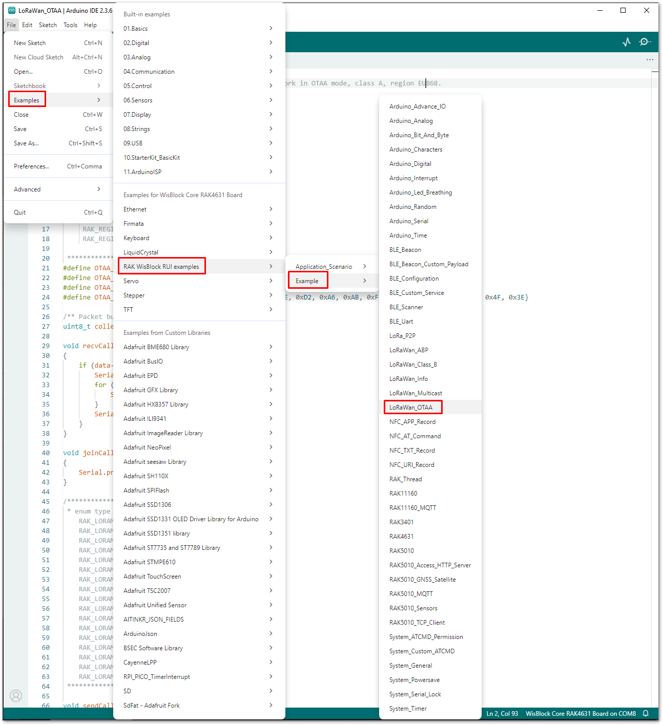 Figure 1: OTAA LoRaWAN application example
- In the example code, modify the device EUI (DEVEUI) and application key (APPKEY).
- The device EUI (DEVEUI) must match the DevEUI registered on your LoRaWAN network server in the previous section. The DEVEUI is MSB.
 // Example OTAA Device EUI MSB
  #define OTAA_DEVEUI   {0xAC, 0x1F, 0x09, 0xFF, 0xFE, 0x06, 0x72, 0x1E}
- Another important parameter to change is the application key (APPKEY). This parameter must match the AppKey configured on your LoRaWAN network server in the previous section. The APPKEY is MSB.
// Example OTAA Application Key MSB
  #define OTAA_APPKEY   {0x21, 0x7D, 0xB8, 0x53, 0x3F, 0xA3, 0x38, 0xC8, 0xBC, 0x49, 0x25, 0xCC, 0xDD, 0x66, 0x43, 0x58}
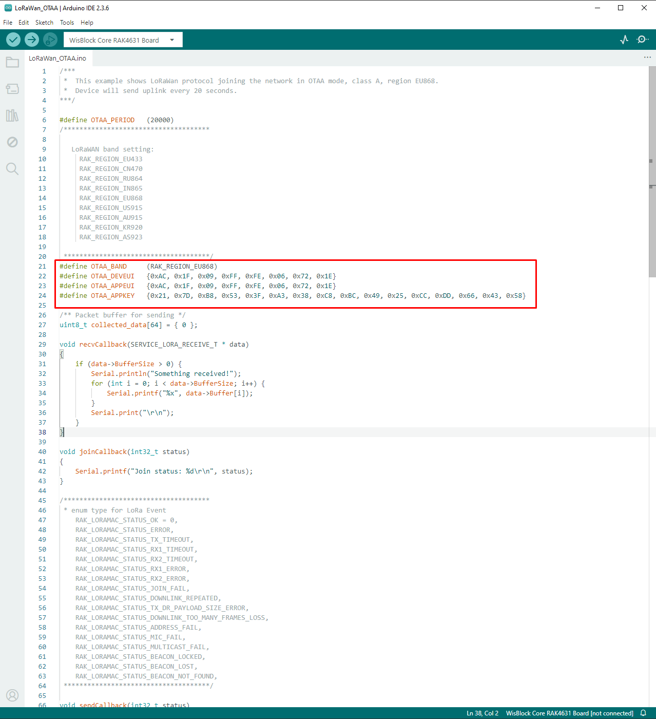 Figure 1: Updating DEVEUI and APPKEY
- This guide uses US915 regional band, so you need to update the band in the code as well. Additionally, set up the channel mask (channels 8 to 15 are the most commonly used channels in the US915 band).
  if(!(ret = api.lorawan.band.set(5)))
  {
       Serial.printf("LoRaWan OTAA - set band is incorrect! \r\n");
       return;
  }

  uint16_t maskBuff = 0x0002;
  api.lorawan.mask.set(&maskBuff);
NOTE
The supported regions are as follows:
- RAK_REGION_EU433 = 0
- RAK_REGION_CN470 = 1
- RAK_REGION_RU864 = 2
- RAK_REGION_IN865 = 3
- RAK_REGION_EU868 = 4
- RAK_REGION_US915 = 5
- RAK_REGION_AU915 = 6
- RAK_REGION_KR920 = 7
- RAK_REGION_AS923-1 = 8
- RAK_REGION_AS923-2 = 9
- RAK_REGION_AS923-3 = 10
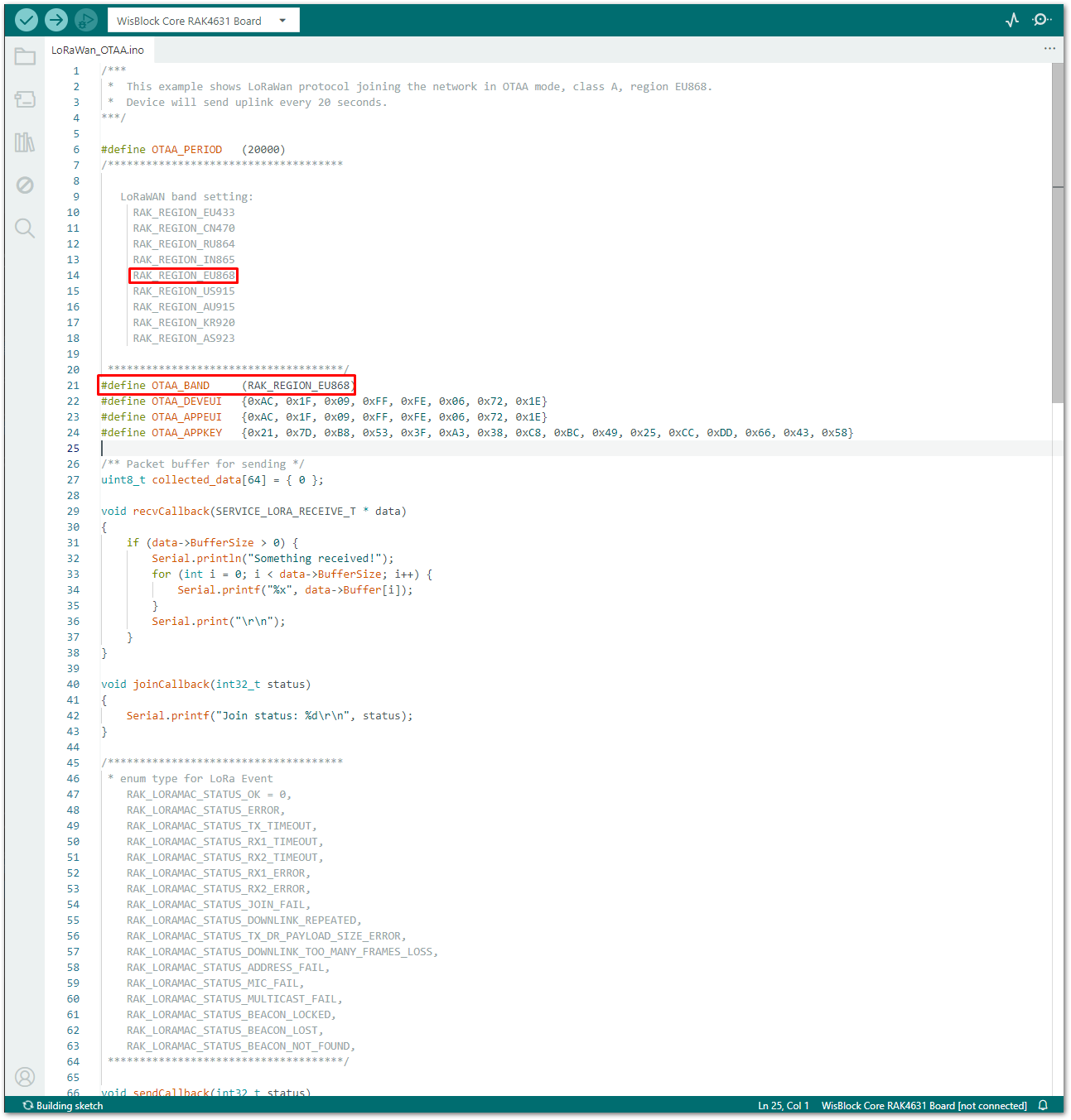 Figure 1: Updating to US915 and setting up channel mask
- The last step is to upload the code by clicking the Upload icon. Take note that you should select the right board and port.
NOTE
The module should automatically go to BOOT mode when the firmware is uploaded via Arduino IDE. If BOOT mode is not initiated, you can manually send AT+BOOT command to start bootloader mode.
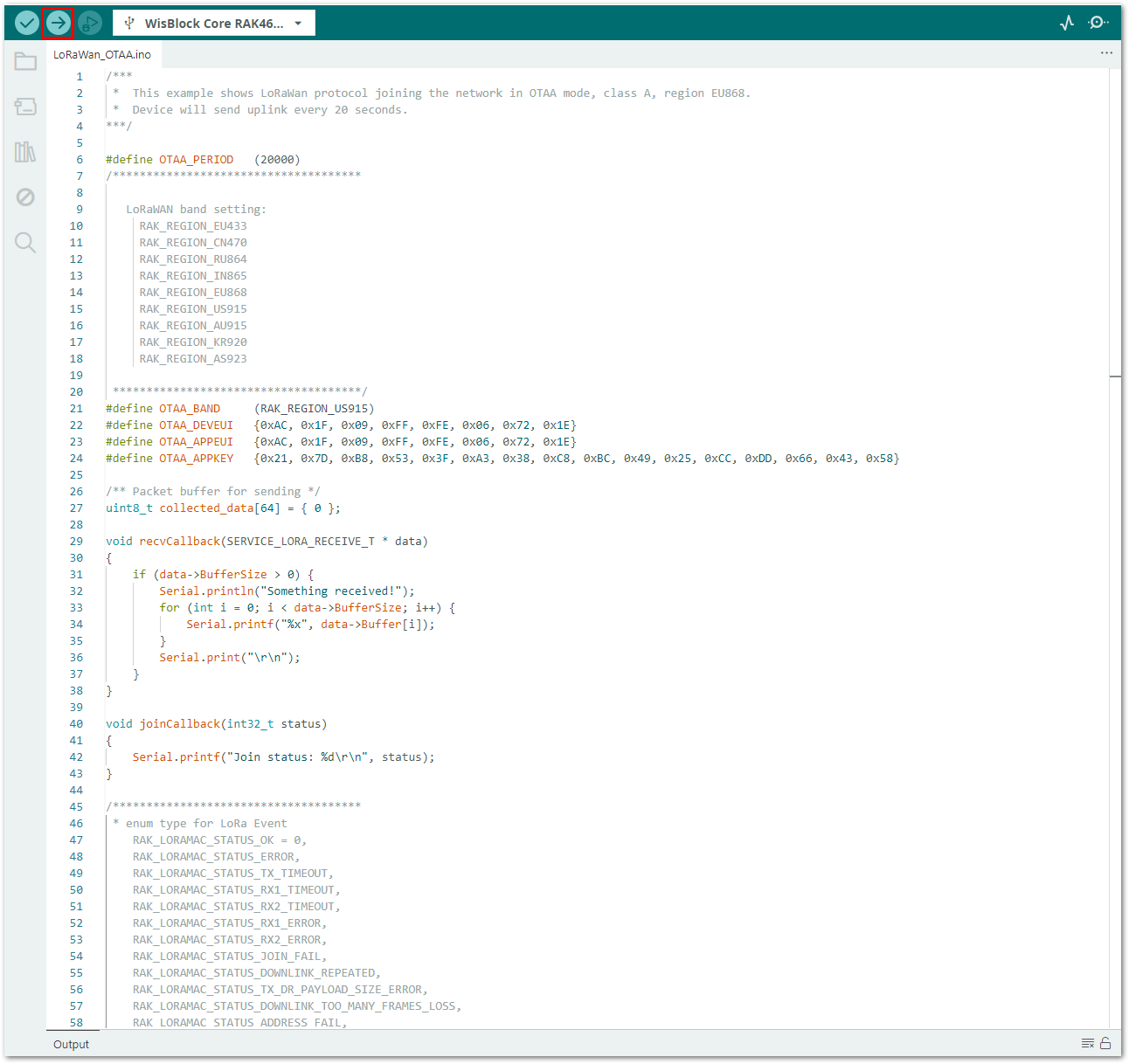 Figure 1: Uploading the code
- You should now be able to view the terminal logs in the Serial Monitor of the Arduino IDE. There are times the COM port may be disconnected, preventing you from viewing of the terminal output immediately. In such cases, you can reconnect the module or try pressing the reset button to see the terminal output.
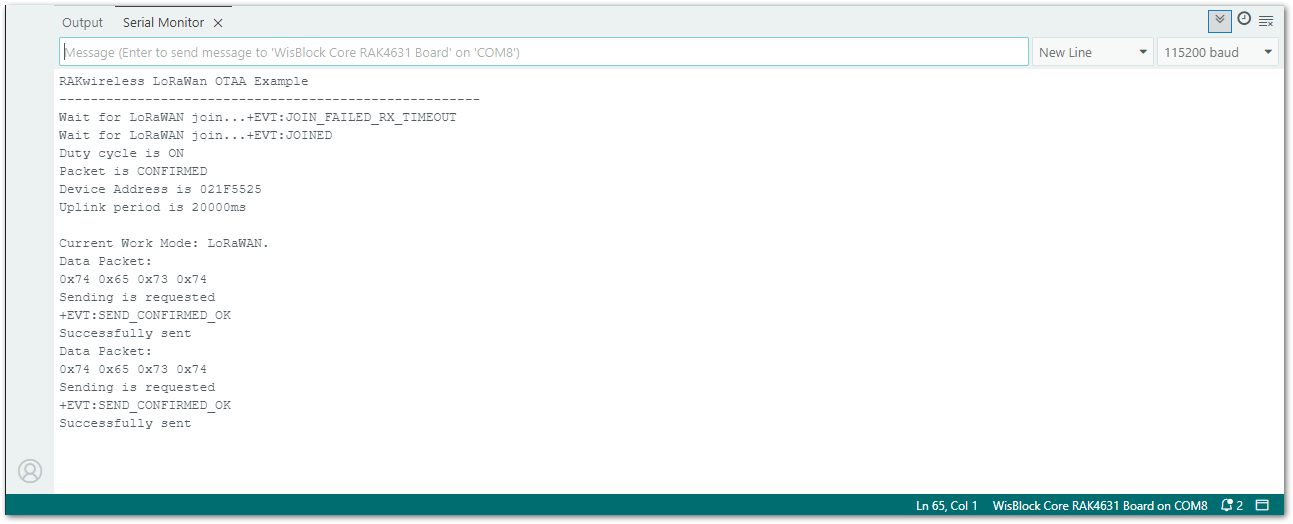 Figure 1: Output logs
- You can also check on the LoRaWAN network server if your device has been successfully joined with the
join requestandjoin acceptlogs.


