index
Supported WisNode Bridge devices can be configured remotely through LoRaWAN® downlink commands. This guide describes the common command format, channel-specific payload definitions, and how to send remote configuration commands through a LoRaWAN Network Server. The available channel types and configurable parameters vary by device. Refer to the documentation for your device to determine which interfaces and channels are supported.
Supported Devices
This remote configuration protocol is supported by the following WisNode Bridge devices. Available channel types depend on the device model and variant.
| Device | DI | DO | Modbus |
|---|---|---|---|
| RAK2461 RS485-DIx4-DOx1 | ✓ | ✓ | ✓ |
| RAK2461 RS485-DOx4 | — | ✓ | ✓ |
| RAK2470 WisNode Bridge Serial Prime | — | — | ✓ |
Prerequisites
Before sending a remote configuration command:
- Ensure that the device is connected to a LoRaWAN Network Server and has successfully joined the network.
- Identify the target Channel ID and the parameter you want to read or modify.
- Use FPort 10 for the remote configuration commands described in this guide.
General Command Format
All remote configuration commands follow this structure:
[Channel ID] [Command Code] [Payload]
| Field | Data Type | Size | Description |
|---|---|---|---|
| Channel ID | u8 | 1 byte | Identifies the channel to be configured. |
| Command Code | u8 | 1 byte | Defines the operation, channel type, channel state, and parameter mode. |
| Payload | Binary array | n bytes | Contains the configuration parameters. The structure depends on the channel type and parameter mode. |
Command Code
The Command Code is an 8-bit field, with Bit 7 as the most significant bit (MSB) and Bit 0 as the least significant bit (LSB).
| Bit Position | Function | Value |
|---|---|---|
| Bit 7 | Get / Set | 0: Get1: Set |
| Bits 6-3 | Channel Type | 0: DI1: DO7: Modbus |
| Bit 2 | Enable / Disable | 0: Disable1: Enable |
| Bits 1-0 | Parameter Mode | 00: Combined01: Individual |
To determine the Command Code, set each bit field according to the required operation, then convert the resulting 8-bit binary value to hexadecimal.
Example 1
For example, to create a Set command for an enabled DI channel in Combined mode:
- Bit 7 =
1→ Set - Bits 6-3 =
0111→ Modbus - Bit 2 =
1→ Enable - Bits 1-0 =
00→ Combined
The resulting binary value is: 1011 1100 which is 0xBC in hexadecimal.
Example 2
For a Combined Get command for a Modbus channel:
- Bit 7 =
0→ Get - Bits 6-3 =
0111→ Modbus - Bit 2 =
0 - Bits 1-0 =
00→ Combined
The resulting binary value is: 0011 1000 which is 0x38 in hexadecimal.
Parameter Modes
Bridge IO supports Combined and Individual parameter modes.
| Operation | Command Structure |
|---|---|
| Combined Get | [Channel ID] [Command Code] |
| Combined Set | [Channel ID] [Command Code] [Payload] |
| Individual Get | [Channel ID] [Command Code] [Parameter Index] |
| Individual Set | [Channel ID] [Command Code] [Parameter Index] [Parameter Value] |
- Combined mode reads or writes all configuration parameters for the selected channel in one command.
- Individual mode reads or writes one parameter identified by its Parameter Index.
Channel Payload Definitions
The payload structure depends on the channel type. Not all channel types are available on every supported device. Refer to Supported Devices before using the following commands.
Digital Input (DI)
Supported on: RAK2461 RS485-DIx4-DOx1
| Parameter | Data Type | Parameter Index |
|---|---|---|
| Debounce | u32 | 0 |
| Interval | u32 | 1 |
Example
Channel ID: 202 (0xCA)
- Debounce:
500 - Interval:
600 - Enable:
True
Combined Get
Read Command:  CA 00
Read Response: CA 04 00 00 01 F4 00 00 02 58
Combined Set
Write Command:  CA 84 00 00 01 F4 00 00 02 58
Write Response: CA 84 00 00 01 F4 00 00 02 58
Individual Set
The following example changes only the Interval to 600 seconds:
Write Command: CA 85 01 00 00 02 58
Digital Output (DO)
Supported on: RAK2461 RS485-DIx4-DOx1 and RS485-DOx4
| Parameter | Data Type | Parameter Index |
|---|---|---|
| Interval | u32 | 0 |
Example
Channel ID: 209 (0xD1)
- Interval:
600 - Enable:
True
Read Command:   D1 08
Read Response:  D1 0C 00 00 02 58
Write Command:  D1 8C 00 00 02 58
Write Response: D1 8C 00 00 02 58
Modbus
The Modbus payload contains the parameters of a Modbus polling task. Combined payload size: 16 bytes
Supported on: RAK2461 and RAK2470
| Parameter | Data Type | Parameter Index |
|---|---|---|
| Device Address | u8 | 0 |
| Function Code | u8 | 1 |
| Register Address | u16 | 2 |
| Quantity | u16 | 3 |
| Data Type | u8 | 4 |
| Scale | f32 | 5 |
| Sensor Type | u8 | 6 |
| Interval | u32 | 7 |
Modbus Data Type Codes
| Data Type | Code | Quantity |
|---|---|---|
| Modbus PDU | 1 | - |
| INT16 BE | 4 | 1 |
| INT16 LE | 5 | 1 |
| UINT16 BE | 6 | 1 |
| UINT16 LE | 7 | 1 |
| INT32 BE (ABCD) | 8 | 2 |
| INT32 LE (DCBA) | 9 | 2 |
| UINT32 BE (ABCD) | 10 | 2 |
| UINT32 LE (DCBA) | 11 | 2 |
| FLOAT BE (ABCD) | 12 | 2 |
| FLOAT LE (DCBA) | 13 | 2 |
| INT32 (CDAB) | 15 | 2 |
| UINT32 (CDAB) | 16 | 2 |
| FLOAT (CDAB) | 17 | 2 |
Scale
The Scale field uses a 32-bit IEEE 754 floating-point value.
| Scale | Hex |
|---|---|
| x1 | 3F800000 |
| x10 | 41200000 |
| x100 | 42C80000 |
| x1000 | 447A0000 |
| x0.1 | 3DCCCCCD |
| x0.01 | 3C23D70A |
| x0.001 | 3A83126F |
Sensor Type Codes
| Sensor Type | Code |
|---|---|
| DigitalInput | 0 |
| DigitalOutput | 1 |
| AnalogInput | 2 |
| AnalogOutput | 3 |
| Nitrogen | 16 |
| Phosphorus | 17 |
| Potassium | 18 |
| Salinity | 19 |
| DissolvedOxygen | 20 |
| ChemicalOxygenDemand | 22 |
| Turbidity | 23 |
| NO3 | 24 |
| NH4 | 25 |
| BOD | 26 |
| Illuminance | 101 |
| Presence | 102 |
| Temperature | 103 |
| AQI | 105 |
| HighPreciseHumidity | 112 |
| Pressure | 115 |
| BatteryLevel | 116 |
| Precipitation | 119 |
| Percentage | 120 |
| CO2Concentration | 125 |
| HighPrecisionEC | 127 |
| VOC | 138 |
| WindSpeed | 146 |
| Strikes | 147 |
| Capacity | 184 |
| Current | 185 |
| Voltage | 186 |
| Moisture | 188 |
| WindDirection | 191 |
| PrecisionEC | 192 |
| PH | 193 |
| PM10 | 227 |
| PM2_5 | 228 |
| Orientation | 229 |
| Noise | 233 |
| RAWDATA_BINARY_MODBUS | 241 |
| RAWDATA_BINARY_2 | 243 |
| RAWDATA_BINARY_4 | 244 |
| GenericFloat32 | 245 |
| GenericInt32 | 246 |
| GenericUint32 | 247 |
| RAWDATA_BINARY | 248 |
Combined Setting Example
Channel ID: 1
- Device Address:
1 - Function Code:
0x03(Read Holding Register) - Register Address:
0 - Quantity:
1 - Data Type:
INT16_BE(4) - Scale:
0.1 - Sensor Type: Temperature (
0x67) - Interval:
60
Read Command:   01 38
Read Response:  01 3C 01 03 00 00 00 01 04 3D CC CC CD 67 00 00 00 3C
Write Command:  01 BC 01 03 00 00 00 01 04 3D CC CC CD 67 00 00 00 3C
Write Response: 01 BC 01 03 00 00 00 01 04 3D CC CC CD 67 00 00 00 3C
The write command is structured as follows:
Individual Setting Example
The following command modifies only Parameter Index 7 (Interval):
01 BD 07 00 00 02 58
01: Channel IDBD: Set + Modbus + Enable + Individual mode07: Parameter Index = Interval00 00 02 58: Interval =600
Send a Configuration Downlink
Before sending a command, ensure that the Bridge IO is online and actively communicating with the LoRaWAN Network Server.
The following sections use a configuration command on FPort 10.
Built-in Network Server
- Log in to the gateway Web UI.
- Go to LoRa > Applications > End devices > Downlink.
- Configure the downlink:
- Frame Confirmation: Enable
- FPort:
10 - HEX Bytes: Enter the hexadecimal command without spaces.
- Click Send.
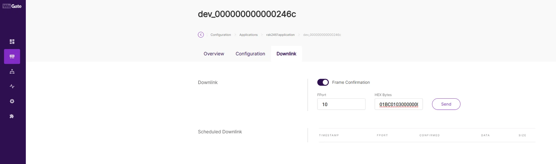 Figure 1: Send a downlink from the Built-in Network Server
The Things Network (TTN)
- Log in to the TTN Console.
- Select the Application and target End Device.
- Go to Messaging > Schedule downlink.
- Configure the downlink:
- Insert Mode:
Replace downlink queue - FPort:
10 - Payload type:
Bytes - Payload: Enter the hexadecimal configuration command.
- Confirmed downlink: Enable
- Insert Mode:
- Click Schedule downlink.
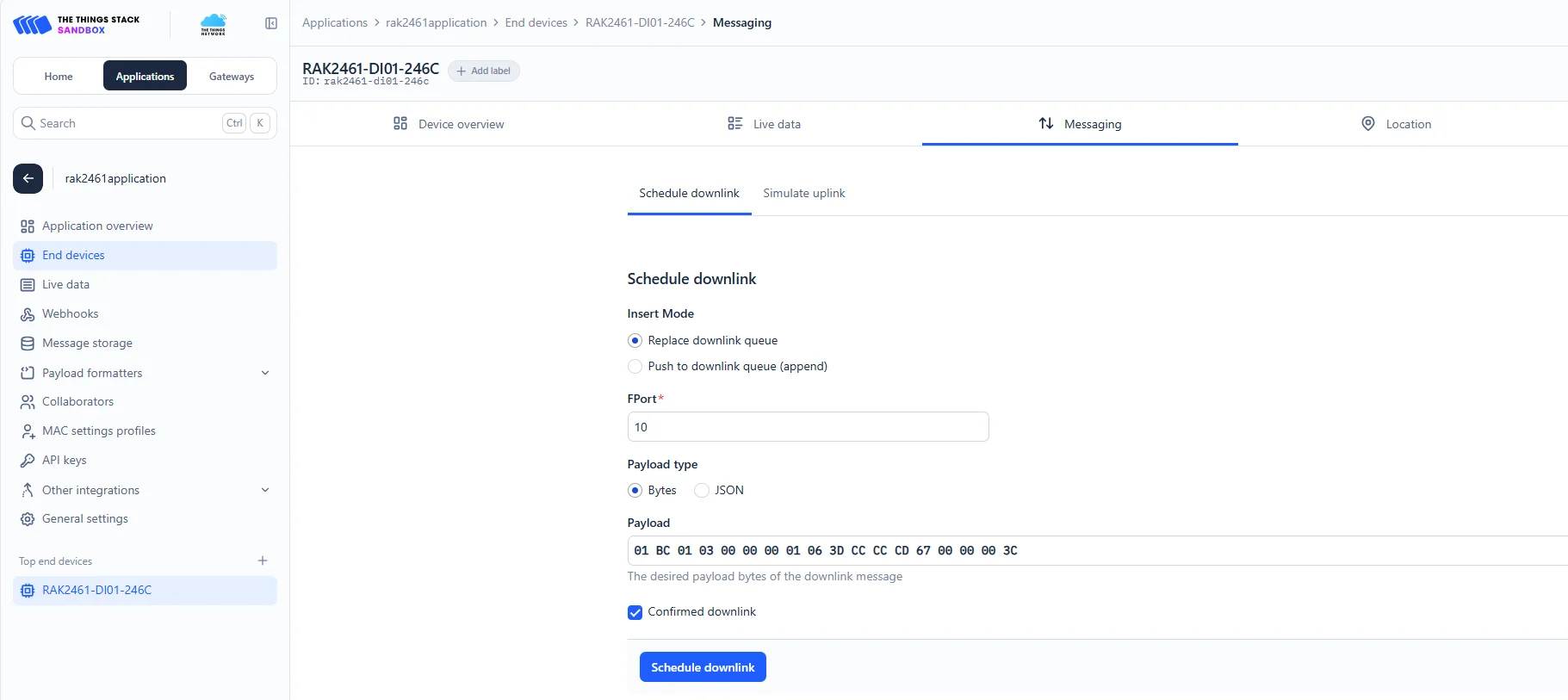 Figure 1: Schedule a downlink in TTN
ChirpStack
- Log in to the ChirpStack Network Server.
- Go to Applications, select the target application, and select the end device.
- Open the Queue tab.
- Configure the downlink:
- Confirmed: Enable
- FPort:
10 - HEX: Enter the hexadecimal configuration command.
- Click Enqueue.
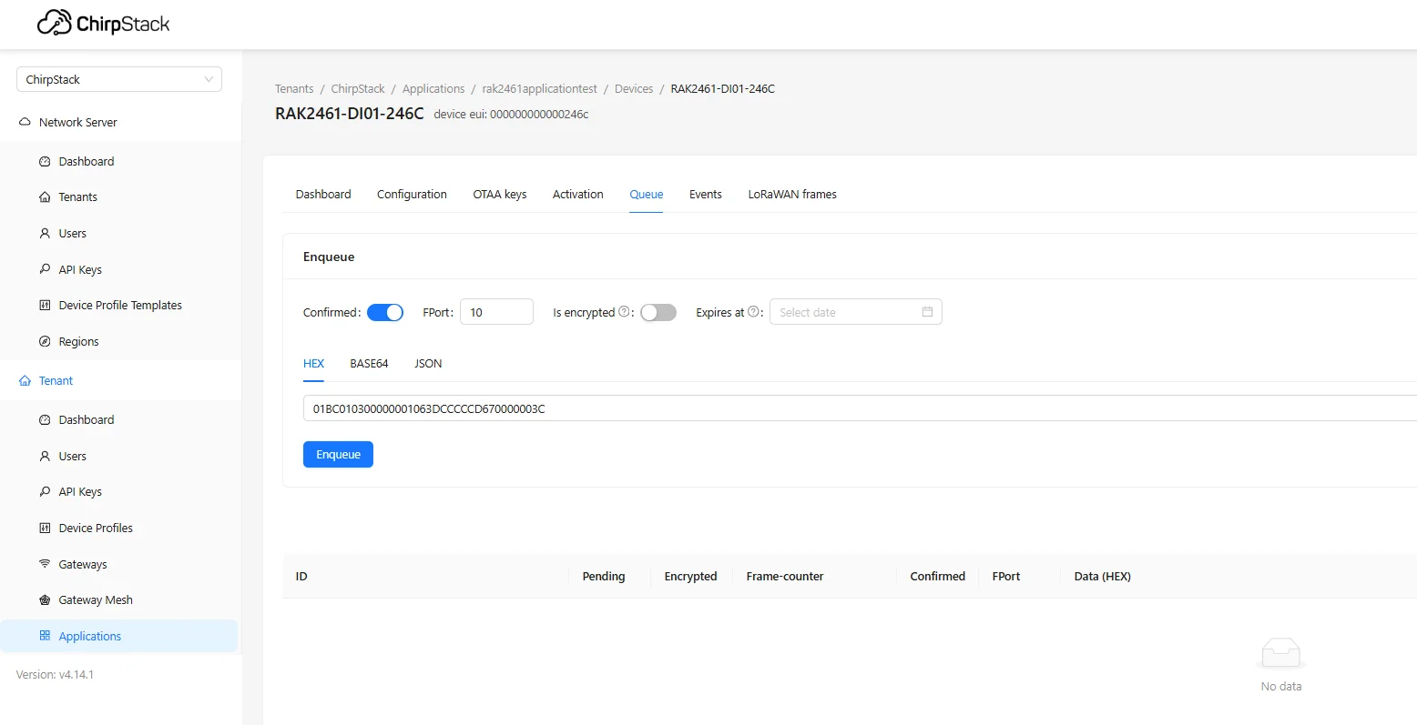 Figure 1: Enqueue a downlink in ChirpStack
Verify the Configuration
After sending a configuration command:
- Check the response returned by the device through the LoRaWAN Network Server.
- If necessary, send a Get command to read the current channel configuration and compare the returned payload with the expected values.
You can also verify the configuration through IO.Box when applicable.


