RAK3112 as a Stand-Alone LoRaWAN End Device
This guide demonstrates how to program RAK3112 as a stand-alone LoRaWAN end-device using Arduino APIs. To communicate over LoRaWAN, the device must be within range of a functioning LoRaWAN gateway connected to a LoRaWAN network server (LNS), either an external server such as The Things Stack (TTN), or a built-in server available on gateways such as WisGate Edge.
Before proceeding, make sure you have completed the hardware setup and Arduino IDE installation described in the RAK3112 Quick Start Guide .
If you are new to LoRaWAN, here are a few good references about LoRaWAN and gateways:
- LoRaWAN 101
- What is a LoRaWAN Gateway
- How do LoRaWAN Gateways work?
- Things to Consider When Picking A LoRaWAN Gateway
RAKwireless LoRaWAN gateway models like WisGate Edge have built-in network servers. It is also common that the LoRaWAN network server is external or in the cloud. The popular LoRaWAN network server in the cloud that you can use for free (but offers enterprise service, too) is TTN .
To run this example correctly, make sure a LoRaWAN gateway is connected to your network server, and create an OTAA application on the network server.
Register the LoRaWAN Gateway on TTN
Choose the appropriate guide below to register and connect your RAK Gateway to The Things Stack (TTN):
- How to Register a RAK Gateway in TTN V3
- How to Connect RAK Gateways to TTN v3 via UDP
- How to Connect RAK Gateways to TTN v3 Using Basics™ Station (LNS)
- How to Auto-Connect RAK Gateway to TTN (EU1) in Packet Forwarder Mode
- How to Connect RAK Gateways to TTN v3 Using Basics™ Station (CUPS)
Register the RAK3112 on TTN
Step 1: Create a TTN Application
-
Log in to The Things Stack using the account and cluster where your gateway is registered.
-
Once logged in, click **Create application **to create a new application.
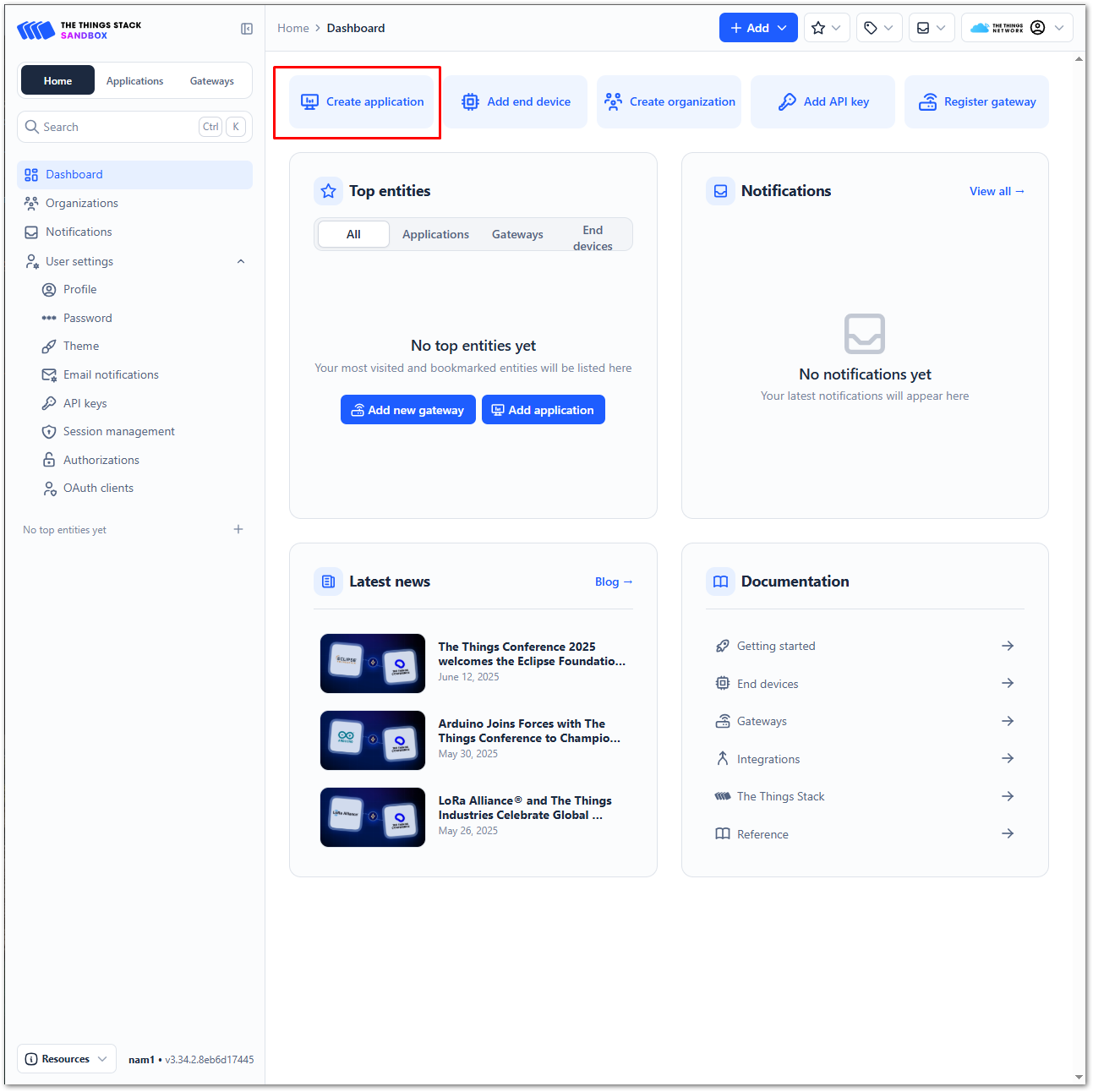 Figure 1: The Things Stack Platform
- To register an application, enter the required details and necessary information about your application, then click Create application.
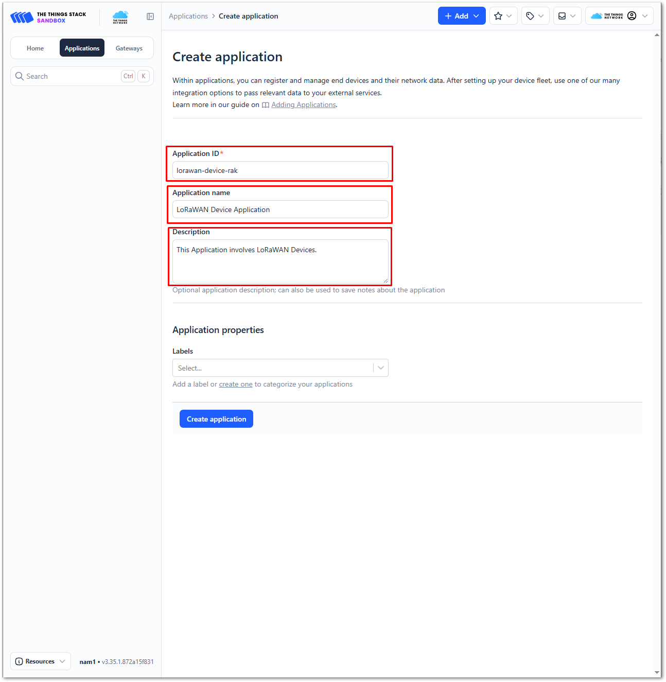 Figure 1: Details of the TTN application
- If you have no error in the previous step, you should now be on the application console page. The next step is to add end-devices to your TTN application.
Step 2: Register an End Device
Each LoRaWAN end device must be registered and activated using either Over-The-Air Activation (OTAA) or Activation By Personalization (ABP). Follow the steps below to register the module on TTN. Some configuration steps and credentials may differ depending on the selected activation method.
- Go to your application console to register a device. To start adding an OTAA end-device, click + Register end device.
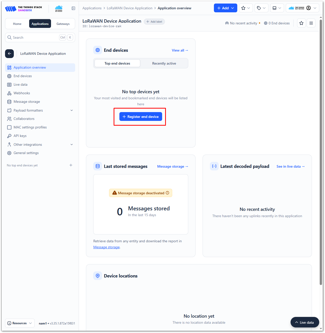 Figure 1: Register end device
- To register the board, select Enter end device specifics manually.
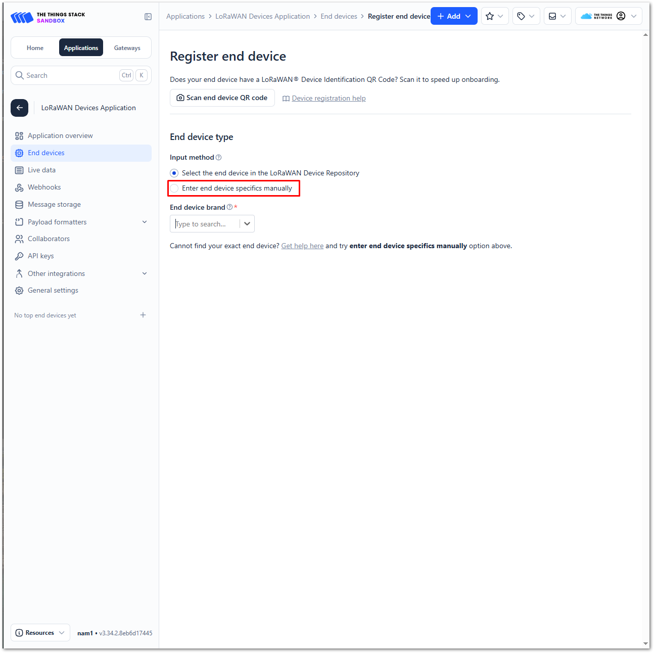 Figure 1: Enter end device specifics manually
- Set up the appropriate Frequency plan, compatible LoRaWAN version, and Regional Parameters version supported by your device. For OTAA activation, set the JoinEUI to all zeros. This step is not required for ABP activation.
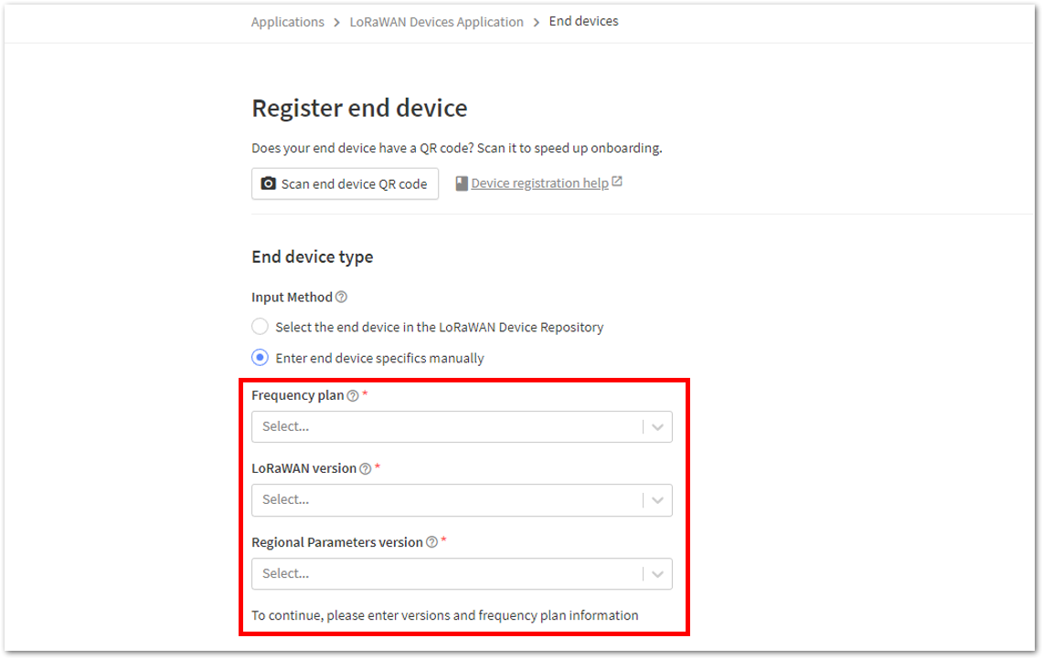 Figure 1: Setting up for your device
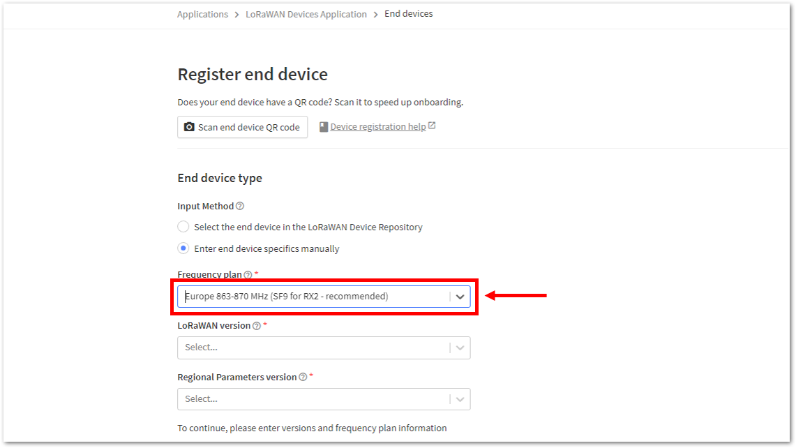 Figure 1: Setting the Frequency plan
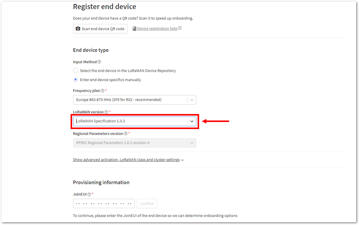 Figure 1: Setting the LoRaWAN version
 Figure 1: Setting the JoinEUI
- Click Show advanced activation, LoRaWAN class and cluster settings. Select the activation method supported by your device and set Additional LoRaWAN class capabilities to Class A only.
- OTAA: Select Over the air activation (OTAA). In the JoinEUI field, enter all zeroes to allow the DevEUI to be configured, then click Confirm.
- ABP: Select Activation by personalization (ABP).
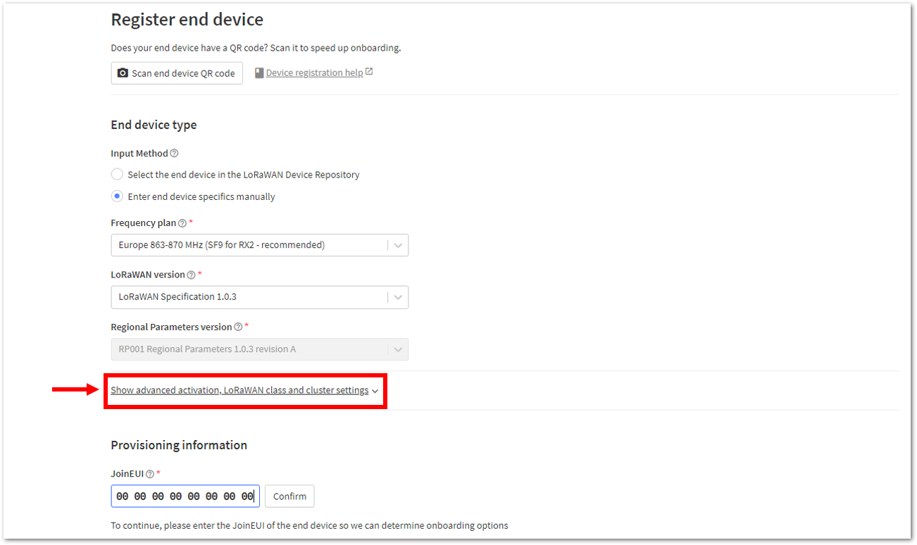 Figure 1: Setting up for your device
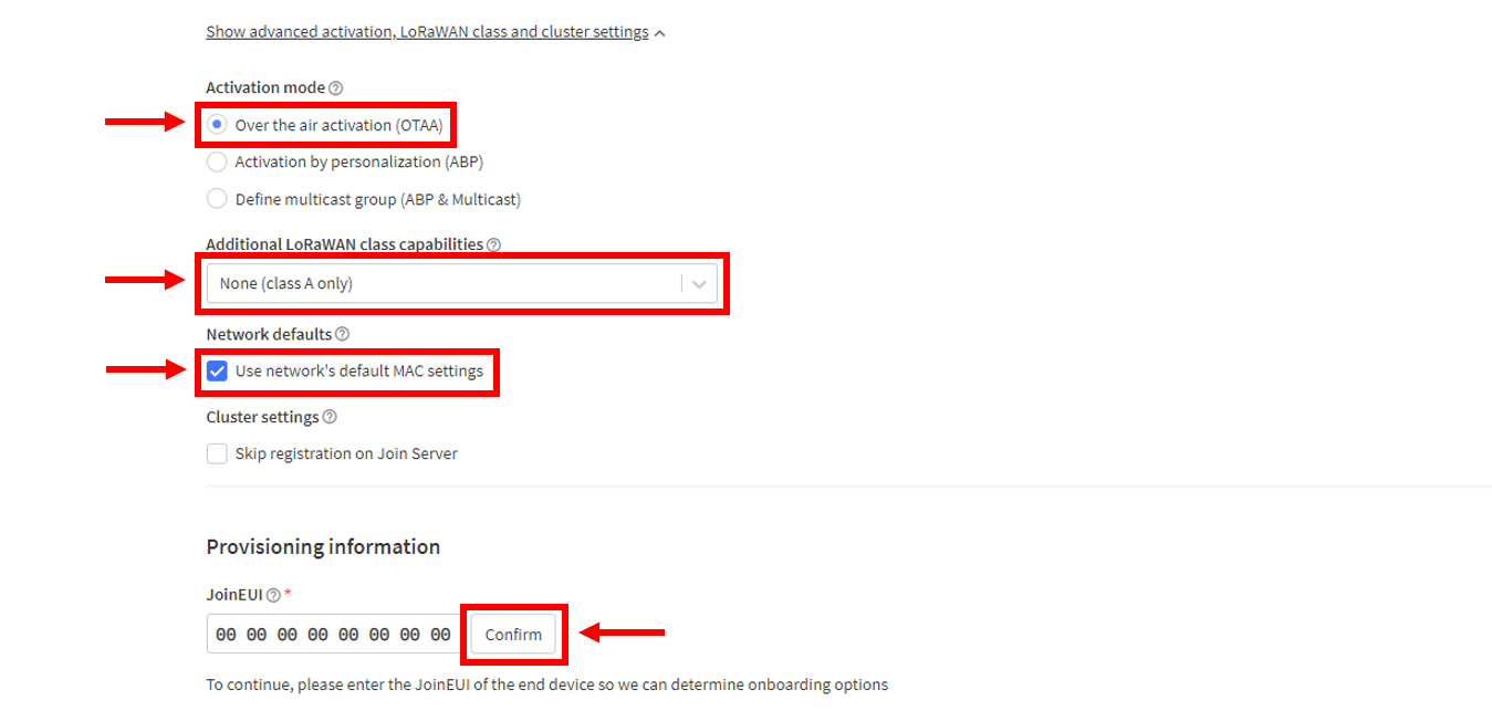 Figure 1: Configuring OTAA activation settings
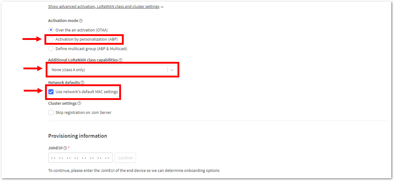 Figure 1: Configuring ABP activation settings
- Enter the DevEUI credentials of your device into the DevEUI portion. This will automatically generate the specific End device ID of your board. Then generate the credentials required by the selected activation method:
- OTAA: Generate the AppKey, then click Register end device.
- ABP: Generate the Device address, AppSKey, and NwkSKey.
- The DevEUI is unique to each RAK device. Depending on the activation mode, the following credentials are hidden in this section and must be generated for your specific device and application:
- ABP: Device address, AppSKey, and NwkSKey.
- OTAA: AppEUI and AppKey.
- For OTAA, the AppEUI is the same as the JoinEUI.
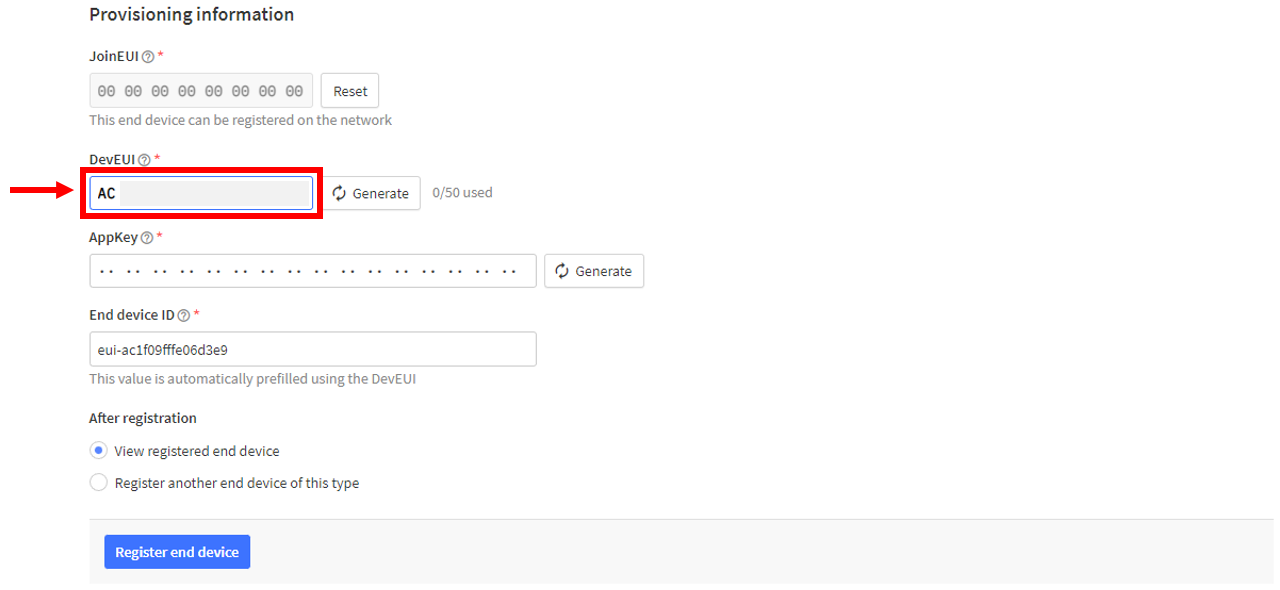 Figure 1: Generating OTAA credentials
 Figure 1: Generating ABP credentials
- Finally, click Register end device.
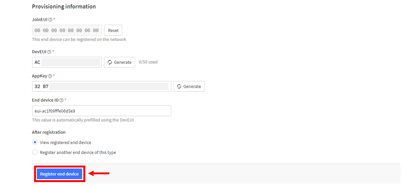 Figure 1: Register end device
- You should now be able to see the device on the TTN console after you fully register your device
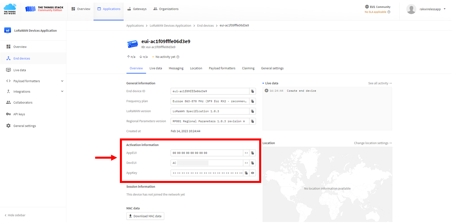 Figure 1: OTAA device successfully registered to TTN
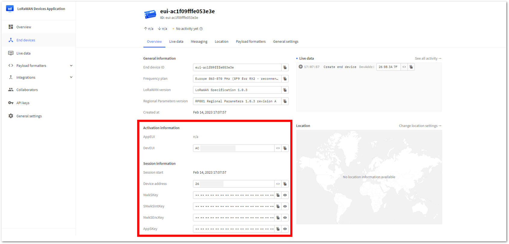 Figure 1: ABP device registered on TTN
Upload the OTAA LoRaWAN Example to RAK3112
After successfully registering the module to the LoRaWAN Network Server as an OTAA device, you can proceed with running the LoRaWAN OTAA demo application example.
- Get the example code from RAK3112_OTAA , and copy the code into the Arduino IDE sketch.
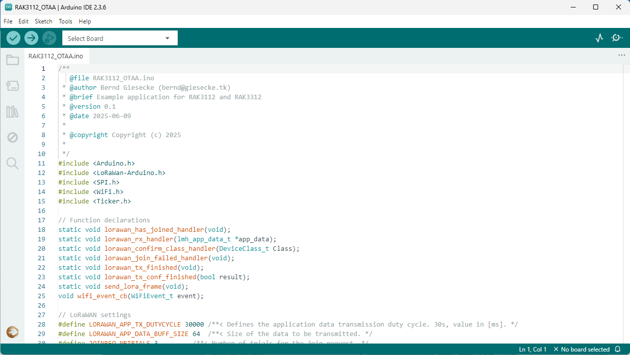 Figure 1: OTAA LoRaWAN application example
- In the example code, modify the device EUI (DEVEUI), application (AppEUI) and application key (AppKey).
- The device EUI (DEVEUI) must match the DevEUI registered on your LoRaWAN network server in the previous section. The DEVEUI is MSB.
// OTAA Device EUI MSB
uint8_t nodeDeviceEUI[8] = {0xac,0x1f,0x09,0xff,0xfe,0x00,0x00,0x00};
- The AppEUI must match the one registered on your LoRaWAN network server as well.
// OTAA Application EUI MSB*
uint8_t nodeAppEUI[8] = {0x70,0xB3,0xD5,0x7E,0xD0,0x02,0x01,0xE1};
- Another important parameter to change is the application key (APPKEY). This parameter must match the AppKey configured on your LoRaWAN network server in the previous section. The APPKEY is MSB.
// Example OTAA Application Key MSB
  #define OTAA_APPKEY   {0x21, 0x7D, 0xB8, 0x53, 0x3F, 0xA3, 0x38, 0xC8, 0xBC, 0x49, 0x25, 0xCC, 0xDD, 0x66, 0x43, 0x58}
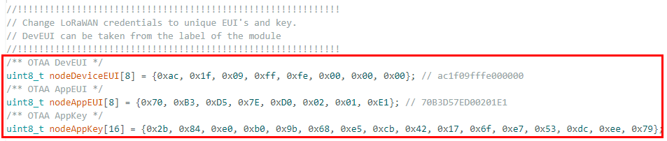 Figure 1: Updating DEVEUI and APPKEY
- This guide uses AS923-3 regional band, so you need to update the band in the code as well.
  if(!(ret = api.lorawan.band.set(5)))
  {
       Serial.printf("LoRaWan OTAA - set band is incorrect! \r\n");
       return;
  }

  uint16_t maskBuff = 0x0002;
  api.lorawan.mask.set(&maskBuff);
RAK3112 supports the regions defined in the SX126x-Arduino library:
- LORAMAC_REGION_EU433 = 4
- LORAMAC_REGION_CN470 = 2
- LORAMAC_REGION_RU864 = 12
- LORAMAC_REGION_IN865 = 7
- LORAMAC_REGION_EU868 = 5
- LORAMAC_REGION_US915 = 8
- LORAMAC_REGION_AU915 = 1
- LORAMAC_REGION_KR920 = 6
- LORAMAC_REGION_AS923 = 0
- LORAMAC_REGION_AS923_2 = 9
- LORAMAC_REGION_AS923_3 = 10
- LORAMAC_REGION_AS923_4 = 11
Additionally, for US915, configuring the channel mask is necessary, with channels 8 to 15 being the most commonly used in this band.
The LoRaWAN region is set in the lmh_init() call:
lmh_init(&lora_callbacks, lora_param_init, true, CLASS_A, LORAMAC_REGION_AS923_3);
- The last step is to upload the code by clicking the Upload icon. Take note that you should select the right board and port.
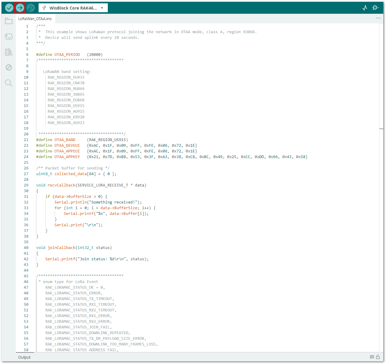 Figure 1: Uploading the code
- You should now be able to view the terminal logs in the Serial Monitor of the Arduino IDE. There are times the COM port may be disconnected, preventing you from viewing of the terminal output immediately. In such cases, you can reconnect the module or try pressing the reset button to see the terminal output.
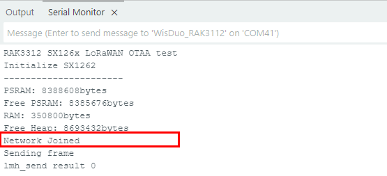 Figure 1: Terminal logs
- Check the Live data section on the LoRaWAN network server to see if the device has successfully joined with the
join requestandjoin acceptlogs.
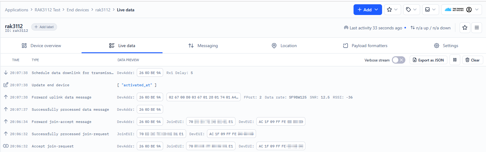 Figure 1: Terminal logs


