RAK3172 WisDuo Module for LoRaWAN®Interface Access Using RUI3
This guide explains how to access the RAK3172 module's GPIO and peripheral interfaces using RUI3 APIs. It includes code examples for digital I/O, analog input, UART, and I2C, along with pinout information for the supported interfaces.
Before using the examples in this guide, make sure you have completed the hardware setup and Arduino IDE installation described in the RAK3172 Quick Start Guide.
Pin assignments and available GPIOs vary by module variant. Refer to the corresponding pinout diagram and pin function table before connecting peripherals or writing code.
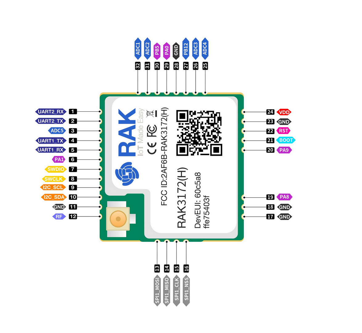 Figure 1: Available Peripherals and Digital I/O pins in RAK3172 module
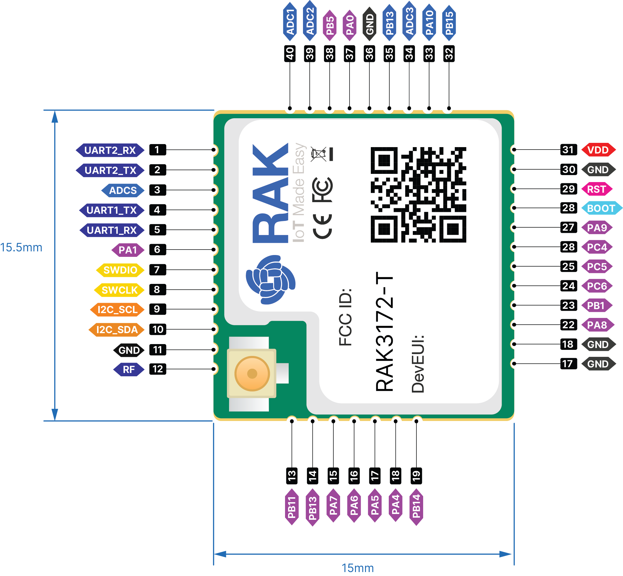 Figure 1: Available Peripherals and Digital I/O pins in RAK3172-F module
Digital I/O Pins
The available pins and their alternative functions vary by module variant. Refer to the corresponding pinout diagram and table below.
RAK3172 and RAK3172-T
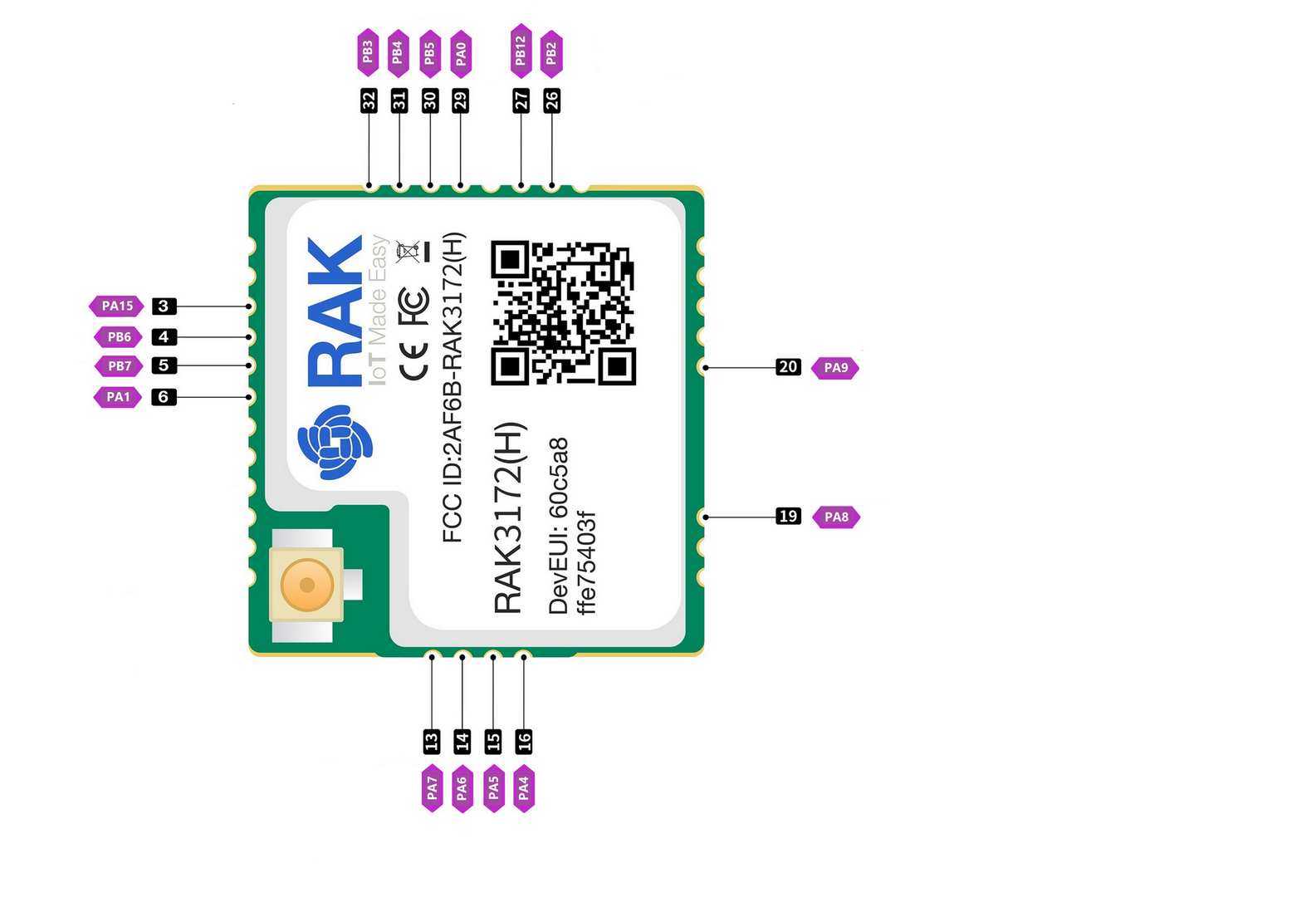 Figure 1: Available Digital I/O pins in RAK3172 module
| Pin Name | Alternative Pin Usage | Pin Name | Alternative Pin Usage |
|---|---|---|---|
| PA0 | - | PA10 | I2C_SDA / ADC4 |
| PA1 | - | PA15 | ADC5 |
| PA4 | SPI1 NSS | PB2 | ADC3 |
| PA5 | SPI1 SCK | PB3 | ADC1 |
| PA6 | SPI1 MISO | PB4 | ADC2 |
| PA7 | SPI1 MOSI | PB5 | - |
| PA8 | - | PB6 | UART1_TX |
| PA9 | I2C_SCL | PB7 | UART1_RX |
RAK3172-F
The RAK3172-F shares a compatible pinout but provides additional GPIOs.
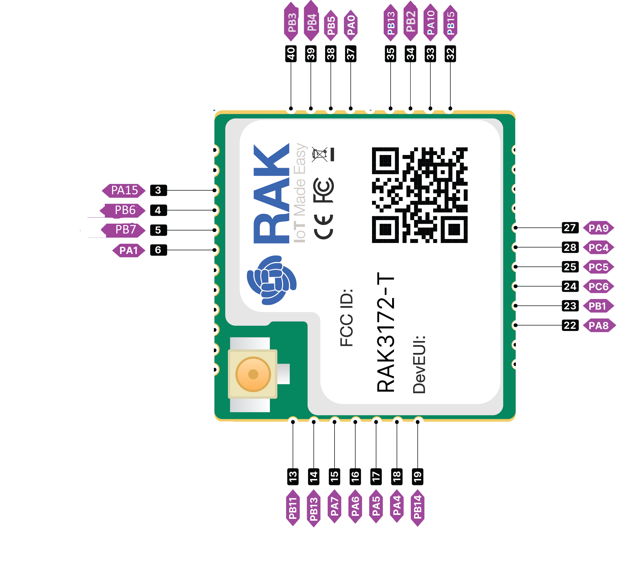 Figure 1: Available Digital I/O pins in RAK3172-F module
| Pin Name | Alternative Pin Usage | Pin Name | Alternative Pin Usage |
|---|---|---|---|
| PA0 | - | PB5 | - |
| PA1 | - | PB6 | UART1_TX |
| PA4 | SPI1 NSS | PB7 | UART1_RX |
| PA5 | SPI1 SCK | PB9 | SPI2 NSS |
| PA6 | SPI1 MISO | PB10 | SPI2 SCK |
| PA7 | SPI1 MOSI | PB11 | - |
| PA8 | - | PB13 | - |
| PA9 | - | PB14 | - |
| PA10 | ADC4 | PB15 | - |
| PA11 | I2C_SCL | PC0 | - |
| PA12 | I2C_SDA | PC1 | SPI2 MOSI |
| PA15 | ADC5 | PC2 | SPI2 MISO |
| PB1 | - | PC3 | - |
| PB2 | ADC3 | PC4 | - |
| PB3 | ADC1 | PC5 | - |
| PB4 | ADC2 | PC6 | - |
The following pins are reserved for dedicated module functions and should not be used as general-purpose GPIOs.
| Pin name | Pin Usage |
|---|---|
| PA2 | UART2_TX |
| PA3 | UART2_RX |
| PA13 | SWDIO |
| PA14 | SWCLK |
| PB8 | RAK3172 Internal |
| PB12 | Internal 10k pull-up resistor for RAK3172 high frequency variant (8xx - 9xx Mhz) or pull-down resistor for RAK3172 low frequency variant (4xx Mhz) |
The RUI3 Arduino API provides the following functions for digital I/O:
-
pinMode(): Configures a GPIO pin as an input or output. -
digitalRead(): Reads the logic level of a digital input pin (HIGHorLOW). -
digitalWrite(): Sets a digital output pin toHIGHorLOW.
Use the GPIO pin name (such as PA0 or PB3) in your code, rather than the physical pin number shown in the pinout diagram.
Click to view the code.
void setup()
{
  pinMode(PA0, OUTPUT); //Change the PA0 to any digital pin you want. Also, you can set this to INPUT or OUTPUT
}

void loop()
{
  digitalWrite(PA0,HIGH); //Change the PA0 to any digital pin you want. Also, you can set this to HIGH or LOW state.
  delay(1000); // delay for 1 second
  digitalWrite(PA0,LOW); //Change the PA0 to any digital pin you want. Also, you can set this to HIGH or LOW state.
  delay(1000); // delay for 1 second
}
Analog Input Pins
The RAK3172 modules provide ADC-capable GPIO pins for reading analog signals. Each pinout diagram identifies the ADC pins available for its corresponding variant.
RAK3172 and RAK3172-T
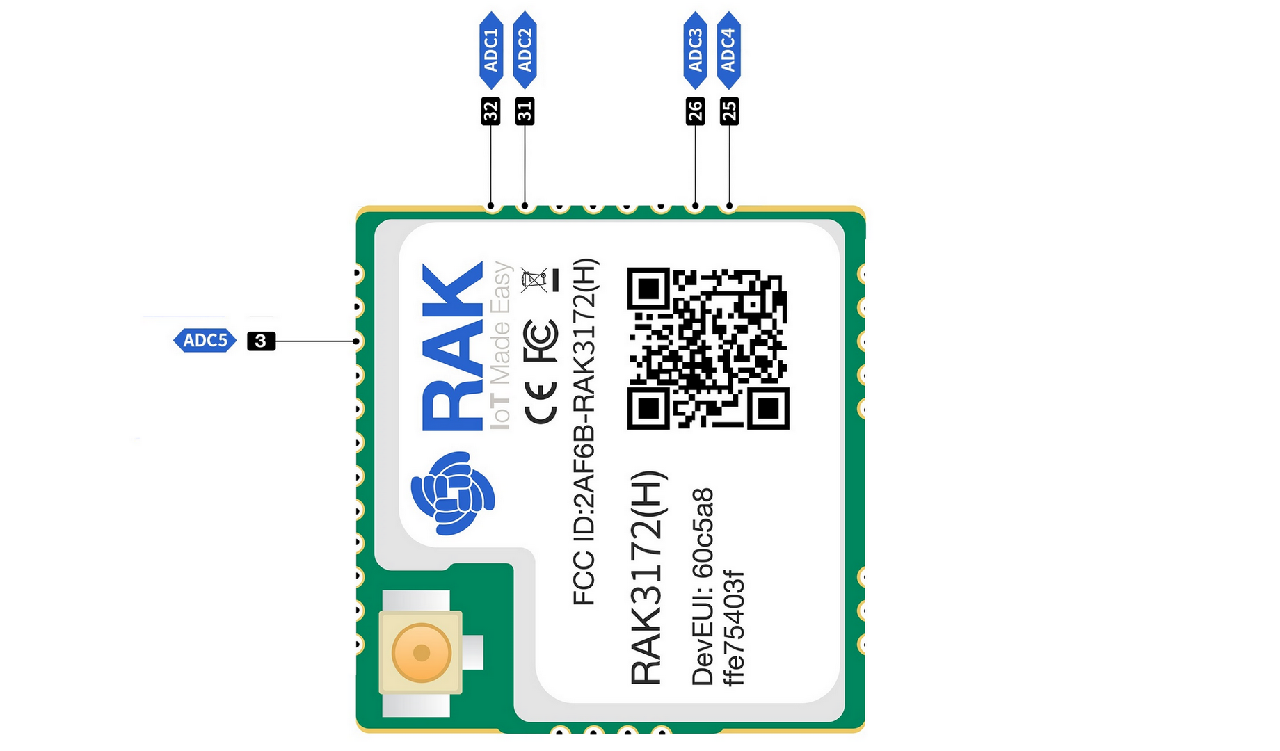 Figure 1: Available Analog pins in RAK3172
RAK3172-F
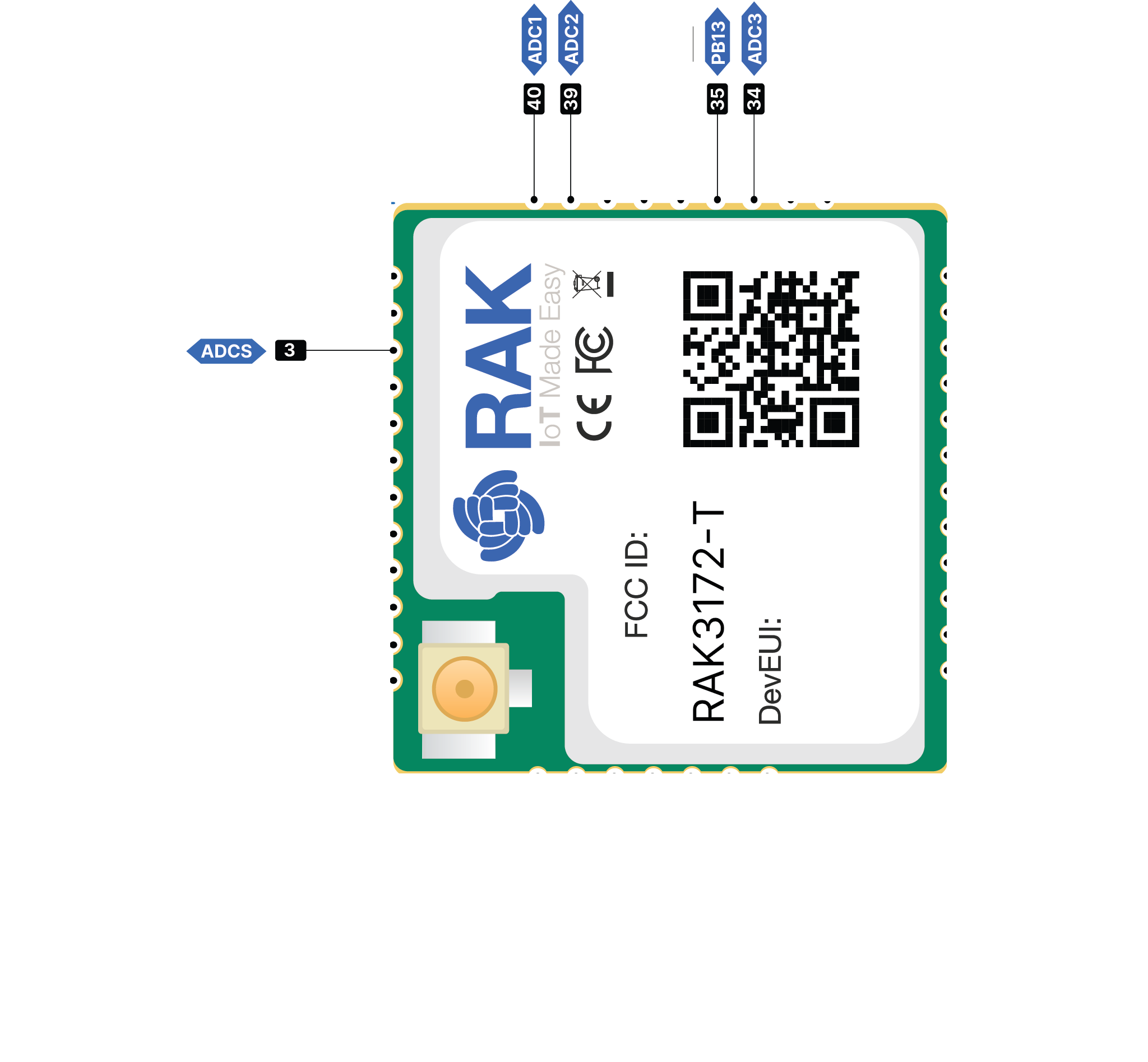 Figure 1: Available Analog pins in RAK3172-F
The following table lists the available ADC channels and their corresponding GPIO pins.
| Analog Port | Pin Name |
|---|---|
| ADC1 | PB3 |
| ADC2 | PB4 |
| ADC3 | PB2 |
| ADC4 | PA10 |
| ADC5 | PA15 |
Use Arduino analogRead to read the value from the specified Analog Input pin.
Click to view the code.
#define analogPin PB3

int val = 0;  // variable to store the value read

void setup()
{
  Serial.begin(115200);
}

void loop()
{
  val = analogRead(analogPin);  // read the input pin
  Serial.println(val);          // debug value
  delay(100);
}
Serial Interfaces
The RAK3172 provides UART, I2C, and SPI interfaces for communication with external devices. The following sections describe their pin assignments and demonstrate how to access these interfaces using RUI3 APIs.
UART
The RAK3172 module provides two UART interfaces, UART1 and UART2. There are also different Serial Operating Modes possible in RUI3, namely Binary Mode, AT Mode, and Custom Mode.
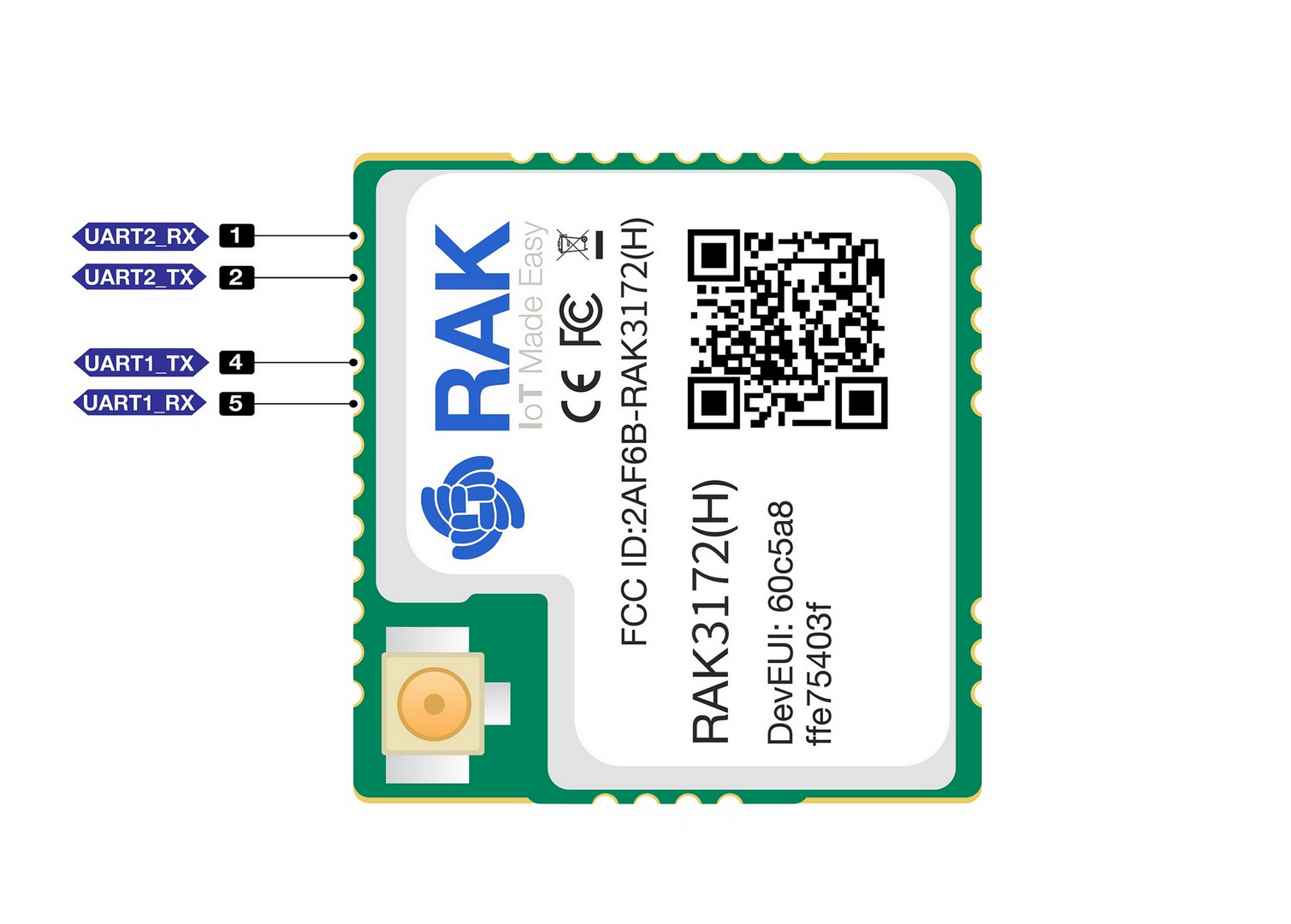 Figure 1: Available UART pins in RAK3172
| Serial Port | Serial Instance Assignment | Default Mode |
|---|---|---|
| UART1 (pins 4, 5) | Serial1 | Custom Mode |
| UART2 (pins 1, 2) | Serial | AT Command |
Click to view the code.
void setup()
{
  Serial1.begin(115200); // use Serial1 for UART1 and Serial for UART2
                         // you can designate separate baudrate for each.
  Serial.begin(115200);
}

void loop()
{
  Serial1.println("RAK3172 UART1 TEST!");
  Serial.println("RAK3172 UART2 TEST!");
  delay(1000); // delay for 1 second
}
I2C
The RAK3172 provides one I2C interface with the following pin assignments:
| I2C Pin Number | I2C Pin Name |
|---|---|
| PA12 | I2C_SCL |
| PA11 | I2C_SDA |
Connect an I2C device to the corresponding SCL and SDA pins before running the I2C scanner example.
Click to view the code.
#include <Wire.h>
void setup()
{
  Wire.begin();

  Serial.begin(115200);
  while (!Serial);
  Serial.println("\nI2C Scanner");
}


void loop()
{
  byte error, address;
  int nDevices;

  Serial.println("Scanning...");

  nDevices = 0;
  for(address = 1; address < 127; address++ )
  {
    // The i2c_scanner uses the return value of
    // the Write.endTransmission to see if
    // a device did acknowledge to the address.
    Wire.beginTransmission(address);
    error = Wire.endTransmission();

    if (error == 0)
    {
      Serial.print("I2C device found at address 0x");
      if (address<16)
        Serial.print("0");
      Serial.print(address,HEX);
      Serial.println("  !");

      nDevices++;
    }
    else if (error==4)
    {
      Serial.print("Unknown error at address 0x");
      if (address<16)
        Serial.print("0");
      Serial.println(address,HEX);
    }

  }
  if (nDevices == 0)
    Serial.println("No I2C devices found\n");
  else
    Serial.println("done\n");

  delay(5000);           // wait 5 seconds for next scan
}
The Arduino Serial Monitor shows the I2C device found.
17:29:15.690 -> Scanning...
17:29:15.738 -> I2C device found at address 0x28  !
17:29:15.831 -> done
17:29:15.831 ->
17:29:20.686 -> Scanning...
17:29:20.733 -> I2C device found at address 0x28  !
17:29:20.814 -> done
17:29:20.814 ->
SPI
The RAK3172 provides an SPI1 interface through the PA4 to PA7 pins. When using SPI1 in your RUI3 project, these pins are assigned to the SPI interface and should not be used for other GPIO functions.
PA13 and PA14 pins are reserved for SWD debug interface. Check the Connect to the RAK3172 section.


