RAK3272S Breakout Board Interface Access Using RUI3
This guide shows how to use RUI3 APIs to access the peripherals of RAK3272S Breakout Board. It includes code examples for digital I/O, UART, and I2C, as well as pinout information for SPI.
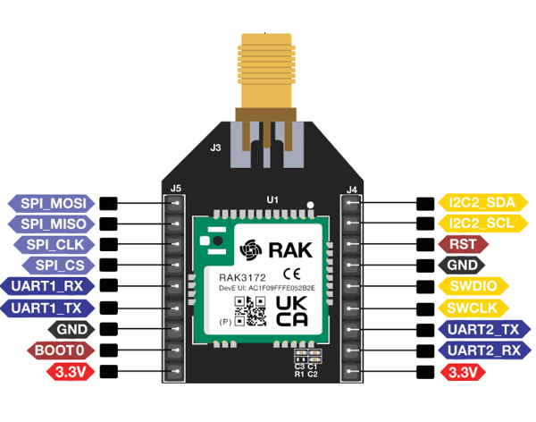 Figure 1: Available Peripheral pins in RAK3272S Breakout Board
Before using the examples in this guide, make sure you have completed the hardware setup and Arduino IDE installation described in the RAK3272 Breakout Board Quick Start Guide.
Digital I/O Pins
Here‘s the available digital I/O pins in RAK3272S board.
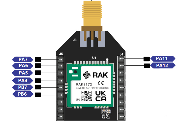 Figure 1: Available Digital I/O pins in RAK3272S
| Pin Name | J Connector pin |
|---|---|
| PA4 | J5 pin 4 |
| PA5 | J5 pin 3 |
| PA6 | J5 pin 2 |
| PA7 | J5 pin 1 |
| PA8 | J4 pin 1 |
| PA9 | J4 pin 2 |
| PB6 | J5 pin 5 |
| PB7 | J5 pin 6 |
The RUI3 Arduino API provides the following functions for digital I/O:
-
pinMode(): Configures a GPIO pin as an input or output. -
digitalRead(): Reads the logic level of a digital input pin (HIGHorLOW). -
digitalWrite(): Sets a digital output pin toHIGHorLOW.
The GPIO Pin Name is the one to be used on the digitalRead and digitalWrite and NOT the pin numbers.
Click to view the code.
void setup()
{
  pinMode(PA7, OUTPUT); //Change the P0_04 to any digital pin you want. Also, you can set this to INPUT or OUTPUT
}

void loop()
{
  digitalWrite(PA7,HIGH); //Change the PA0 to any digital pin you want. Also, you can set this to HIGH or LOW state.
  delay(1000); // delay for 1 second
  digitalWrite(PA7,LOW); //Change the PA0 to any digital pin you want. Also, you can set this to HIGH or LOW state.
  delay(1000); // delay for 1 second
}
Serial Interfaces
The RAK3272S Breakout Board provides UART, I2C, and SPI interfaces for communication with external devices. The following sections describe their pin assignments and demonstrate how to access these interfaces using RUI3 APIs.
UART
There are two UART peripherals available on the RAK3272S. There are also different Serial Operating Modes possible in RUI3, namely Binary Mode, AT Mode, and Custom Mode.
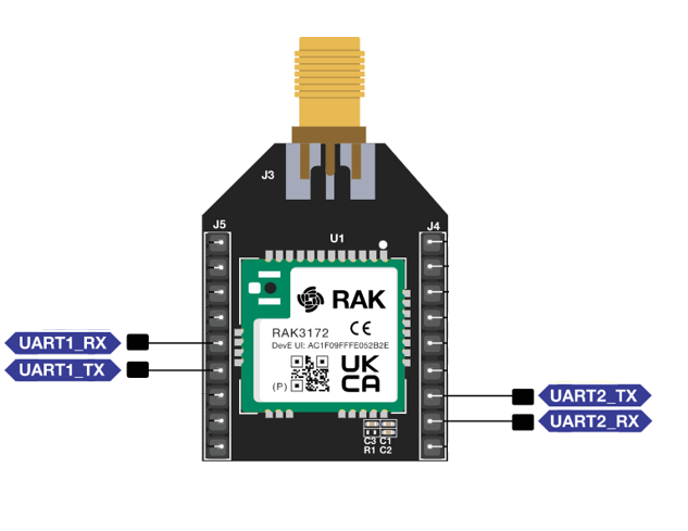 Figure 1: Available UART pins in RAK3272S
| Serial Port | UART pin number | Serial Instance Assignment | Default Mode |
|---|---|---|---|
| UART1_TX | J5 pin 6 | Serial1 | Custom Mode |
| UART1_RX | J5 pin 5 | Serial1 | Custom Mode |
| UART2_TX | J4 pin 7 | Serial | AT Command |
| UART2_RX | J4 pin 8 | Serial | AT Command |
Click to view the code.
void setup()
{
  Serial1.begin(115200); // use Serial1 for UART1 and Serial for UART2
                         // you can designate separate baudrate for each.
  Serial.begin(115200);
}

void loop()
{
  Serial1.println("RAK3172 UART1 TEST!");
  Serial.println("RAK3172 UART2 TEST!");
  delay(1000); // delay for 1 second
}
I2C
There is one I2C peripheral available on RAK3272S. Make sure you have an I2C device connected to specified I2C pins to run the I2C scanner code.
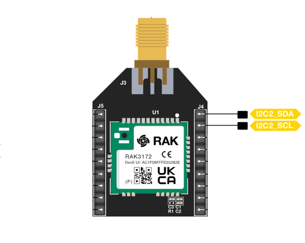 Figure 1: Available I2C pins in RAK3272S
| I2C Pin Number | I2C Pin Name |
|---|---|
| J4 pin 1 | I2C2_SDA |
| J4 pin 2 | I2C2_SCL |
Use Arduino Wire library to communicate with I2C devices.
Click to view the code.
#include <Wire.h>

void setup()
{
  Wire.begin();

  Serial.begin(115200);
  while (!Serial);
  Serial.println("\nI2C Scanner");
}


void loop()
{
  byte error, address;
  int nDevices;

  Serial.println("Scanning...");

  nDevices = 0;
  for(address = 1; address < 127; address++ )
  {
    // The i2c_scanner uses the return value of
    // the Write.endTransmission to see if
    // a device did acknowledge to the address.
    Wire.beginTransmission(address);
    error = Wire.endTransmission();

    if (error == 0)
    {
      Serial.print("I2C device found at address 0x");
      if (address<16)
        Serial.print("0");
      Serial.print(address,HEX);
      Serial.println("  !");

      nDevices++;
    }
    else if (error==4)
    {
      Serial.print("Unknown error at address 0x");
      if (address<16)
        Serial.print("0");
      Serial.println(address,HEX);
    }
  }
  if (nDevices == 0)
    Serial.println("No I2C devices found\n");
  else
    Serial.println("done\n");

  delay(5000);           // wait 5 seconds for next scan
}
The Arduino Serial Monitor shows the I2C device found.
17:29:15.690 -> Scanning...
17:29:15.738 -> I2C device found at address 0x28  !
17:29:15.831 -> done
17:29:15.831 ->
17:29:20.686 -> Scanning...
17:29:20.733 -> I2C device found at address 0x28  !
17:29:20.814 -> done
17:29:20.814 ->
SPI
If your RUI3 project uses SPI, then J5 pins 1 to 4 are reserved for RUI3 SPI interface.
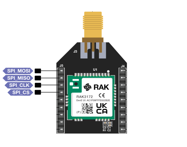 Figure 1: Available SPI pins in RAK3272S
| SPI Pin Number | SPI Pin Name |
|---|---|
| J5 pin 1 | SPI_MOSI |
| J5 pin 2 | SPI_MISO |
| J5 pin 3 | SPI_CLK |
| J5 pin 4 | SPI_CS |
The J4 pins 5 and 6 are reserved for the SWD debug interface. Refer to the RAK3272S Breakout Board Quick Start Guide. section for more details.


