RAK4630 WisDuo LoRaWAN + BLE Module Interface Access with RUI3
This guide shows how to use RUI3 APIs to access the pinouts of RAK4630. It includes code examples for digital I/O, analog input, UART, and I2C, as well as pinout information for SPI.
Before using the examples in this guide, make sure you have completed the hardware setup and Arduino IDE installation described in the RAK4630 Quick Start Guide.
Digital I/O Pins
You can use any of the pins shown in this section, as Digital Pin by replacing the dot . to underscore _.
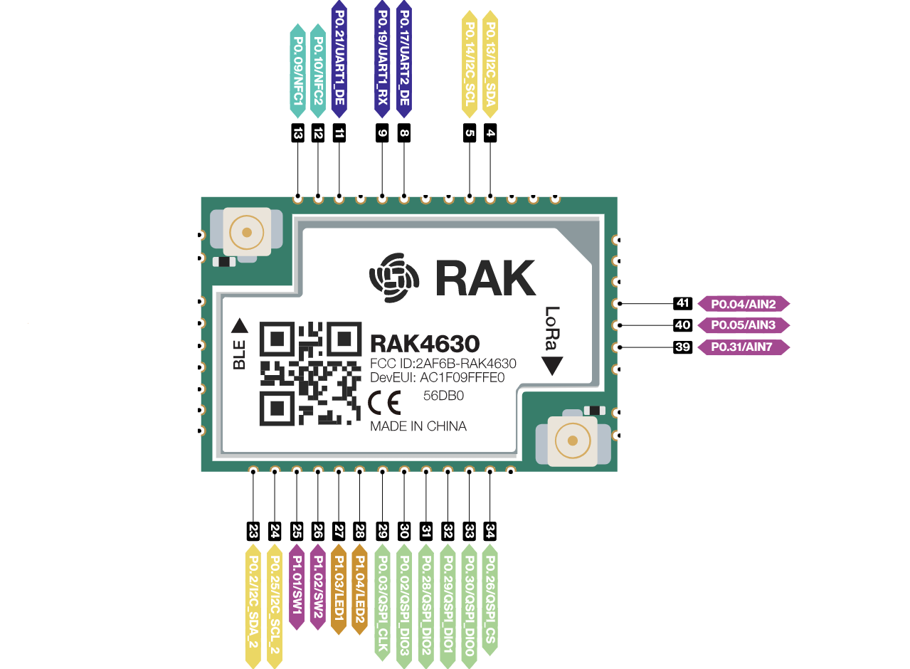 Figure 1: Available digital I/O pins in RAK4630
Click to view the code.
/*
 RAK4631 Digital I/O Example

 You can use any of the following as Digital I/O:

 P0_03
 P0_04
 P0_05
 P0_09
 P0_10
 P0_13
 P0_14
 P0_17
 P0_19
 P0_21
 P0_24
 P0_25
 P0_26
 P0_28
 P0_29
 P0_30
 P0_31
 P1_01
 P1_02
 P1_03
 P1_04
*/

void setup()
{
  pinMode(P0_04, OUTPUT); //Change the P0_04 to any digital pin you want. Also, you can set this to INPUT or OUTPUT
}

void loop()
{
  digitalWrite(P0_04,HIGH); //Change the P0_04 to any digital pin you want. Also, you can set this to HIGH or LOW state.
  delay(1000); // delay for 1 second
  digitalWrite(P0_04,LOW); //Change the P0_04 to any digital pin you want. Also, you can set this to HIGH or LOW state.
  delay(1000); // delay for 1 second
}
Analog Input Pins
You can use any of the pins shown in this section, as Analog Input Pin by replacing the dot . to underscore _.
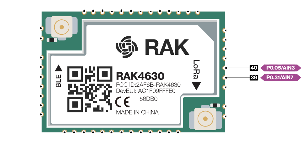 Figure 1: Available analog input pins in RAK4630
Click to view the code.
#define analogPin P0_05  // or you can use P0_31

int val = 0;  // variable to store the value read

void setup()
{
  Serial.begin(115200);
}

void loop()
{
  val = analogRead(analogPin);  // read the input pin
  Serial.println(val);          // debug value
}
Serial Interfaces
The RAK4630 provides two UART peripherals, as well as I2C and SPI interfaces for communication with external devices.
UART
There are two UART peripherals available on RAK4630. There are also different Serial Operating Modes possible in RUI3, namely Binary Mode, AT Mode, and Custom Mode.
| Serial Port | Serial Instance Assignment | Default Mode |
|---|---|---|
| UART1 (pin 19, 20) | Serial0 | AT Command |
| UART2 (pin 15, 16) | Serial1 | Custom Mode |
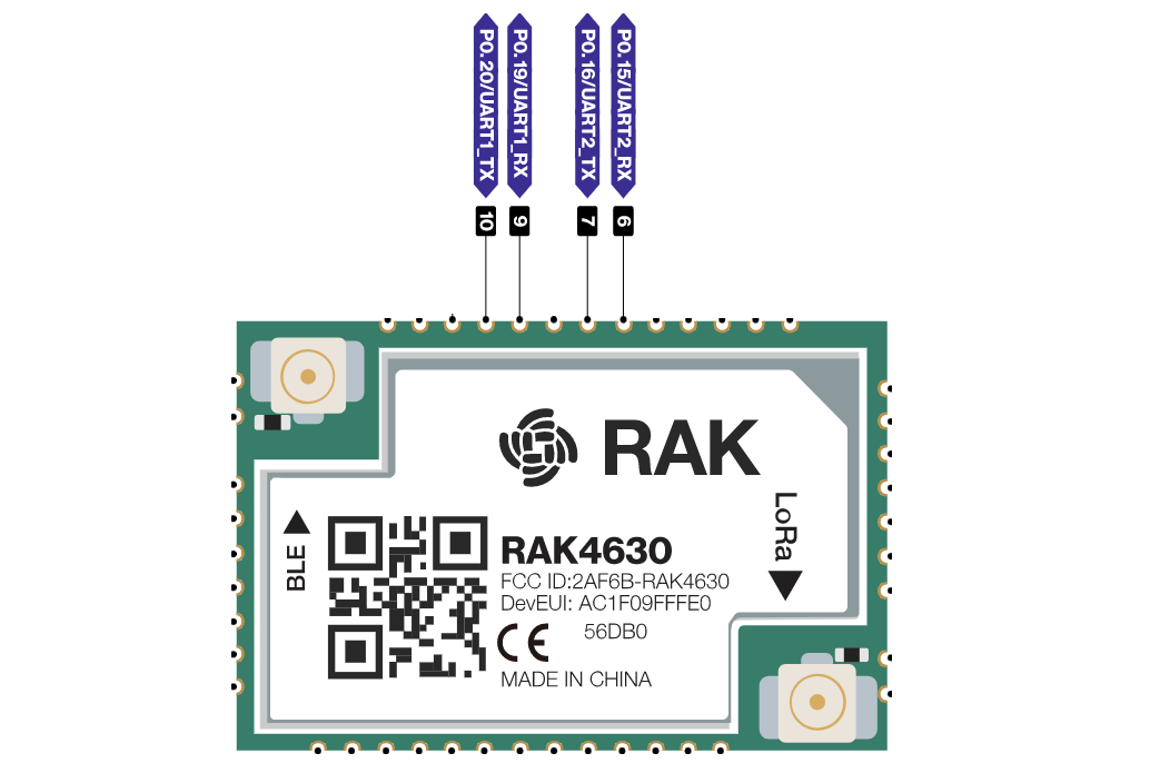 Figure 1: Available UART pins in RAK4630
Click to view the code.
void setup()
{
  Serial0.begin(115200);
}

void loop()
{
  Serial0.println("RAK4630 TEST!");
  delay(1000);
}
For additional serial configuration options, see RUI3 Serial Operating Modes.
I2C
Connect an I2C device to the corresponding pins before running the example.
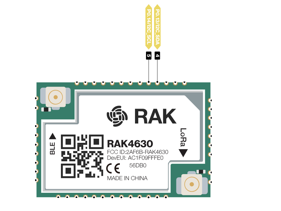 Figure 1: Available I2C pins in RAK4630
Click to view the code.
#include <Wire.h>

void setup()
{
  Wire.begin();

  Serial.begin(115200);
  while (!Serial);
  Serial.println("\nI2C Scanner");
}

void loop()
{
  byte error, address;
  int nDevices;

  Serial.println("Scanning...");

  nDevices = 0;
  for(address = 1; address < 127; address++ )
  {
    // The i2c_scanner uses the return value of
    // the Write.endTransmisstion to see if
    // a device did acknowledge to the address.
    Wire.beginTransmission(address);
    error = Wire.endTransmission();

    if (error == 0)
    {
      Serial.print("I2C device found at address 0x");
      if (address<16)
        Serial.print("0");
      Serial.print(address,HEX);
      Serial.println("  !");

      nDevices++;
    }
    else if (error==4)
    {
      Serial.print("Unknown error at address 0x");
      if (address<16)
        Serial.print("0");
      Serial.println(address,HEX);
    }
  }
  if (nDevices == 0)
    Serial.println("No I2C devices found\n");
  else
    Serial.println("done\n");

  delay(5000);           // wait 5 seconds for next scan
}
SPI
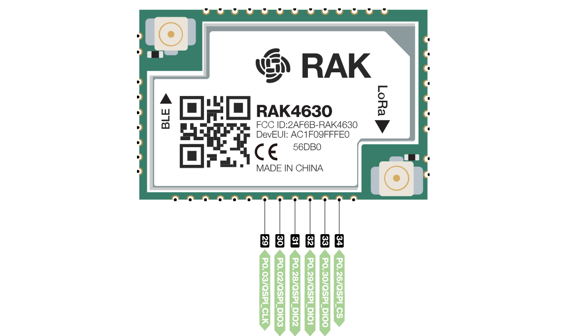 Figure 1: Available SPI pins in RAK4630
Refer to the pinout diagram to identify the SPI pins for your hardware design.


