RAK4630 WisDuo Module as a Stand-Alone LoRaWAN End Device
This guide demonstrates how to program RAK4630 as a stand-alone LoRaWAN end-device using RUI3 Arduino APIs. To utilize RAK4630 as a LoRaWAN end-device, it must be in proximity to a functioning LoRaWAN gateway registered to a LoRaWAN network server (LNS) or with a built-in network server.
The example uses the built-in LoRaWAN network server on the WisGate Edge RAK7268 LoRaWAN gateway. RAK provides a range of WisGate LoRaWAN gateways available for purchase from the RAK store . This guide concentrates on configuring RAK4630 as a LoRaWAN end-device.
Before proceeding, make sure you have completed the hardware setup and Arduino IDE installation described in the RAK4630 Quick Start Guide.
If you are new to LoRaWAN, here are a few good references about LoRaWAN and gateways:
- LoRaWAN 101
- What is a LoRaWAN Gateway
- How do LoRaWAN Gateways work?
- Things to Consider When Picking A LoRaWAN Gateway
LoRaWAN gateway models like WisGate Edge often come with built-in network servers. However, it's also common for LoRaWAN network servers to be external or in the cloud. One popular LoRaWAN network server in the cloud, which offers free usage with enterprise services available, is The Things Network (TTN).
Register RAK4630 on the LoRaWAN Network Server
This initial guide utilizes the LoRaWAN built-in network server of RAK7268V2, but you have the flexibility to use another LoRaWAN network server such as TTN, ChirpStack, Helium, AWS, etc. While these platforms may have different user interfaces, the parameters to be configured should remain the same as long as they adhere to the LoRaWAN specification standard.
- You need to have a functional RAK7268V2 to proceed with the next steps. For a complete guide, refer to RAK7268V2 WisGate Edge Quick Start Guide. Other WisGate Edge configurations can be found in the detailed documentation of the WisGate OS.
This section will guide you through adding a LoRaWAN application to the built-in network server of RAK7268V2 and adding a device to it. To perform these configurations, you'll need access to the RAK7268V2 console portal. The IP address you use to access the portal will depend on your type of connection to RAK7268V2. For instance, if your RAK7268V2 is configured as an Access Point, you can connect to it via http://192.168.230.1/.
- Once you have a functioning RAK7268V2 gateway, ensure that you are using the built-in LoRaWAN network server (LNS). You can configure this by selecting the Configuration button on the left sidebar.
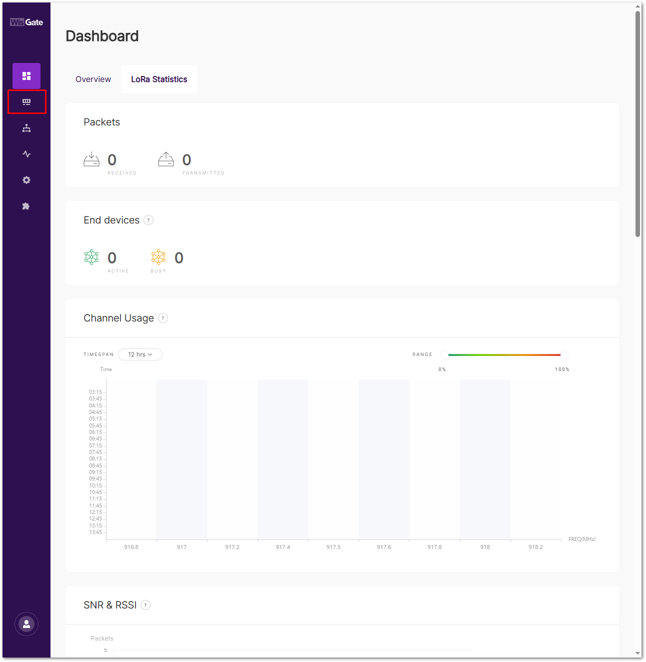 Figure 1: RAK7268V2 LoRa network settings
- On the Work mode elect Built-in network server and make sure to take note of the Region setting. The Region should match the region specified in the code for the WisNode Module that you will compile later in this guide. For instance, the region of the LoRaWAN gateway and LNS used in this guide is US915.
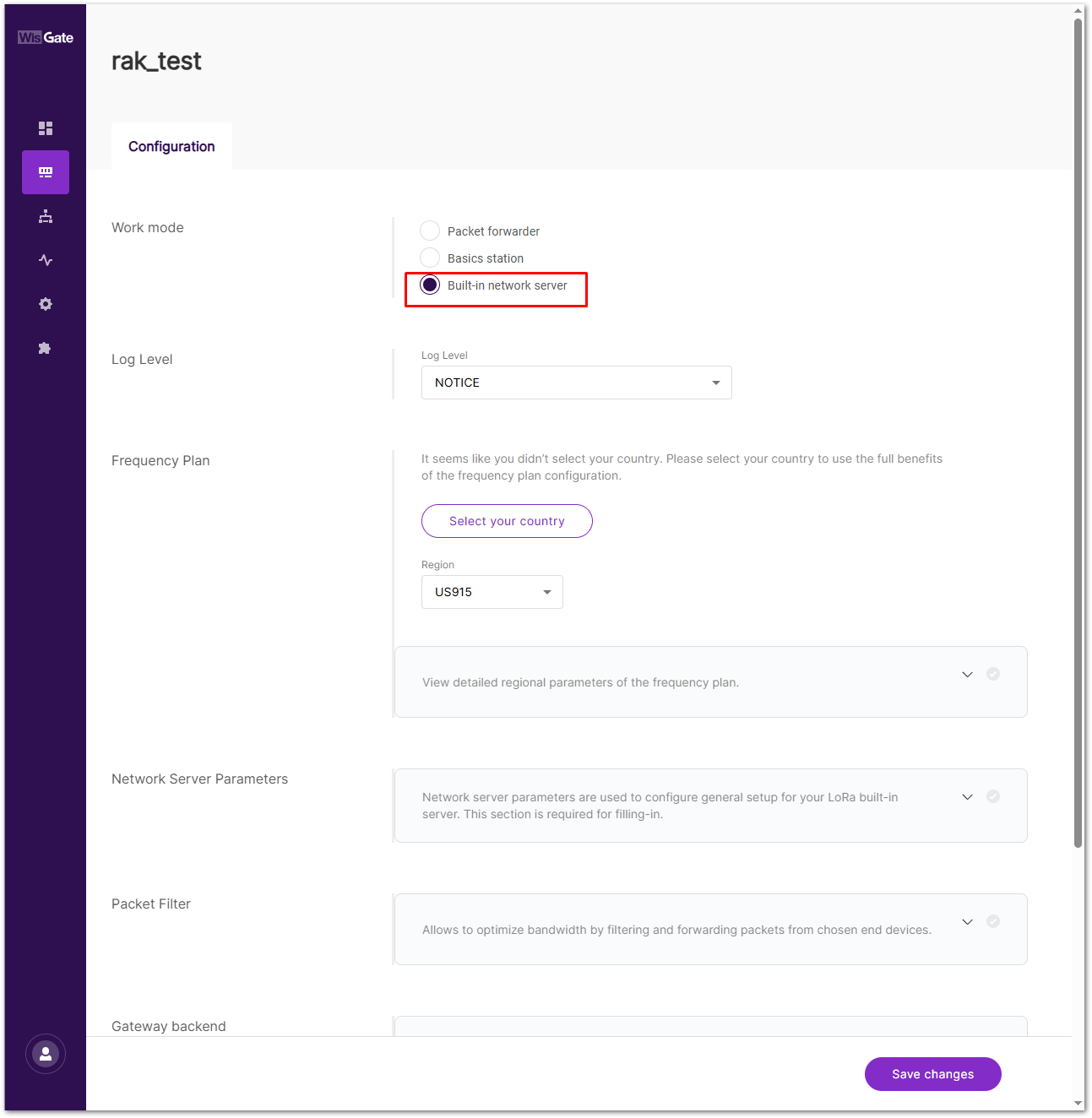 Figure 1: RAK7268V2 network server mode
- After configuring the gateway to use a built-in LoRaWAN network server (LNS), proceed to add an application to the network server and register a device. Click on the Applications tab, which will display all the LoRaWAN applications you currently have, then click on Add application button.
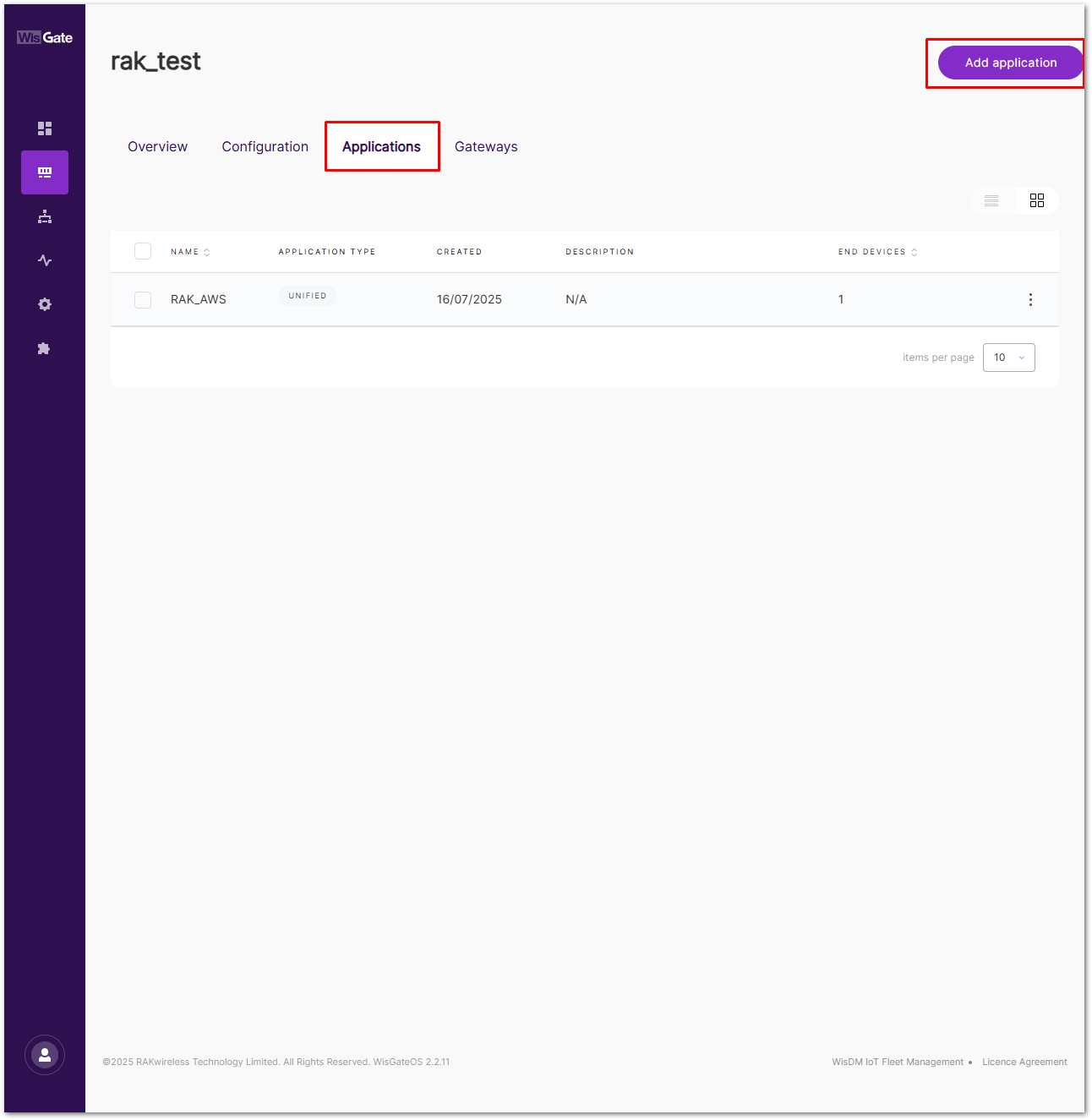 Figure 1: Accessing Application Console in the network server
- Ensure to assign a meaningful name to your application. For this illustration, RAK4630 Module, select Unified Application Key, then since is a essential parameter in a LoRaWAN application is the Application Key, utilized in OTAA activation. Click Autogenerate. After the configuration, click Save application to proceed with the end device setup.
While you can manually add an Application Key, it's advisable to let the network server generate it.
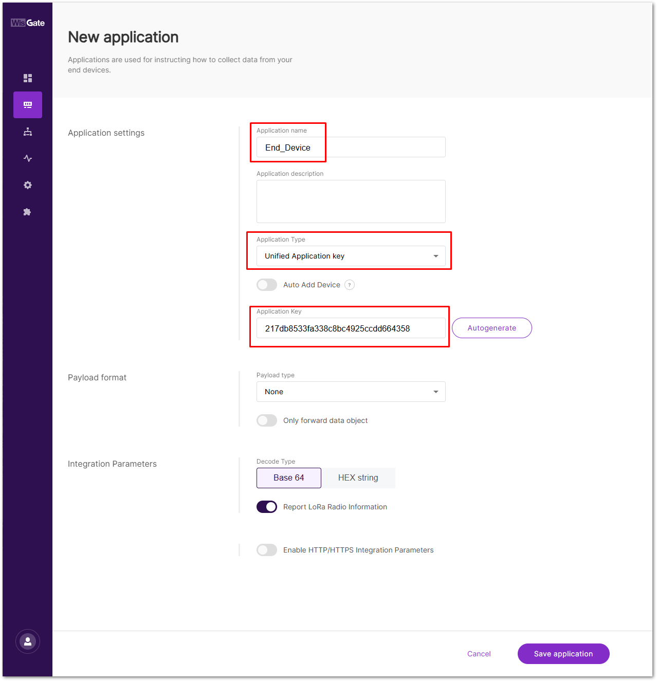 Figure 1: Adding Application to the LoRaWAN network server
- To register the WisDuo module as a device in that application, click on the End devices tab and then on the Add end device button.
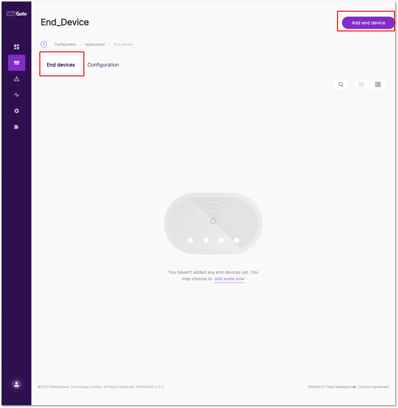 Figure 1: Access the LoRaWAN Application Console
- Put a name on your device, in this case, WisDuo Module. Three parameters in this list must be the same as your WisDUO Module code: Class, Activation Mode, and Application Key, Click on the Add en device button to continue.
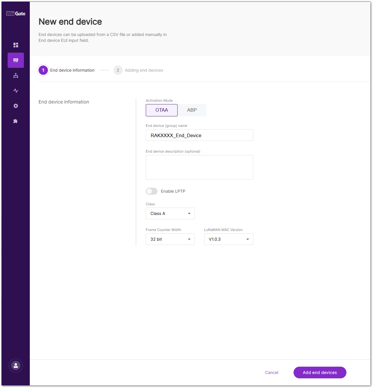 Figure 1: Adding device to the application
- Add the device EUI (DEVEUI) on the application console. This must be unique, and it is highly encouraged that you use the DEVEUI printed on the sticker of your WisNode Module module. Then click the Add to End Device List button to complete the setup.
In the Arduino code example in the latter part of this guide, Class A and Join Mode OTAA are the default. With that, you will only need to modify the code of the application key. Lastly, the LoRaWAN MAC Version must be 1.0.3. After setting up all these parameters, click Save & Apply.
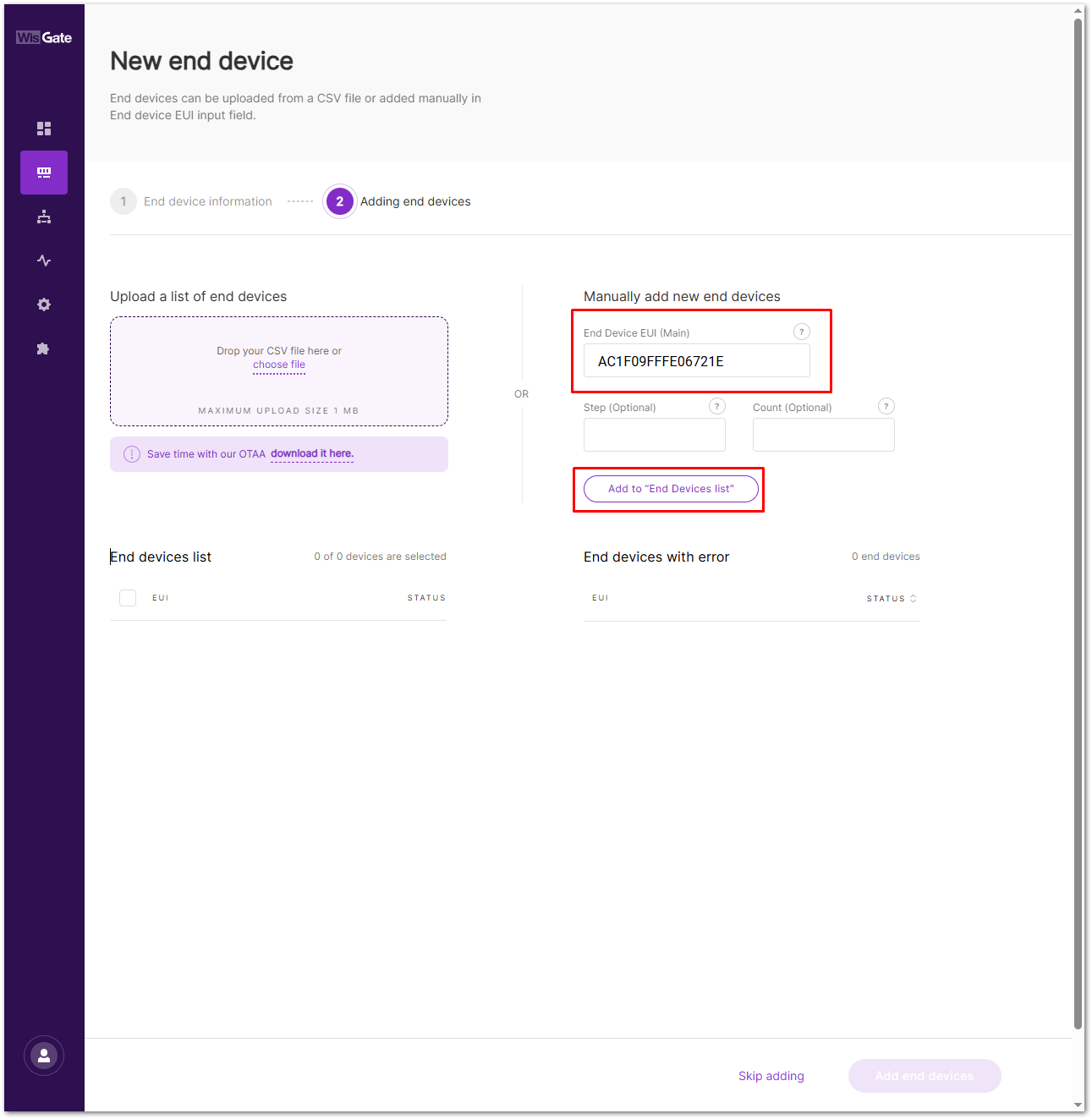 Figure 1: Configuration of the WisNode Module as OTAA device
- The device will now be shown in the End devices list. The next step is to prepare the WisDuo module so that it can match all the parameters in the network server.
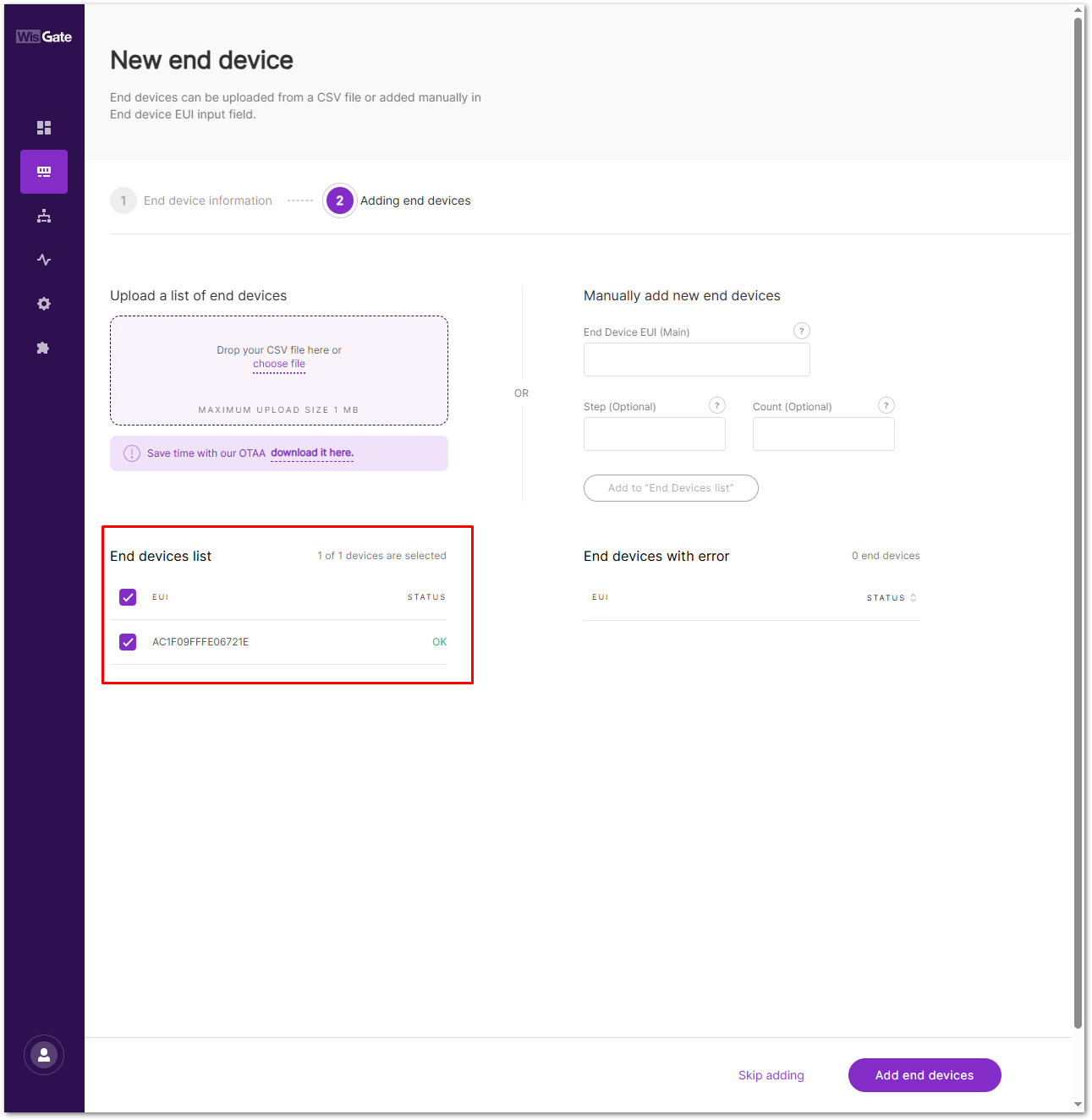 Figure 1: WisNode Module registered on the network server
Upload the LoRaWAN Example to RAK4630
After successfully registering the module to the LoRaWAN Network Server as an OTAA device, you can proceed with running the LoRaWAN OTAA demo application example.
- Open the example code under RAK WisBlock RUI examples.
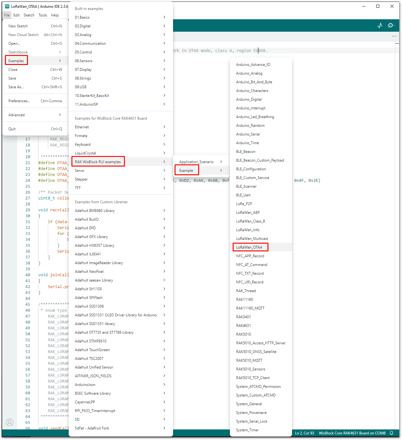 Figure 1: OTAA LoRaWAN application example
- In the example code, modify the device EUI (DEVEUI) and application key (APPKEY).
- The device EUI (DEVEUI) must match the DevEUI registered on your LoRaWAN network server in the previous section. The DEVEUI is MSB.
 // Example OTAA Device EUI MSB
  #define OTAA_DEVEUI   {0xAC, 0x1F, 0x09, 0xFF, 0xFE, 0x06, 0x72, 0x1E}
- Another important parameter to change is the application key (APPKEY). This parameter must match the AppKey configured on your LoRaWAN network server in the previous section. The APPKEY is MSB.
// Example OTAA Application Key MSB
  #define OTAA_APPKEY   {0x21, 0x7D, 0xB8, 0x53, 0x3F, 0xA3, 0x38, 0xC8, 0xBC, 0x49, 0x25, 0xCC, 0xDD, 0x66, 0x43, 0x58}
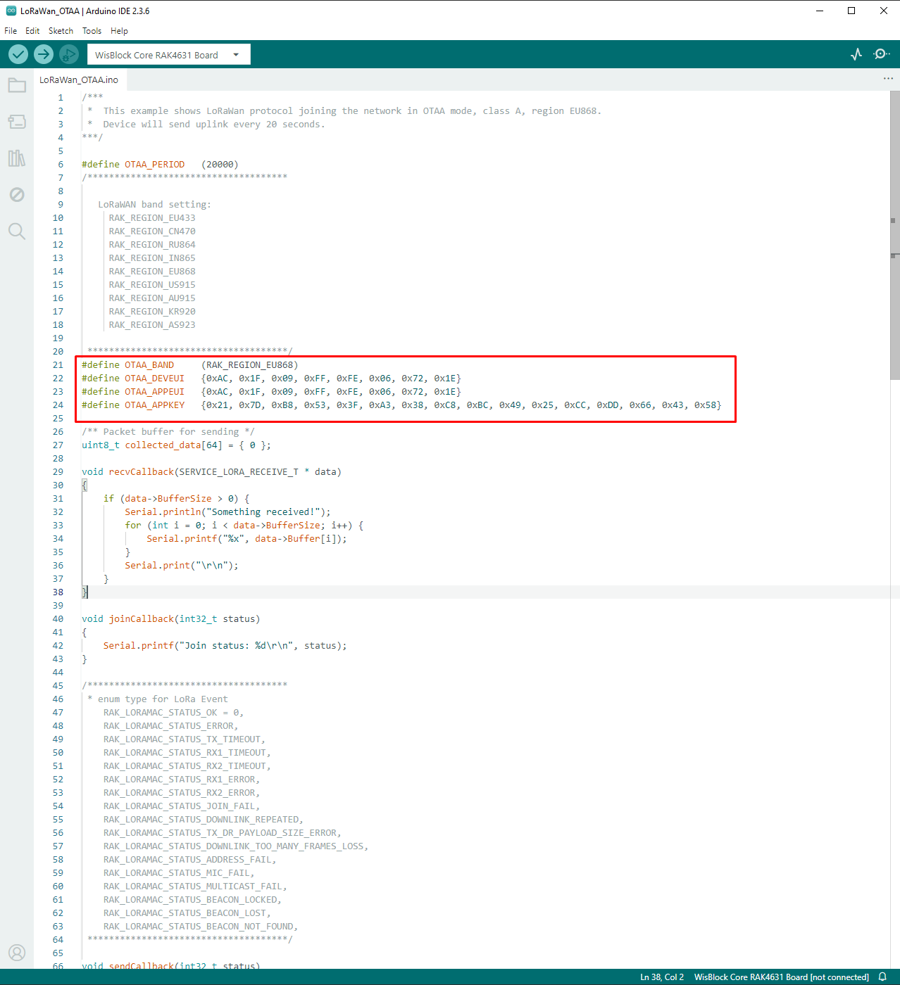 Figure 1: Updating DEVEUI and APPKEY
- This guide uses US915 regional band, so you need to update the band in the code as well. Additionally, set up the channel mask (channels 8 to 15 are the most commonly used channels in the US915 band).
  if(!(ret = api.lorawan.band.set(5)))
  {
       Serial.printf("LoRaWan OTAA - set band is incorrect! \r\n");
       return;
  }

  uint16_t maskBuff = 0x0002;
  api.lorawan.mask.set(&maskBuff);
The supported regions are as follows:
- RAK_REGION_EU433 = 0
- RAK_REGION_CN470 = 1
- RAK_REGION_RU864 = 2
- RAK_REGION_IN865 = 3
- RAK_REGION_EU868 = 4
- RAK_REGION_US915 = 5
- RAK_REGION_AU915 = 6
- RAK_REGION_KR920 = 7
- RAK_REGION_AS923-1 = 8
- RAK_REGION_AS923-2 = 9
- RAK_REGION_AS923-3 = 10
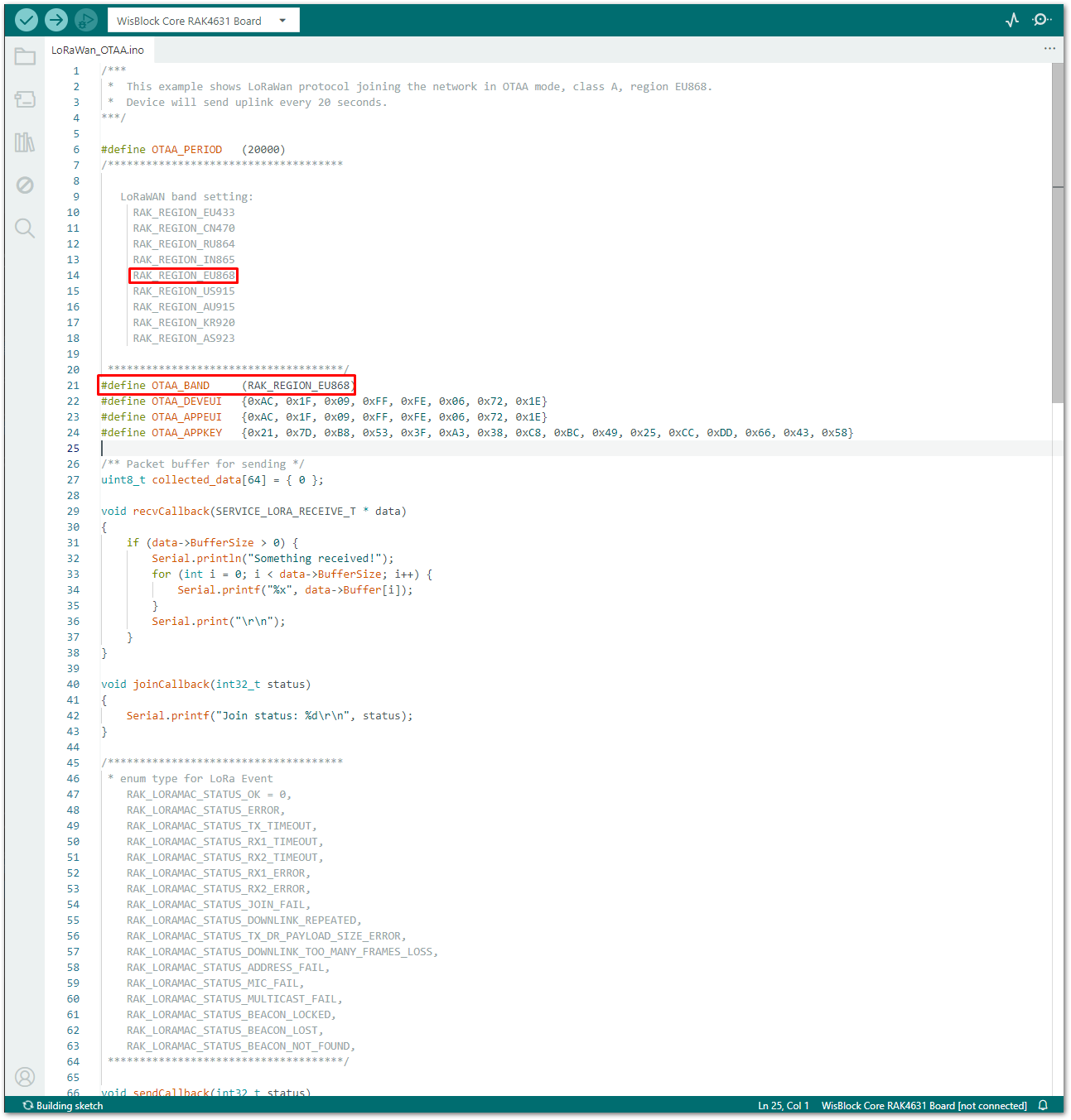 Figure 1: Updating to US915 and setting up channel mask
- The last step is to upload the code by clicking the Upload icon. Take note that you should select the right board and port.
The module should automatically go to BOOT mode when the firmware is uploaded via Arduino IDE. If BOOT mode is not initiated, you can manually send AT+BOOT command to start bootloader mode.
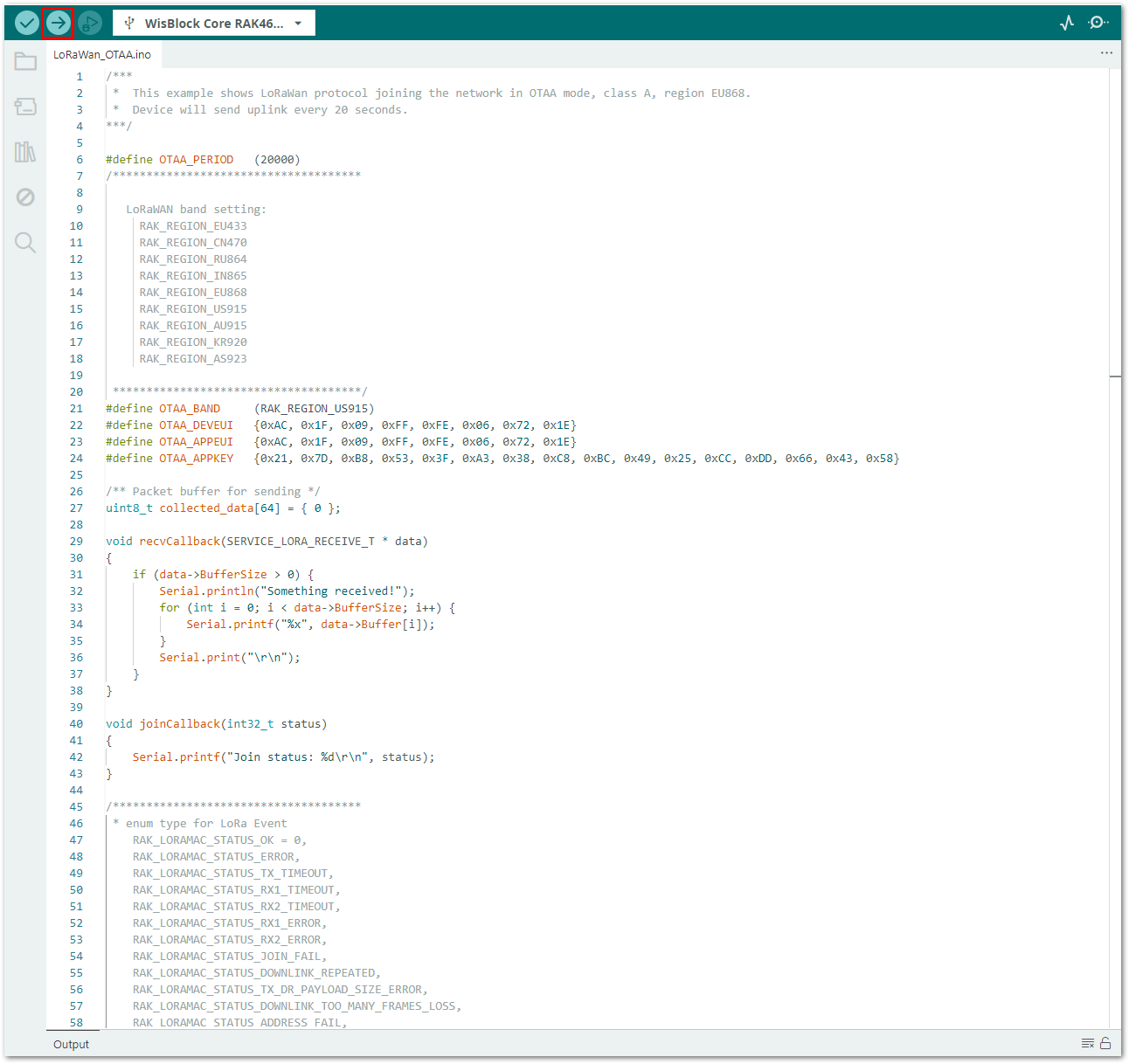 Figure 1: Uploading the code
- You should now be able to view the terminal logs in the Serial Monitor of the Arduino IDE. There are times the COM port may be disconnected, preventing you from viewing of the terminal output immediately. In such cases, you can reconnect the module or try pressing the reset button to see the terminal output.
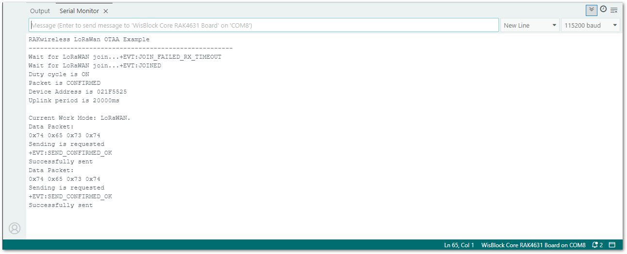 Figure 1: Output logs
- You can also check on the LoRaWAN network server if your device has been successfully joined with the
join requestandjoin acceptlogs.
More examples for the WisNode Module can be found in the RUI3-Best-Practices on Github.


