index
- Open the Serial terminal like the RAK Serial Port Tool. Select the right COM port and set the baud rate to 115200.
It is recommended to start by testing the serial communication and verify that the current configuration is working by sending these two AT commands:
AT
ATE
ATE will echo the commands you input to the module, which is useful for tracking the commands and troubleshooting.
You will receive OK when you input the two commands. After setting ATE, see all the commands you input together with the replies. Try again AT and you should see it on the terminal followed by OK.
If you haven't received an OK or any reply, you need to check if the wiring of your UART lines is correct and if the baud is correctly configured to 115200. Also, you can check if the device is powered correctly. If you are getting power from a USB port, ensure that you have a good USB cable.
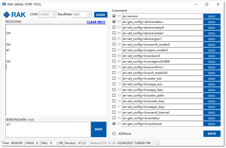 Figure 1: at+version command response
- The next step is to configure the OTAA LoRaWAN parameters in the module:
Set the work mode to LoRaWAN. You might need to reconnect on the Serial Terminal Software Tool if you lost connection after using the AT+NWM=1 command.
AT+NWM=1
Set the LoRaWAN activation to OTAA.
AT+NJM=1
Set the LoRaWAN class to Class A.
AT+CLASS=A
Set the frequency/region to EU868.
AT+BAND=4
Depending on the Regional Band you selected, you might need to configure the sub-band of your RAK end device to match the gateway and LoRaWAN network server. This is especially important for Regional Bands like US915, AU915, and CN470.
To configure the masking of channels for the sub-bands, you can use the AT+MASK command that can be found on the AT Command Manual.
To illustrate, you can use sub-band 2 by sending the command AT+MASK=0002.
List of band parameter options
| Code | Regional Band |
|---|---|
| 0 | EU433 |
| 1 | CN470 |
| 2 | RU864 |
| 3 | IN865 |
| 4 | EU868 |
| 5 | US915 |
| 6 | AU915 |
| 7 | KR920 |
| 8 | AS923 |
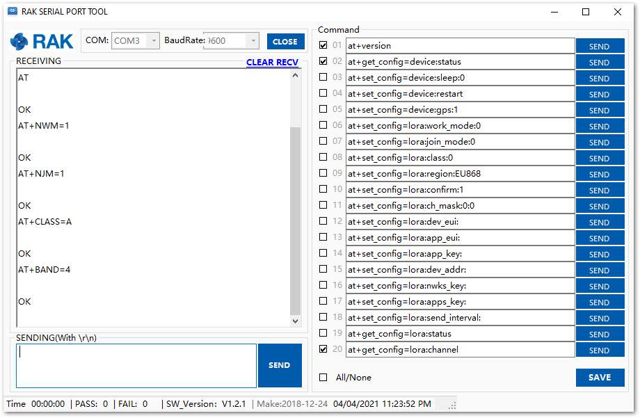 Figure 1: Configuring LoRa parameters
- Set up the EUIs and key. You need to use the values from the TTN console you configured in the earlier steps, the values shown are examples.
The Application EUI parameter is not required in the ChirpStack platform; therefore, it is possible to use the same id as the Device EUI.
Set the Device EUI.
AT+DEVEUI=5E9D1E0857CF25F1
Set the Application EUI.
AT+APPEUI=5E9D1E0857CF25F1
Set the Application Key.
AT+APPKEY=F921D50CD7D02EE3C5E6142154F274B2
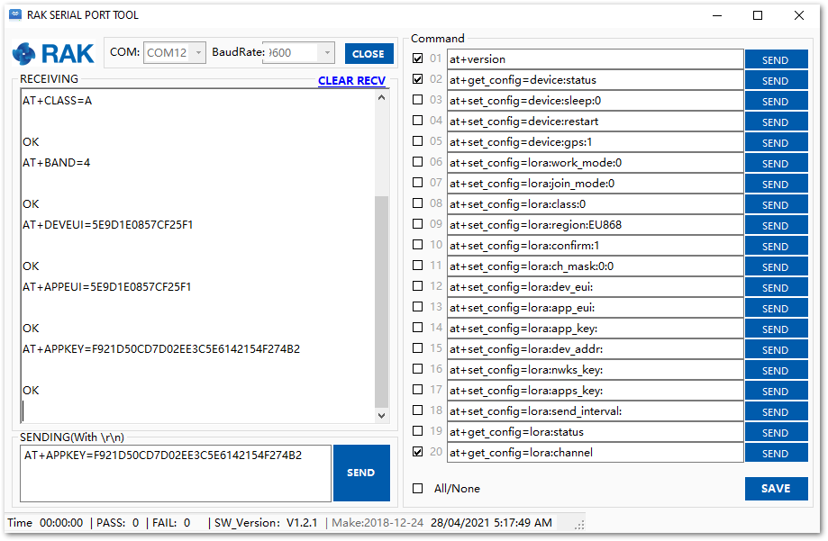 Figure 1: Configuring LoRa Parameters
- After the EUI and key configuration, the device can now join the network and send some payload. Join command format:
AT+JOIN=w:x:y:z
AT+JOIN=1:0:10:8
| Parameter | Description |
|---|---|
| w | Join command - 1: joining, 0: stop joining. |
| x | Auto-join config - 1: auto-join on power-up, 0: no auto-join |
| y | Reattempt interval in seconds (7-255) - 8 is the default. |
| z | Number of join attempts (0-255) - 0 is default. |
After 5 or 6 seconds, if the request is successfully received by a LoRa gateway, you should see the JOINED status reply.
If the OTAA device failed to join, check if your device is within reach of a working LoRaWAN gateway that is configured to connect to Chirpstack. It is also important to check that all your OTAA parameters (DEVEUI and APPKEY) are correct, using the AT+DEVEUI=? and AT+APPKEY=? commands. Lastly, ensure that the antenna of your device is properly connected.
After checking all the things above, try to join again.
- With the end-device properly activated, try to send some payload after a successful join. Send command format:
AT+SEND=<port>:<payload>
AT+SEND=2:12345678
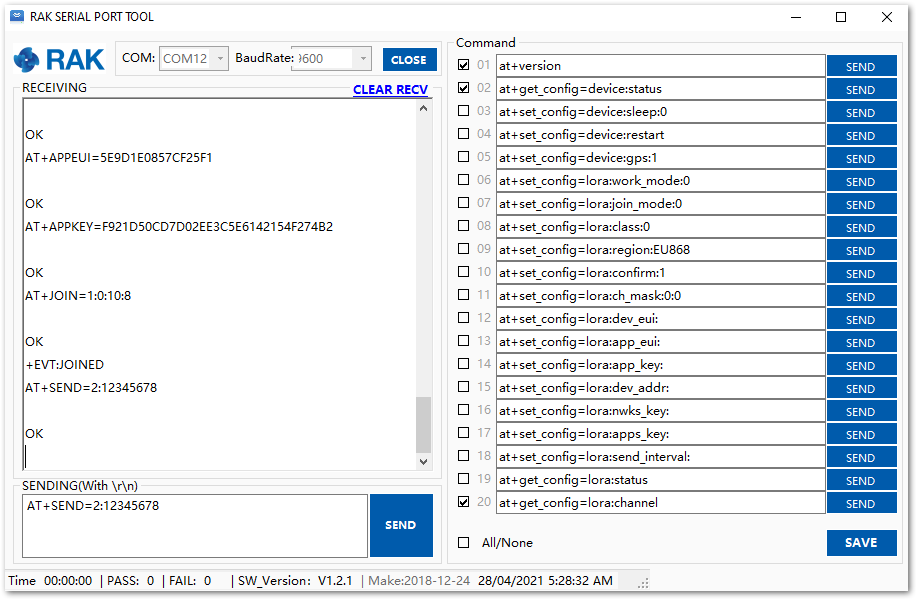 Figure 1: OTAA test sample data sent via RAK Serial Port Tool
On the ChirpStack platform, you should see the join and uplink messages in the LORAWAN FRAMES tab. By convention, messages sent from nodes to gateways are considered as Uplinks while messages sent by gateways to nodes are considered as Downlinks.
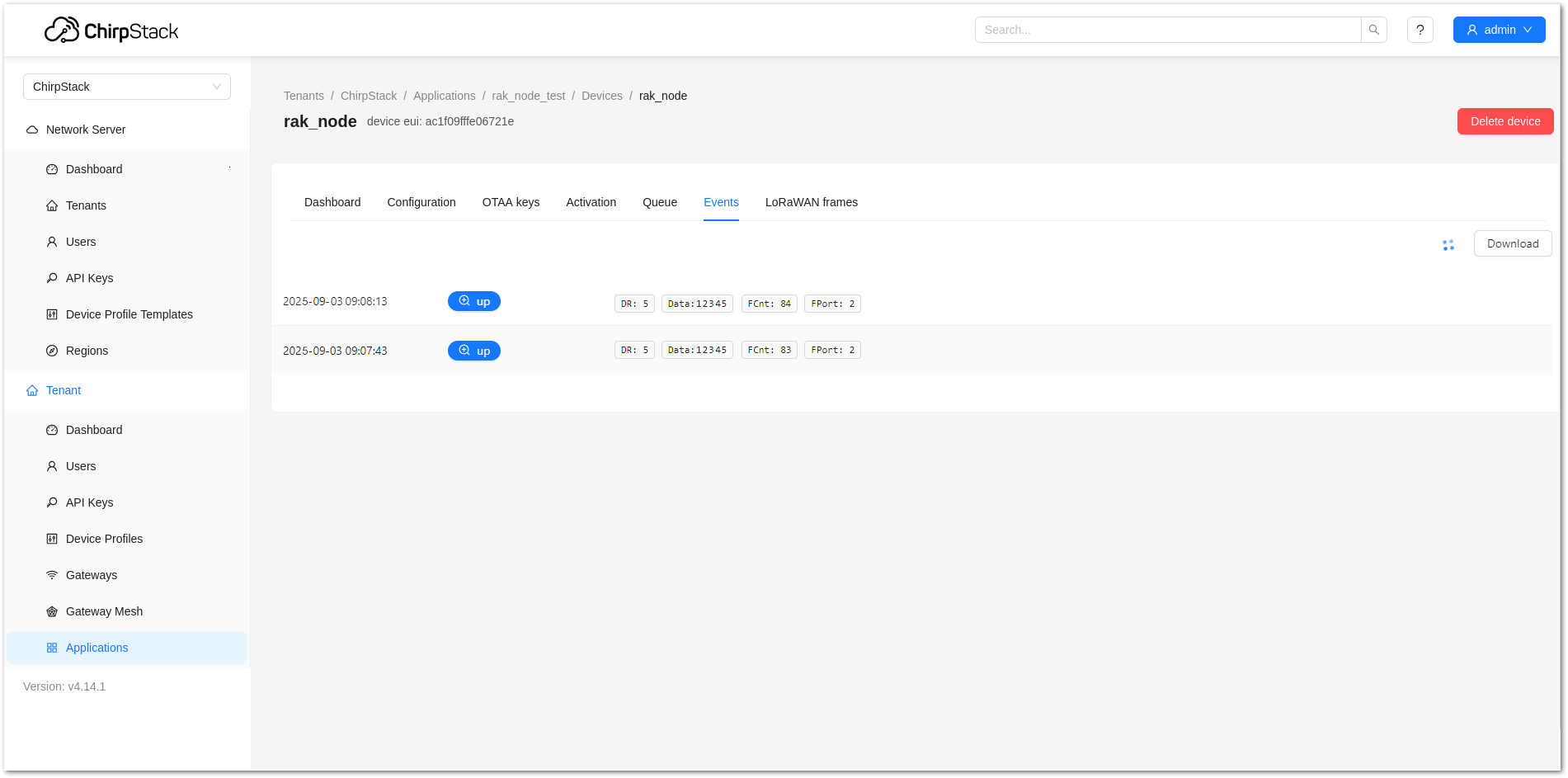 Figure 1: Chirpstack data received preview


