DI/DO Configuration
DI/DO interfaces refer to Digital Input (DI) and Digital Output (DO) interfaces. They are used to connect external digital signal devices for switch signal acquisition and control. By configuring the DI/DO interfaces, users can monitor the switch status of external equipment (DI) or control actuators such as relays and indicator lights (DO).
Digital Input Interface
The Digital Input (DI) interface receives external digital signals, such as switch status and sensor trigger signals.
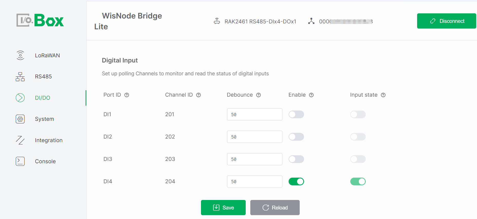 Figure 1: Digital Input configuration
Digital Input Setup
- Navigate to the DI/DO module and select the Digital Input menu.
- Turn on the Enable switch, keep the remaining parameters at default values, then click Save to apply the configuration.
- Trigger an external input and check if the Input State updates accordingly.
Digital Input Parameters
- Port ID: Identifies the physical DI port, corresponding one-to-one with the Bridge I/O hardware interface. Automatically assigned by the system and cannot be modified.
- Channel ID: Uniquely identifies the input channel within the system for data reporting and logical processing. Automatically assigned by the system and cannot be modified. Used in LoRaWAN or system data frames.
- Debounce: Prevents false triggering due to mechanical switch bouncing. Sets the signal stabilization time, only signals stable beyond this duration are considered valid inputs. (Unit: milliseconds).
- Enable: Enables or disables the input channel. Controls whether the input channel participates in polling and data reporting. Monitoring occurs only when enabled. Default: disabled.
- Input State: Displays the real-time input level status (high or low) of the port. The status updates in real-time when a valid signal is input from the external device. Read-only.
NOTE
This parameter is active only when Enable is ON.
Digital Output Interface
The DO interface outputs digital control signals to external devices, such as controlling relay switching or indicator light states.
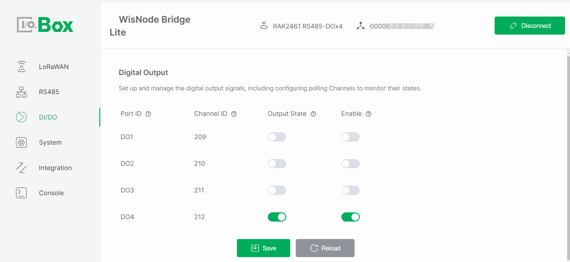 Figure 1: Digital Output configuration
Digital Output Setup
- Navigate to the DI/DO module and select the Digital Output menu.
- Turn on the Enable switch, set the desired Output State, and click Save to apply the configuration.
- Observe whether the actuator operates as expected.
Digital Output Parameters��
- Port ID: Identifies the physical DO port, corresponding one-to-one with the Bridge I/O hardware interface. Automatically assigned by the system and cannot be modified.
- Channel ID: Uniquely identifies the output channel within the system for command issuance and status tracking. Automatically assigned by the system and cannot be modified. Used as an address identifier in control commands or data frames.
- Output State: Controls the output level (high or low) of the port for controlling external devices. The state changes according to system or user commands. Writable parameter.
NOTE
This parameter is active only when Enable is ON.
- Enable: Enable or Disable the output channel. The Output State takes effect only when enabled. Default: disabled.