RAK13001 with RAK11310 WisBlock Core Guide
- First, you need to select the RAK11310 WisBlock Core.
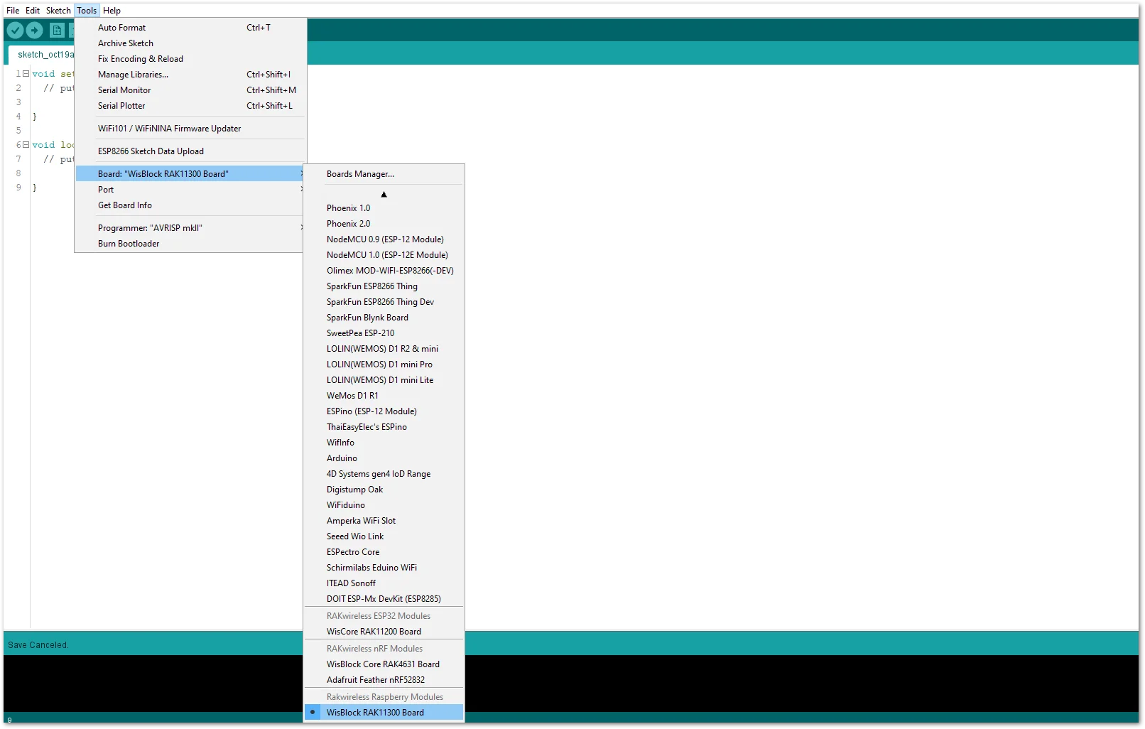 Figure 1: Selecting RAK11310 as WisBlock Core
- Next, copy the following sample code into your Arduino IDE:
Click to view the code
/**
   @file RAK13001_Relay_OUT_Optocoupled_IN.ino
   @author rakwireless.com
   @brief Relay output optocoupler input.
   @version 0.1
   @date 2021-3-18
   @copyright Copyright (c) 2021
**/

#define OC_PIN    WB_IO3
#define RELAY_PIN WB_IO4

void setup()
{
  pinMode(WB_IO2, OUTPUT);
  digitalWrite(WB_IO2, HIGH);

  // Initialize Serial for debug output
  time_t timeout = millis();
  Serial.begin(115200);
  while (!Serial)
  {
    if ((millis() - timeout) < 5000)
    {
      delay(100);
    }
    else
    {
      break;
    }
  }

  pinMode(RELAY_PIN,OUTPUT);
  pinMode(OC_PIN,INPUT);
}

void loop()
{
  static uint8_t count=0;
  count++;
  if(count == 5)
  {
    digitalWrite( RELAY_PIN , LOW);
  }
  if(count == 10)
  {
    count=0;
    digitalWrite( RELAY_PIN , HIGH);
  }

  if(digitalRead(OC_PIN) == LOW)
  {
    Serial.println("Optocoupled PIN IN Low");
  }

  delay(1000);
}
NOTE
If you experience any error in compiling the example sketch, check the updated code for your WisBlock Core Module that can be found on the RAK13001 WisBlock Example Code Repository.
- Then you can now select the right port and upload the code.
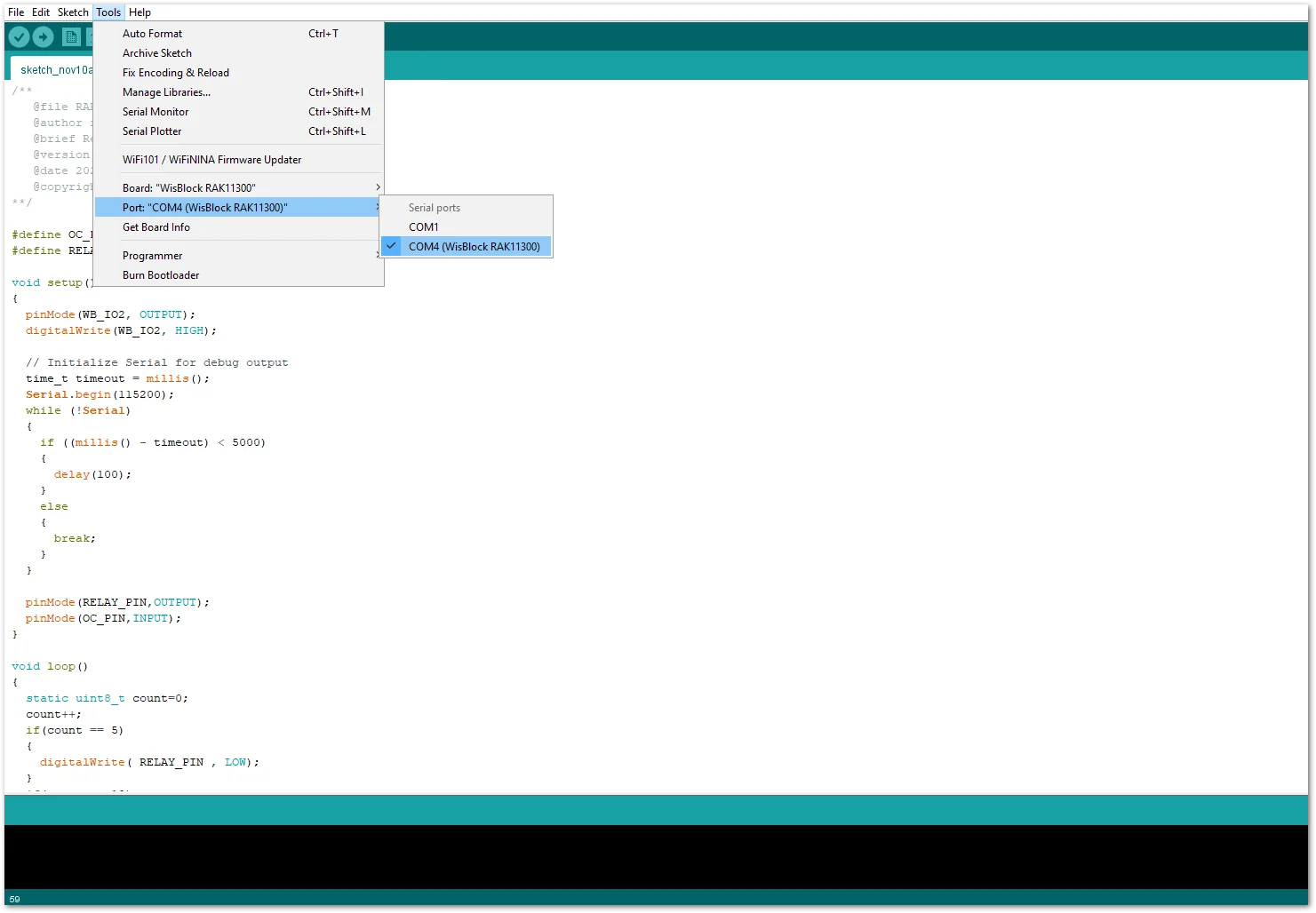 Figure 1: Selecting the correct Serial Port
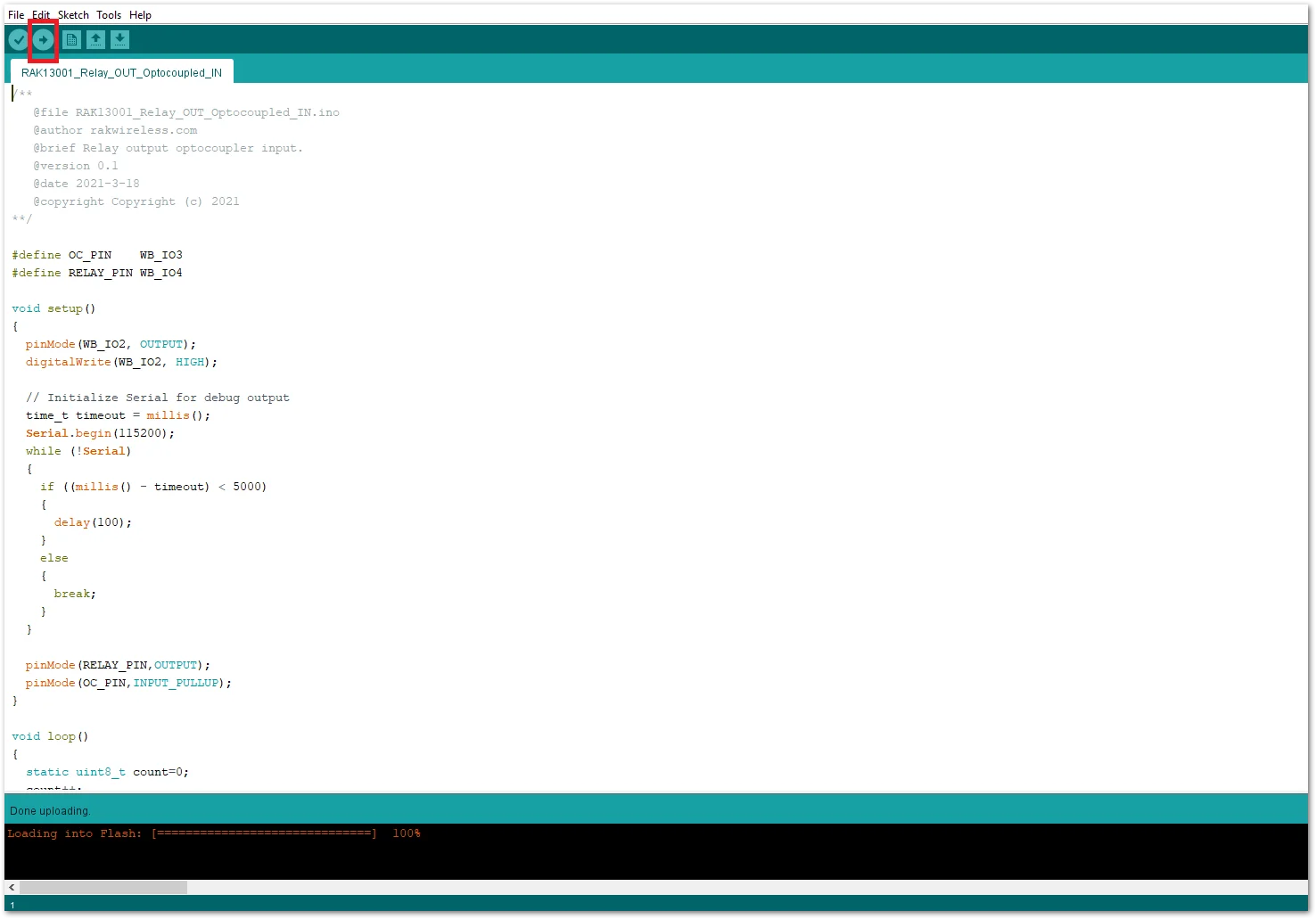 Figure 1: Uploading the RAK13001 Sample code
- When you successfully uploaded the example sketch, you'll now be to see that the RAK13001 Relay module switches the LED on and off every 5 seconds. You'll also be able to hear clicking sounds from the RAK13001 module which means that the relay is switching.


