RAK13302 WisBlock LPWAN Wireless Module Installation Guide
- This documentation is for the board version VD. There is one main difference between this version and the older version VC.
- The board version VC allowed switching between an external 5 V power supply and an internal battery supply using a jumper.
- With board version VD, this switching option is no longer available. Version VD is available in two variants:
- One only works with an external 5 V power supply.
- The other only works with an internal battery supply.
Make sure to order the correct hardware version for your requirements.
Prerequisites
The modules required before installation include:
- RAK13302
- Your choice of WisBlock Base
- RAK3401 WisBlock Core
- RAK3401 WisBlock Core (Only available as WisMesh High Power Booster Starter Kit)
The RAK13302 can only be used with the WisBlock Core modules RAK3401. Other WisBlock Core modules already have an integrated LoRa transceiver.
WisBlock Module Installation
The RAK13302 Wireless module integrates with WisBlock Core modules without a built-in LoRa radio chip, such as the RAK3401. It extends WisBlock applications with LoRa P2P and LoRaWAN connectivity.
RAK13302 module can be mounted to the IO slot of the WisBlock Base and communicated to the WisBlock Core via SPI. The module is activated via WB_IO2 pin of the WisBlock Core.
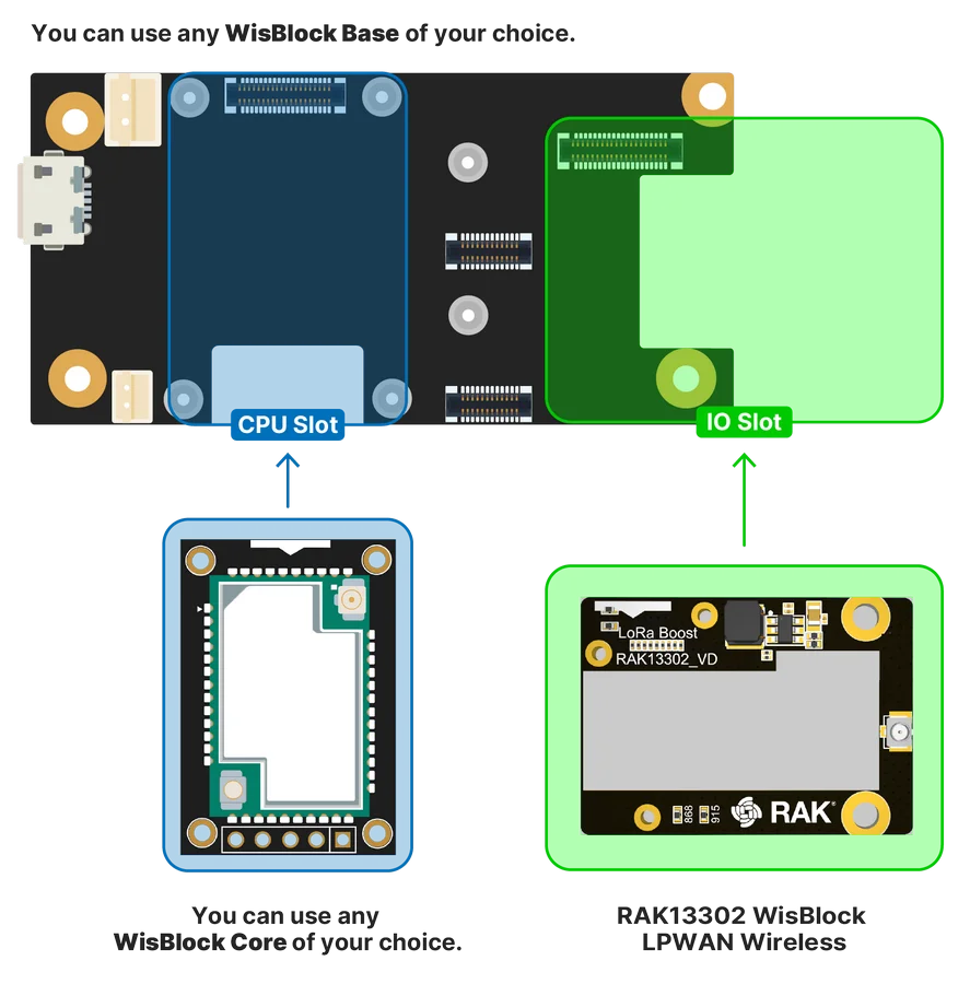 Figure 1: RAK13302 connection to WisBlock Base
Assemble WisBlock Modules
The location of the IO Slot is properly marked by silkscreen. Follow carefully the procedure defined in WisBlock Base module assembly/disassembly instructions to attach a WisBlock module. Once attached, carefully fix the module with one or more pieces of M1.2 x 3 mm screws depending on the module.
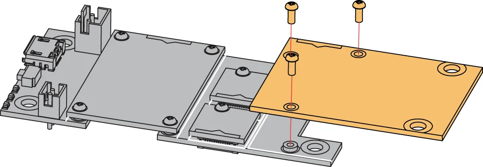 Figure 1: RAK13302 Wireless Module mounting mechanism
LoRa Antenna
The RAK13302 requires a LoRa Antenna to have a good signal. Do not power the module without an antenna connected to the IPEX connector, as this can damage the RF section of the chip.
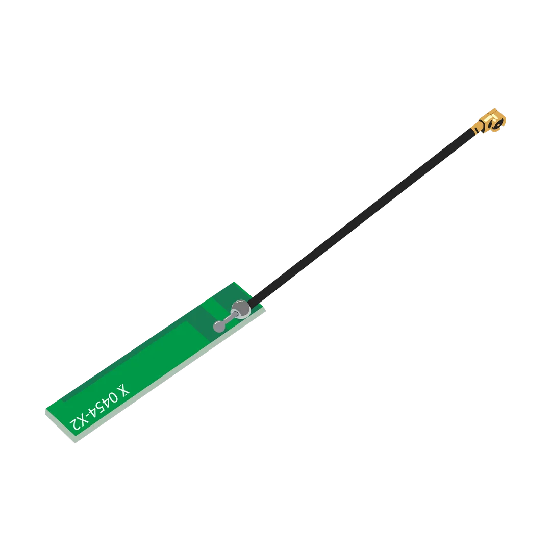 Figure 1: LoRa Antenna
Detailed information about the LoRa antenna can be found on the LoRa Antenna Datasheet.
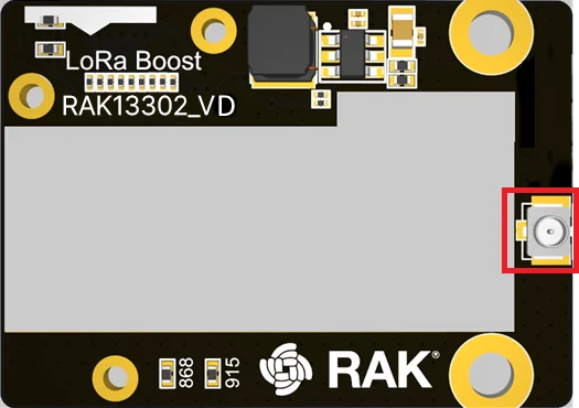 Figure 1: RAK13302 Antenna Slot
To avoid damage, always connect an antenna when using LoRa transceivers. Use screws to keep the module firmly in place for proper operation.
Power Supply Variants
The RAK13302 version VD module has two hardware variants. One hardware variant only works with an external 5 V power supply, while the other only works with an internal battery supply. The different hardware versions are identified by different codes on the label.
The version for power supplied through the battery connected to the WisBlock Base Board has the code 001 on the label, and it has no connector for the external 5 V supply on the bottom of the PCB.
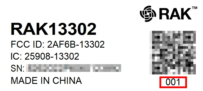 Figure 1: RAK13302 Wireless Module Battery Supply Indication
The version for supply with an external 5 V supply has the code 002 on the label. And it has the connector for the external 5 V supply on the bottom of the PCB.
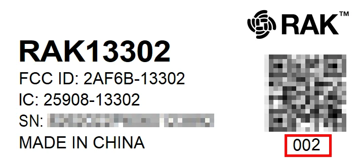 Figure 1: RAK13302 Wireless Module External 5 V Supply Indication
If the supply is through EX_5V, the whole WisBlock Base Board can be supplied through this source.
External 5 V Supply Connection
The connector for the external 5 V supply is on the bottom of the module.
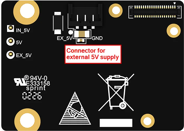 Figure 1: RAK13302 5 V supply connector
External power supply cable connections:
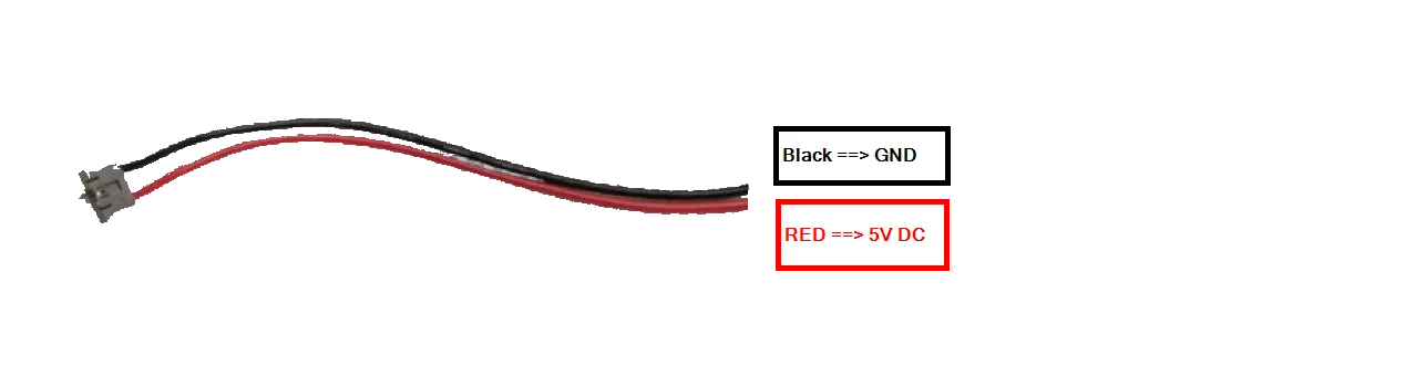 Figure 1: RAK13302 5 V supply selection
Battery Connection
If not using the external 5 V supply for the module, it is required to use a Li-Ion/LiPo battery via connectors. There are other WisBlock Base boards available, and you need to check the datasheet of the specific WisBlock Base board for the right polarity and parameters.
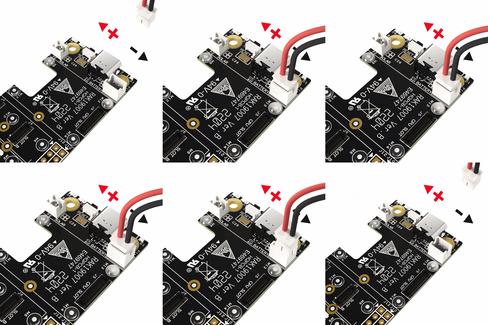 Figure 1: WisBlock Base battery polarity and connection


