RAK18061 WisBlock Audio Mono Amplifier Module Installation Guide
Prerequisite
The modules required before installation include:
- RAK18061 WisBlock Audio Mono Amplifier Module
- Your choice of WisBlock Base with IO slot
- Your choice of WisBlock Core
WisBlock Module Installation
RAK18061 is a mono amplifier module, part of the WisBlock Audio Series. It connects to the IO slot of the WisBlock Base to communicate with the WisBlock Core. Always secure the connection of the WisBlock module by using compatible screws.
Select a compatible WisBlock Base and WisBlock Core according to your needs.
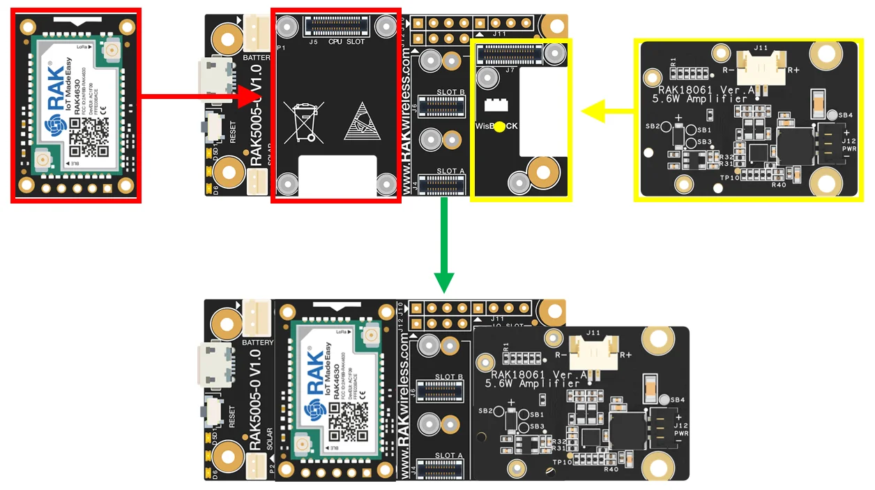 Figure 1: RAK18061 connection to WisBlock Base
Assembling and Disassembling of WisBlock Modules
Assembling
The location for the IO slot is properly marked by silkscreen. Follow carefully the procedure defined in WisBlock Base board assembly/disassembly instructions to attach a WisBlock module. Once attached, carefully fix the module with one or more pieces of M1.2 x 3 mm screws depending on the module.
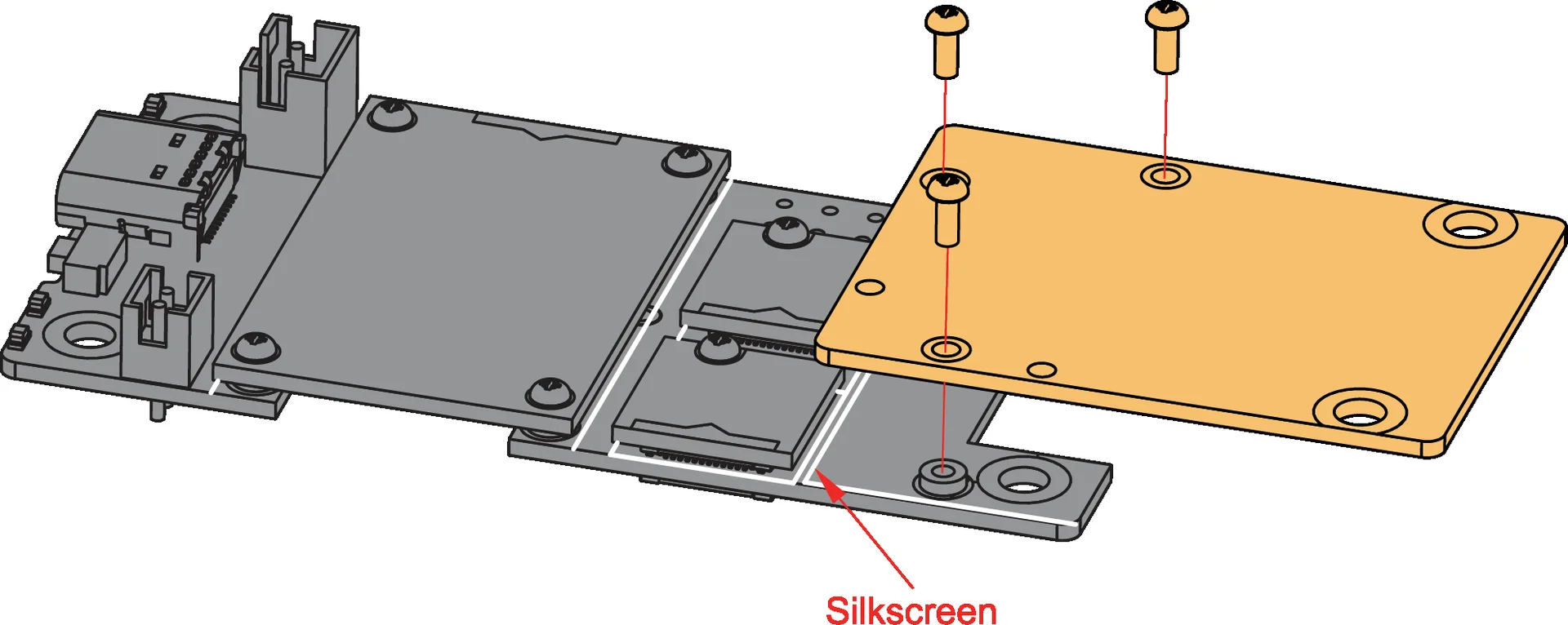 Figure 1: RAK18061 connection to WisBlock Base
You need to connect the LoRa and BLE antennas to the RAK4631 module to avoid damage to this module during operation.
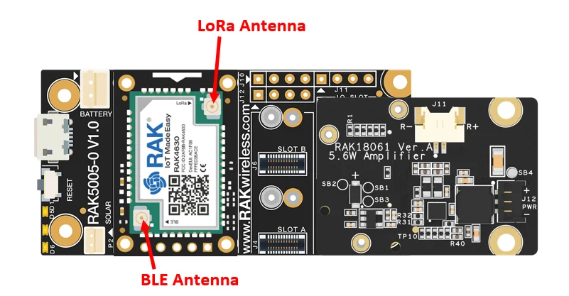 Figure 1: LoRa and BLE antennas connection to RAK4631 module
The RAK18061 module is powered via SB2 (battery) by default. If you wish to use other DC power source.
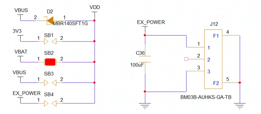 Figure 1: Power Select Diagram for RAK18061 with SB2 as default
3V3
If you want to use 3V3, desolder SB2 and solder SB1.
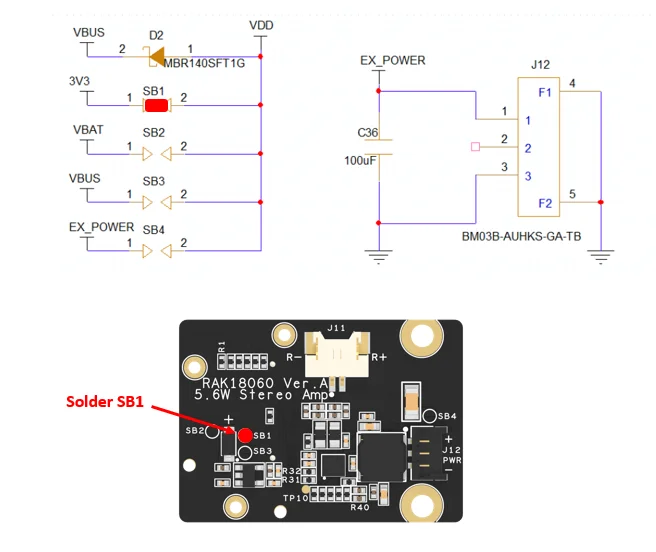 Figure 1: Solder portion for SB1
VBUS
If you want to use VBUS, desolder SB2 and solder SB3.
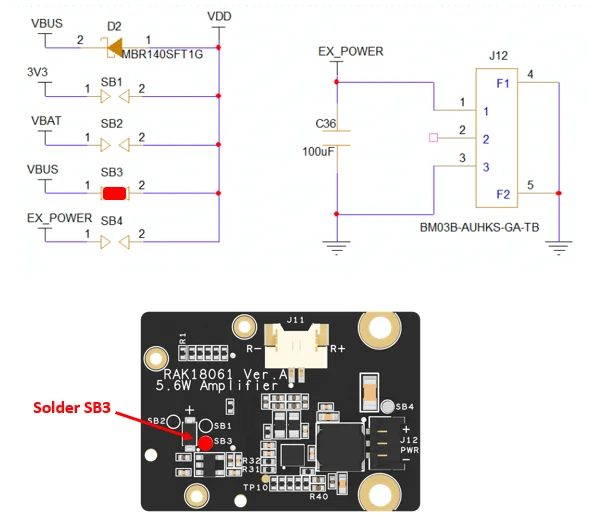 Figure 1: Solder portion for SB3
EX_POWER
If you want to use EX_POWER, desolder SB2 and solder SB4.
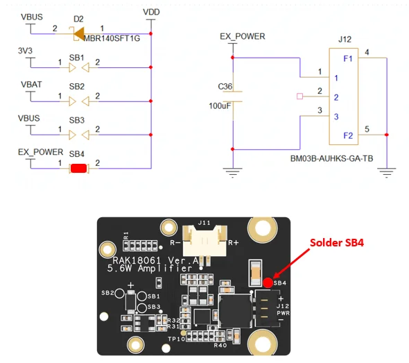 Figure 1: Solder portion for SB4
Then you can now connect the speaker to the speaker output of the RAK18061 module.
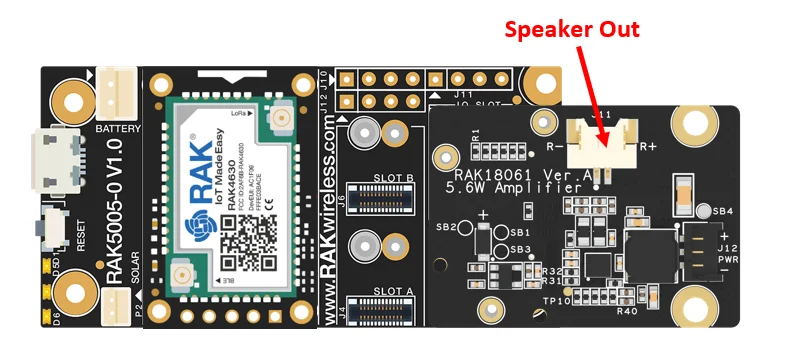 Figure 1: Speaker output of RAK18061 module
Disassembling
The procedure in disassembling any type of WisBlock modules is the same.
- First, remove the screws.
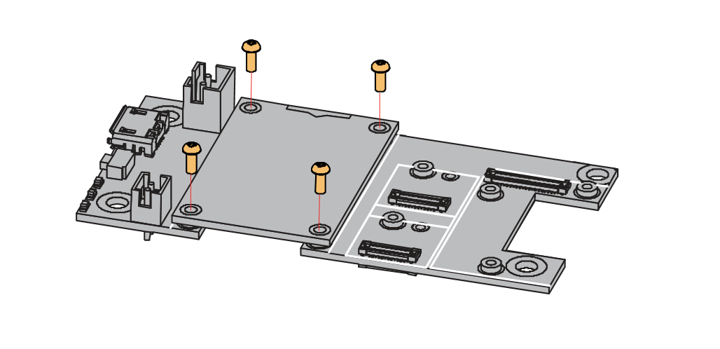 Figure 1: Removing screws from the WisBlock module
- Once the screws are removed, check the silkscreen of the module to find the correct location where force can be applied.
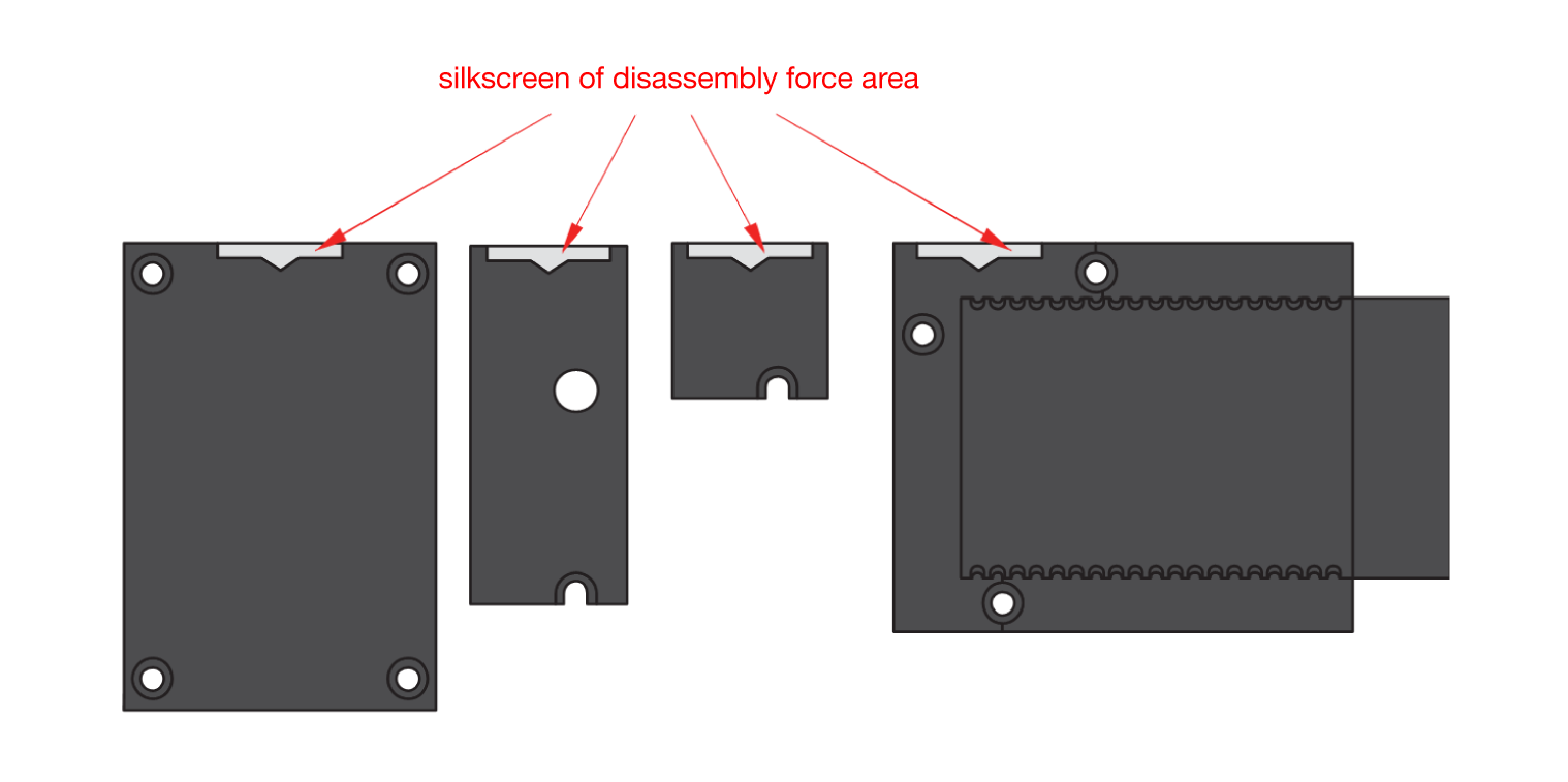 Figure 1: Finding the proper position to detach the WisBlock module
- Apply even force to the module at the position of the connector to detach the module from the WisBlock Base.
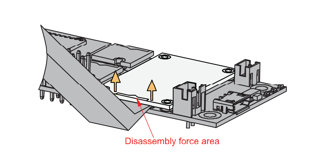 Figure 1: Applying even forces on the proper location of a WisBlock module
If you will connect other modules to the remaining WisBlock Base slots, check on the WisBlock Pin Mapper tool for possible conflicts.
After all this setup, you can now connect the battery (optional) and USB cable to start programming your WisBlock Core.
- Batteries can cause harm if not handled properly.
- Only 3.7-4.2 V Rechargeable LiPo batteries are supported. It is highly recommended not to use other types of batteries with the system unless you know what you are doing.
- If a non-rechargeable battery is used, it has to be unplugged first before connecting the USB cable to the USB port of the board to configure the device. Not doing so might damage the battery or cause a fire.
- Only 5 V solar panels are supported. Do not use 12 V solar panels. It will destroy the charging unit and eventually other electronic parts.
- Make sure the battery wires match the polarity on the WisBlock Base board. Not all batteries have the same wiring.


