RAK19001 WisBlock Dual IO Base Board Installation Guide
RAK19001 WisBlock Base Board is the main board that allows you to attach MCU, sensors, and IO modules through the standardized expansion connectors. These connectors provide a data bus interconnection between the modules attached to the RAK19001 Base Board.
This guide shows the details related to the installation of modules into the RAK19001 Base board.
WisBlock WisConnector Installation
Attaching a WisConnector
The WisConnector is the interface between the Wisblock Base module and the WisBlock Core, Sensor, and IO modules. Before connecting these modules, read the following instructions:
This guide uses two arrows. Refer to Figure 2 for its representation.
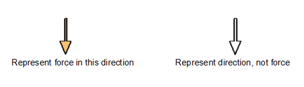 Figure 1: Notation within the guide
- Align the connectors. Keep the header parallel and place it lightly in the corresponding lap joint of the socket.
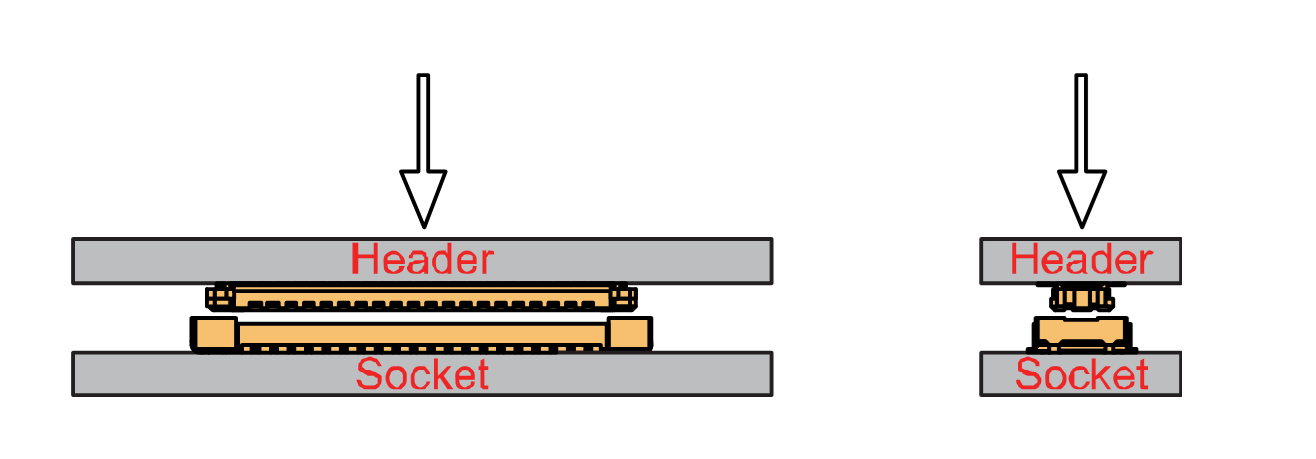 Figure 1: Alignment of WisConnector
- Fit the connector. Tilt one end of the connector (header) less than 20 degrees, while do not apply force during this process, gently place the other end in parallel.
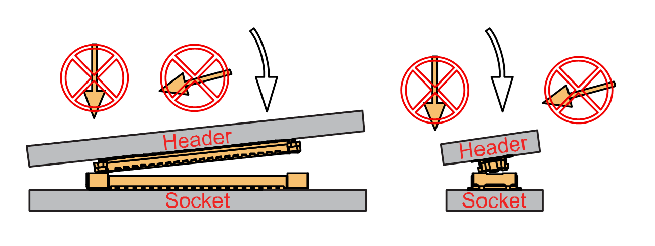 Figure 1: Fit the WisConnector’s header inside of the socket
- After the above alignment steps, the header and socket are matched but still not buckled.
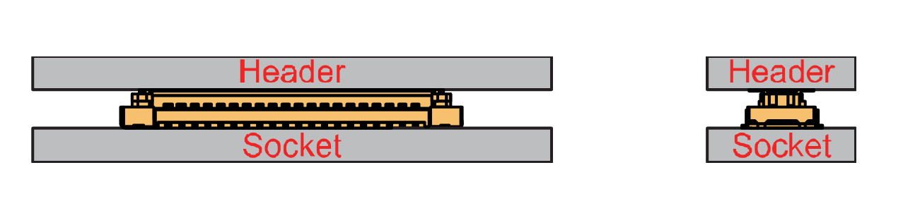 Figure 1: WisConnector’s header matched inside of the socket
- Apply forces evenly by pressing in parallel, then there will be a sound confirming the completion of the buckling.
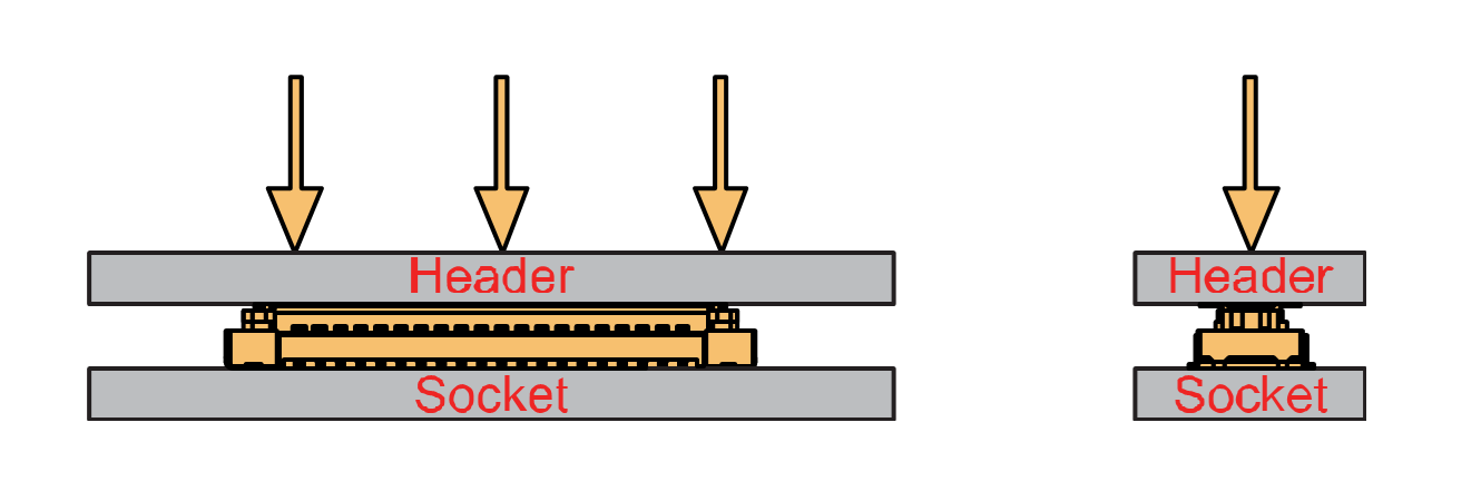 Figure 1: Apply forces to buckle the heard to the socket
- In the process of buckling and applying force, avoid the application of uneven force on both sides.
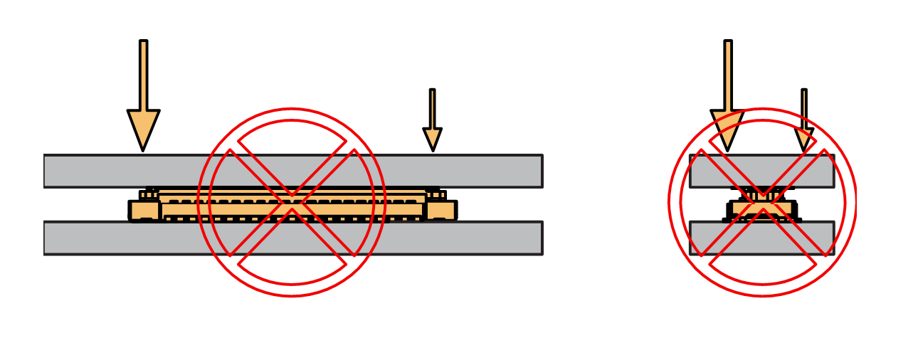 Figure 1: Avoid applying uneven forces
- When the buckling process is completed, check that the header and socket are kept in parallel.
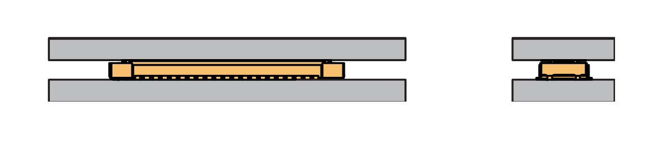 Figure 1: Correct way to buckle the WisConnector’s header to the socket
- If after buckling, the header and socket are not in a parallel state (not fully assembled in one place), then press the even force on both sides of the long side to complete the correct buckling.
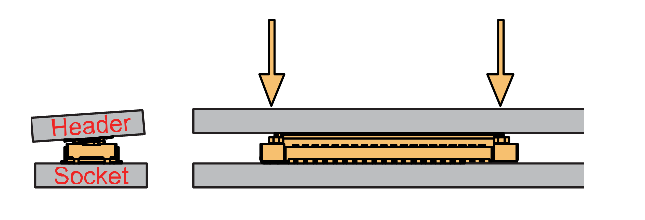 Figure 1: WisConnector’s header is not parallel to the socket
- When the aforementioned steps are not completed yet, do not apply force to buckle. Otherwise, there will be a risk to damage the connector. When the connector cannot be smoothly buckled down, repeat the alignment step.
Detaching a WisConnector
- To disconnect the header from the socket, pull out in parallel with even forces.
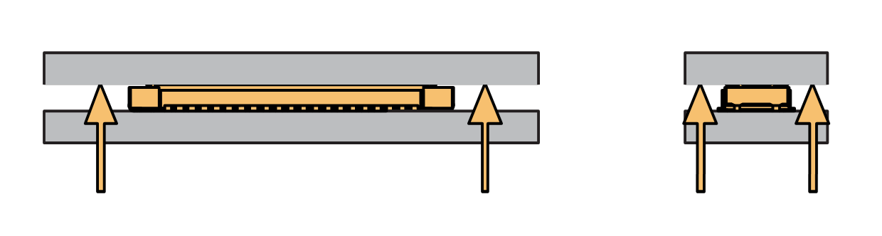 Figure 1: Correct way: Applying even forces to detach the header from the socket
- Avoid pulling out the header asymmetrically in the long-side direction.
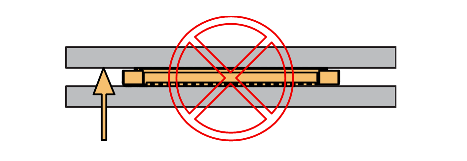 Figure 1: Wrong way: Applying uneven forces to detach the header from the socket
- The short-side of the connector can be pulled out asymmetrically, but apply the force vertically and avoid rotating the header.
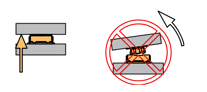 Figure 1: Wrong way: Do not rotate the header
- Avoid applying forces in a single corner.
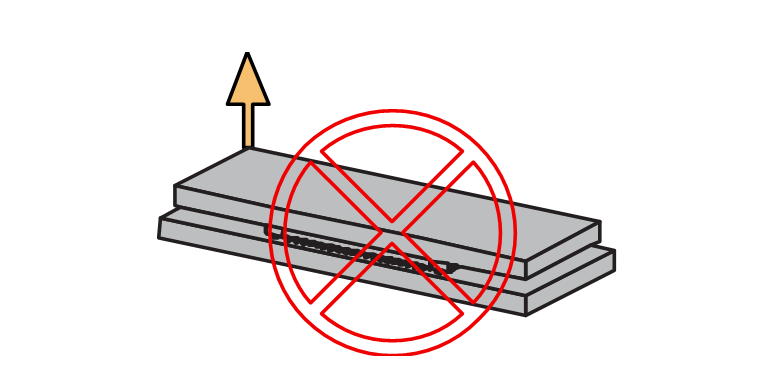 Figure 1: Wrong way: Do not apply force in a single corner of the header
WisBlock Module Installation
Assembling a WisBlock Module
WisBlock Core
Install the WisBlock Core module in the CPU slot on the RAK19001 Base Board, as indicated by the silkscreen. Follow carefully the procedure defined in attaching a WisConnector section in order to attach a Core module. Once attached, fix the module with one or more pieces of M1.2 x 3 mm screws depending on the WisBlock Core.
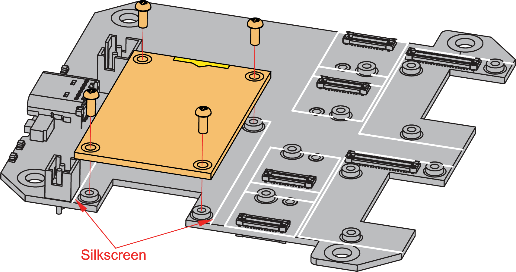 Figure 1: WisBlock Core silkscreen on the RAK19001 Base Board
WisBlock Sensor
A WisBlock Sensor module is designed to be installed in one of the six sensor slots on the RAK19001 Base Board. Each slot is clearly marked on the silkscreen. Follow carefully the procedure of the section, attaching a WisConnector, to attach a WisBlock Sensor module. Once attached, fix the module with an M1.2 x 3 mm screw.
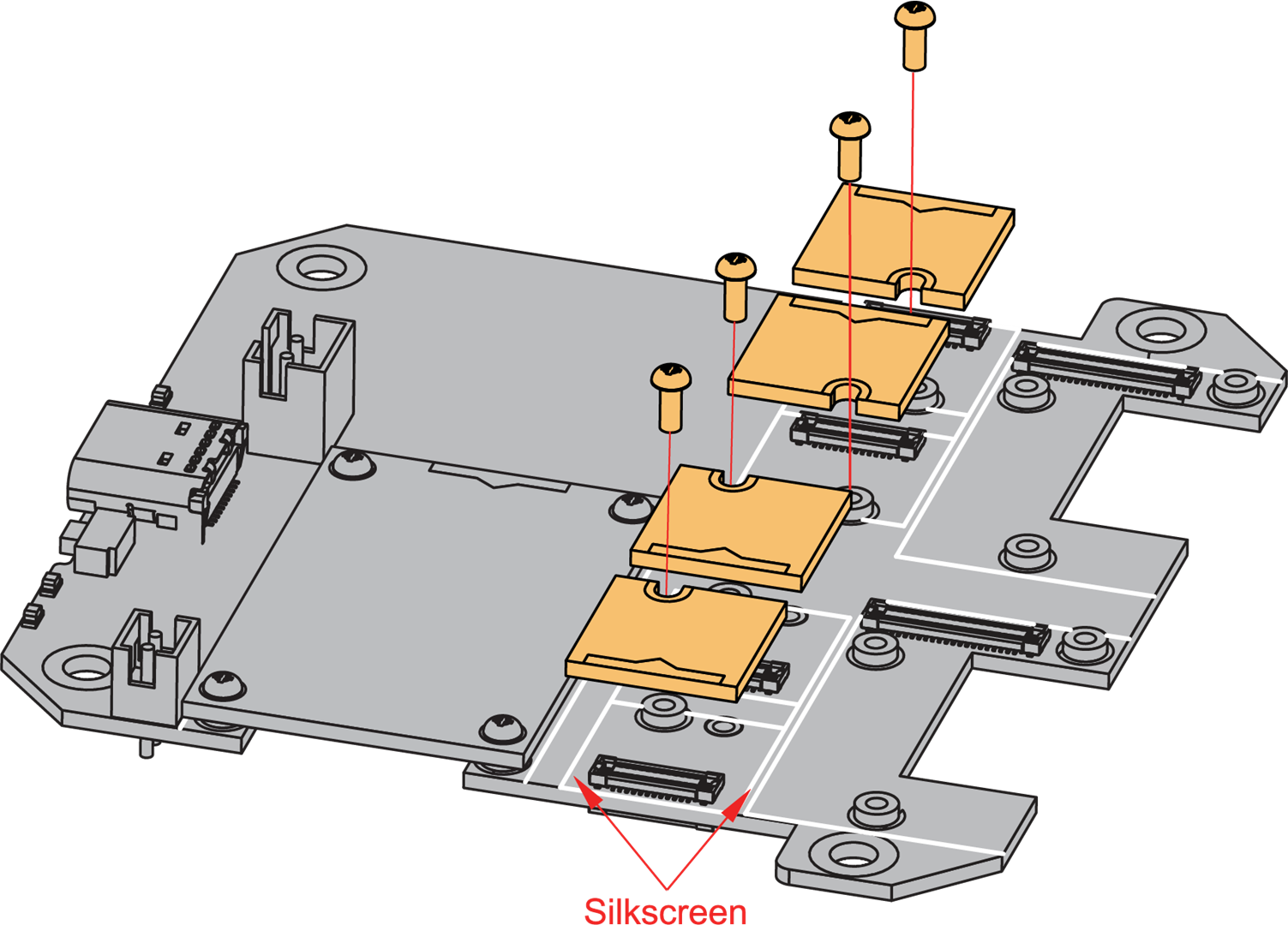 Figure 1: WisBlock Sensor silkscreen on the RAK19001 Base Board
WisBlock IO
A WisBlock I/O module is designed to be installed in one of the two I/O slots on the RAK19001 Base Board. Each slot is clearly marked on the silkscreen. Follow carefully the procedure of the section, attaching a WisConnector, to attach a WisBlock IO module. Once attached, fix the module with three pieces of M1.2 x 3 mm screws.
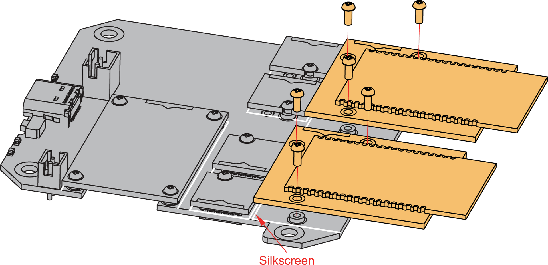 Figure 1: WisBlock IO silkscreen on the RAK19001 Base Board
Disassembling a WisBlock Module
- The procedure for removing any type of WisBlock module is the same. First, remove the screws.
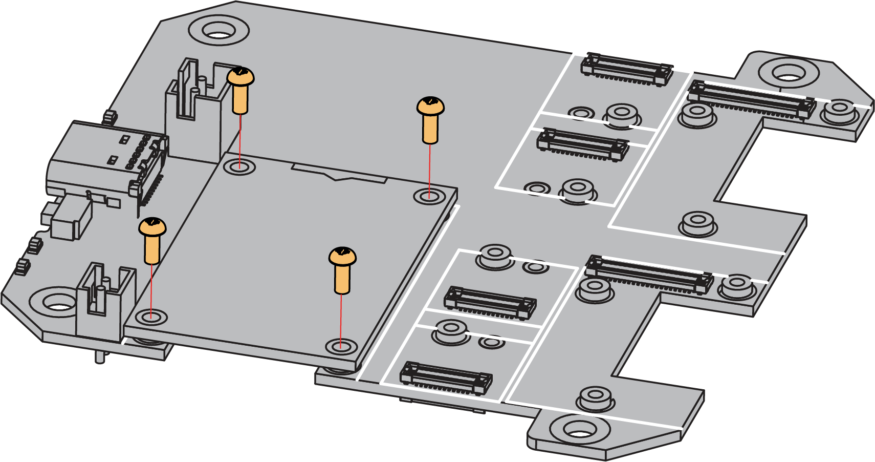 Figure 1: Removing screws from the WisBlock module
- Once the screws are removed, on the PCB of a WisBlock module, there is a silkscreen that shows the correct location where force can be applied. By applying even force under the marked area, the module can be detached from the Base Board.
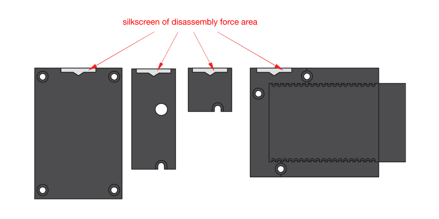 Figure 1: Detaching silkscreen on the WisBlock module
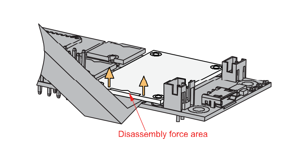 Figure 1: Applying even forces on the proper location of a WisBlock module to detach the module from the Base Board


