RAK19001 WisBlock Dual IO Base Board Quick Start Guide
This guide introduces the RAK19001 WisBlock Base Board and how to use it.
Prerequisite
What Do You Need?
Before going through each and every step on using the RAK19001 WisBlock Base Board, make sure to prepare the necessary items listed below:
Hardware
-
Your choice of WisBlock Core
-
Your choice of WisBlock Modules.
NOTEIt is highly recommended to also check the dedicated quick start guide that you can follow on various WisBlock Modules. Each quick start guide of these modules contains the detailed steps on how to open the example codes and upload them to the WisBlock Core.
-
Type-C USB cable for programming and debugging
Software
Based on the choice of the WisBlock Core, select a Development Environment:
Programming via Arduino IDE-
RAKwireless BSP support for Arduino
In Arduino IDE, once you installed the BSP, the examples for WisBlock Core will be automatically included on the list of examples.
Product Configuration
Overview
To give you a better understanding of how the WisBlock Base works, the block diagram RAK19001 is provided in this section.
Block Diagram
The block diagram shows the internal architecture and external interfaces of the RAK19001 board.
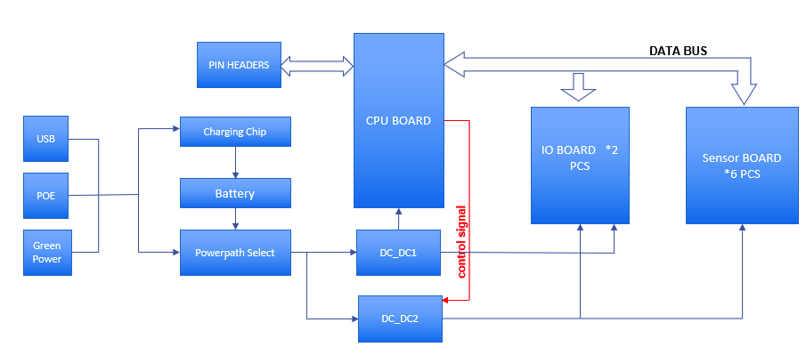 Figure 1: RAK19001 WisBlock Base block diagram
The MCU in the WisBlock Core module offers the I2C, UART, and SPI data buses to the sensor and IO modules. Through these buses, the MCU can control and retrieve data from the sensors. The RAK19001 WisBlock Base board connects all these modules.
The RAK19001 is designed to be powered by either rechargeable or non-rechargeable battery. The rechargeable battery it supports is Li-Ion and provides the necessary charger IC on-board. The charger circuitry can be connected to a wall outlet charger through the Type-C USB connector or via the solar panel connector.
A high-efficiency step-down converter with a low quiescent current is used for generating 3.3 V. This 3.3 V power supply drives the consumption of the WisBlock Core module and the sensor modules.
3V3_S is another 3.3 V power supply, it can be controlled by the MCU to disconnect the power to the sensor and interface modules during idle periods. 3V3_S is controlled by an IO2 pin on the WisBlock Core board.
- Set IO2=1, 3V3_S is on.
- Set IO2=0, 3V3_S is off.
Hardware Setup
RAK19001 WisBlock Base Board Installation Guide
The RAK19001 WisBlock Base Board provides standardized connectors for compatible WisBlock Core, Sensor, and I/O modules. For installation details, refer to RAK19001 WisBlock Dual IO Base Board Installation Guide.
Battery Selector
The RAK19001 supports both rechargeable and non-rechargeable batteries. You can also use this slide switch as a power on/off switch to disconnect the battery from the board.
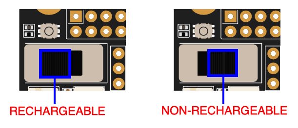 Figure 1: Battery selector switch
Non-Rechargeable Battery
Various non-rechargeable batteries are supported by the RAK19001 as long as it is in the voltage range of 3.3 to 5.5 V. The onboard connector used on the non-rechargeable battery is FWF20009-S02S22W1B. The matching connector housing is FHG20005-S02M2W1B, and the connector tin-plate pin is FT20004-F2H.
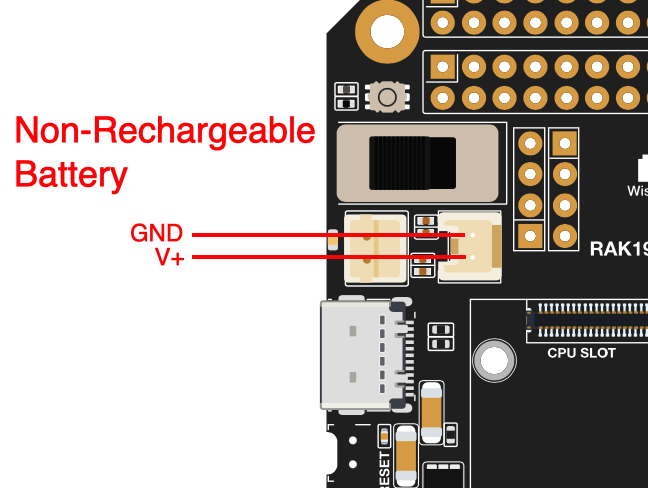 Figure 1: Non-Rechargeable battery connector pin
Rechargeable Battery
RAK19001 can be powered by a rechargeable Li-Ion/LiPo battery via the dedicated connectors. The matching connector for the rechargeable battery wires is a JST PHR-2 2 mm pitch female. A cable assembly for the rechargeable battery connector is also available for purchase in RAK store.
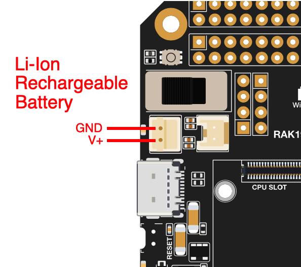 Figure 1: Rechargeable battery connector pin
- Battery can cause harm if not handled properly.
- Only 3.7-4.2 V Rechargeable LiPo batteries are supported. It is highly recommended not to use other types of batteries with the system unless you know what you are doing.
- On non-rechargeable batteries, the ideal range is 3.3 to 5.5 V.
- Make sure the battery wires, both rechargeable and non-rechargeable, match the polarity on the RAK19001 board. Not all batteries have the same wiring.
Solar Panel Connection
The battery can be recharged, as well, via a small Solar Panel. The matching connector for the solar panel wires is an JST ZHR-2 1.5 mm pitch female. A cable assembly for the solar panel connector is also available for purchase in RAK store.
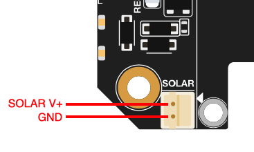 Figure 1: Solar panel connector V+ and GND
- Only 5 V solar panels are supported. Do not use 12 V solar panels. It will destroy the charging unit and eventually other electronic parts.
- The GND pin of the Solar Panel Connector is located on edge of the board. Make sure the solar panel wires match the polarity on the RAK19001 board.
Software Setup
For software configuration, refer to RAK19001 WisBlock Dual IO Base Board Software Configuration.


