RAK3172 Evaluation Board Datasheet
Overview
Description
The RAK3172-E is a WisDuo evaluation board for the RAK3172 module, using an STM32WLE5CCU6 SoC chip. It is based on the RAK3372 WisBlock Core, compatible with the RAK19007 base board. It provides easy access to the important pins of the RAK3172 module, simplifying development and testing. It also allows connection of other modules to the base board slots, enabling the building of complete IoT projects with integrated connectors for battery and solar panel, plus an onboard charging circuit.
This module complies with LoRaWAN 1.0.3 specifications (Classes A, B, and C). It also supports LoRa point-to-point (P2P) communication, facilitating the quick implementation of customized long-range LoRa networks.
Features
- Based on STM32WLE5CCU6
- LoRaWAN 1.0.3 specification compliant
- Supported bands: EU433, CN470, IN865, EU868, AU915, US915, KR920, RU864, and AS923-1/2/3/4
- LoRaWAN Activation by OTAA/ABP
- LoRa Point-to-Point (P2P) communication
- Custom firmware using Arduino via RUI3 API
- Easy to use AT command set via UART interface
- Long-range - greater than 15 km with optimized antenna
- ARM Cortex-M4 32-bit
- 256 kbytes flash memory with ECC
- 64 kbytes RAM
- Supply Voltage: 5 V via USB or 3.7-4.2 V using Li-Ion Battery
- Temperature Range: -20° C ~ 70° C
Specifications
This section covers the hardware and software specifications for the RAK3172 Evaluation Board. It includes the interfaces, operating parameters, and a link to the board's latest firmware.
Overview
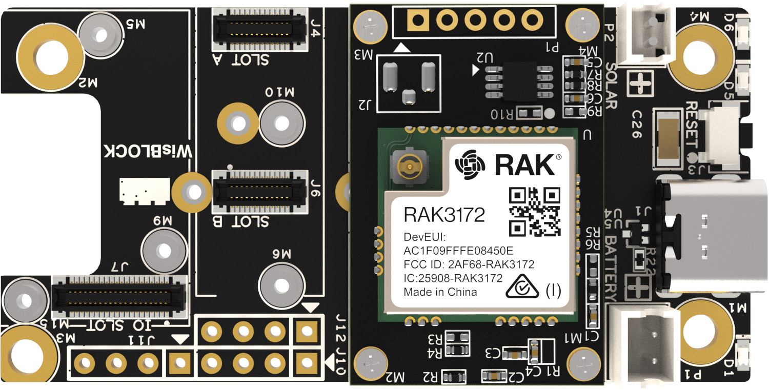 Figure 1: RAK3172 Evaluation Board Overview
Hardware
The hardware specification is categorized into six parts. It discusses the interfacing, pinouts, and their corresponding functions and diagrams. It also covers the electrical, mechanical, and environmental parameters, including tabular data of the functionalities and standard values of the RAK3172 Evaluation Board.
Interfaces
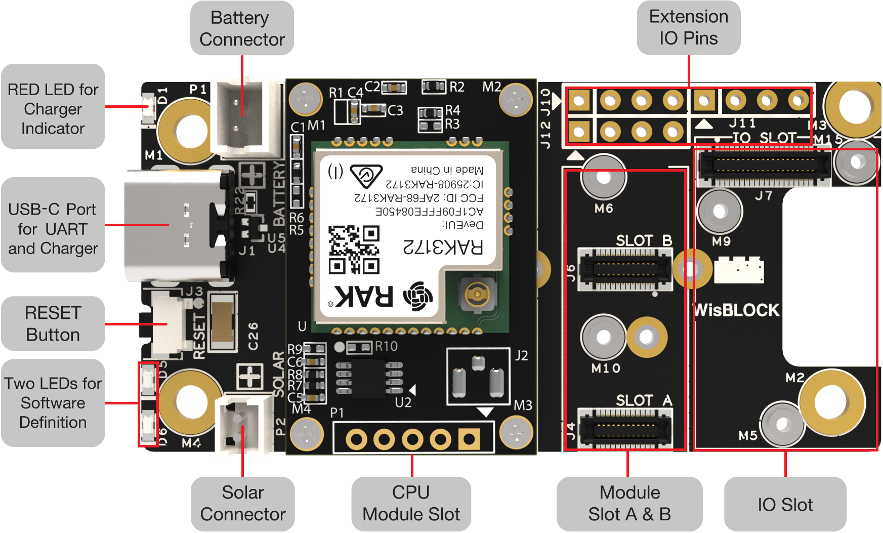 Figure 1: RAK3172 Evaluation Board Interfaces
 Figure 1: Parts of RAK3372 Module
RF Interface
The RF Antenna of the RAK3172 Evaluation Board is connected to a standard iPEX antenna connector.
 Figure 1: RAK3172 LoRa antenna
Make sure to install the LoRa antenna first before powering the RAK3172 Evaluation Board. Failure to do so can damage the board.
Type-C USB port
The Type-C USB connector is compliant with the USB 2.0 specification. This USB interface directly communicates with the connected WisBlock Core module. It is also used as a charging input port for the battery. Here are some of the advantages of the Type-C USB connector:
- Smaller and reversible connector shape
- Port can be input or output
- Fast battery charging
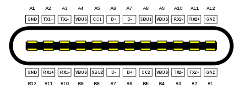 Figure 1: RAK3172 USB-C connector
Battery Connector
The RAK3172 Evaluation Board can be powered by a battery via the P1 connector. The battery is not included in the packaging.
Use Figure 6 as a guide to connect the battery. The pin highlighted in the yellow box with the triangle silkscreen mark indicates pin 1 (GND).
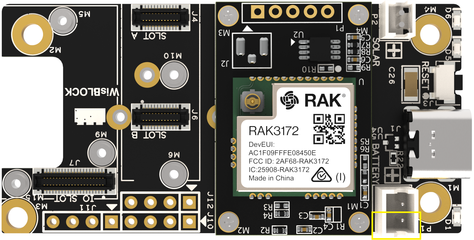 Figure 1: RAK3172 EVB battery connector
The pin definition of the RAK3172 Evaluation Board Li-Ion battery connector is shown in the table below. The matching connector for the battery wires is a JST PHR-2 2 mm pitch female.
P1 Battery Connector| Pin | Pin Name | Description |
|---|---|---|
| 1 | GND | Ground |
| 2 | VBAT | Positive + pin of the battery |
The full specification of RAK3172 Evaluation Board battery is shown in the table below.
| No. | Item | Specification |
|---|---|---|
| 1 | Charge Cut-off Voltage | 4.2 V |
| 2 | Nominal Voltage | 3.7 V |
| 3 | Discharge Cut-off Voltage | 2.75 V |
| 4 | Typical Capacity | 2650 mAh |
| 5 | Max Discharge Current | 0.5 C at 25 ℃ to 45 ℃ |
| 6 | PH Connector | 2.0 mm pitch |
| 7 | Cable Length | 110.0±3.0 mm |
| 8 | Cable Color | Red: VBAT, Black: GND |
The voltage of the Li-Ion battery must not exceed 4.3 V. When connecting the battery make sure the polarity is correct. Not all connectors are wired the same.
Solar Panel Connector
A 5 V solar panel can be connected to the board via the P2 connector to charge the battery. The solar panel is not included in the RAK3172 Evaluation Board packaging. Use Figure 7 as a guide to connect the solar panel. The pin highlighted in the yellow box with triangle silkscreen marking indicates pin 1 (5 V solar panel positive).
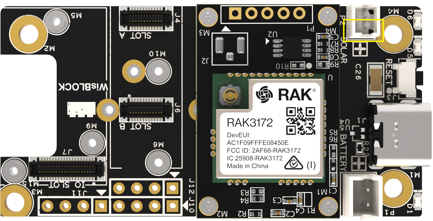 Figure 1: RAK3172 EVB solar connector
The pin definition of the RAK3172 Evaluation Board solar panel connector is shown in the table below. The matching connector for the solar panel wires is an JST ZHR-2 1.5 mm pitch female.
P2 Solar Panel connector| Pin | Pin Name | Description |
|---|---|---|
| 1 | C0NN_5V | Positive + pin of solar panel |
| 2 | GND | GND |
The full specification of the Solar Panel for the RAK3172 Evaluation Board is shown in the table below.
| No. | Item | Specification |
|---|---|---|
| 1 | Nominal Voltage | 5 V |
| 2 | Typical Current | 80 mA |
| 3 | Size | Length: 60 mm, Width: 60 mm, Height: 2 mm |
| 4 | Connector | 1.5 mm pitch |
| 5 | Cable Color | Red: C0NN_5V, Black: GND |
The output of the solar panel must not exceed 5.5 V. Otherwise, it may cause permanent damage to the board.
LEDs
- 🔴 Red LED - connected to the charger chip to indicate the charger status. When the battery is charging, the red LED is on. When the battery is full, this LED is dimmed or off.
- 🟢 Green LED - connected to the MCU module, can be controlled in code by the user.
- 🔵 Blue LED - connected to the MCU module, can be controlled in code by the user.
RESET Button
The reset push button is connected to the NRST pin of the RAK3172. When pushed, it resets the MCU.
Pin Definition
The following tables below show the pin definitions of the RAK3172 Evaluation Board:
J10, J11, J12 2.54 mm Header
J10
| Pin | Pin Name | Description |
|---|---|---|
| 1 | BOOT | MCU BOOT pin |
| 2 | GND | Ground pin |
| 3 | TX1 | UART1 TX pin |
| 4 | RX1 | UART1 RX pin |
J11
| Pin | Pin Name | Description |
|---|---|---|
| 1 | AIN1 | ADC input signal |
| 2 | IO1 | General purpose IO |
| 3 | IO2 | General purpose IO |
| 4 | VBAT | Battery voltage |
J12
| Pin | Pin Name | Description |
|---|---|---|
| 1 | VDD | 3.3 V |
| 2 | GND | Ground pin |
| 3 | SCL | I2C1 clock |
| 4 | SDA | I2C1 data |
RF Characteristics
The RAK3172 supports two frequency variations: RAK3172(L) for low radio frequencies and RAK3172(H) for high radio frequencies.
Operating Frequencies
| Module | Region | Frequency |
|---|---|---|
| RAK3172(L) | Europe | EU433 |
| China | CN470 | |
| RAK3172(H) | Europe | EU868 |
| North America | US915 | |
| Australia | AU915 | |
| Korea | KR920 | |
| Asia | AS923-1/2/3/4 | |
| India | IN865 | |
| Russia | RU864 |
Electrical Characteristics
Operating Voltage
Power is supplied to the RAK3172 Evaluation Board via USB (5 V) or a Li-Ion battery.
The LDO regulator can operate on the following voltage range:
| Feature | Minimum | Maximum | Unit |
|---|---|---|---|
| Vin | 1.8 | 6.5 | Volts (V) |
Mechanical Characteristics
Module Dimensions
 Figure 1: RAK3172 Physical Dimension
Environmental Characteristics
Operating Temperature
| Feature | Minimum | Typical | Maximum | Unit |
|---|---|---|---|---|
| Operating Temperature | -35 | 25 | 70 | °C |
Software
Download the latest firmware for the RAK3172 WisDuo evaluation board provided below. The RAK3172(L) and RAK3172(H) use the same firmware; it will automatically detect the module variant.
The bin file contains the application code only and you need the RAK DFU Tool to upload this file to the module.
The hex file contains both the bootloader and the application code. You need to use STM32CubeProgrammer to upload this.
Uploading the **.hex** file via STM32CubeProgrammer will erase all configured data on the device.
RAK3172 uses UART2's serial pins to upload the latest firmware.
RAK3172 should automatically go to BOOT mode when the firmware is being uploaded via RAK DFU Tool or WisToolBox.
If BOOT mode is not initiated, you can manually send AT+BOOT command to start bootloader mode.
Schematic Diagram
 Figure 1: RAK3172 Evaluation Board Schematic Diagram
Firmware/OS
| Model | Version | Source |
|---|---|---|
| RAK3172 | RUI3 (default baudrate = 115200) | Download |
| RAK3172 | RUI3 (default baudrate = 115200) | Download |
| RAK3172 | DEPRECATED V1.0.4 (default baudrate = 9600) | Download |
There are RAK3172 devices loaded with old firmware versions which are not based on RUI3 (RAKwireless Unified Interface V3). These devices have v1.0.4 and below.
If the host microcontroller code is based on this old firmware, we have a RAK3172 AT Command migration guide that explain in detail the few differences between the two AT commands set.
Certification
For CE and FCC certifications we provide an AT command guide.
You can find it in our RUI3 documentation or get it from our Download Center.


