RAK3172-SiP WisDuo LPWAN SiP as a LoRa/LoRaWAN Modem via AT Commands
This guide shows how to configure the RAK3172-SiP as a LoRa/LoRaWAN modem using AT commands. It covers device registration and configuration with The Things Stack (TTN) and ChirpStack, supporting both OTAA and ABP activation.
Before configuring the RAK3172-SiP using AT commands, connect the module to your computer using a USB-to-UART TTL adapter. For detailed instructions, refer to the RAK3172-SiP Quick Start Guide.
Choose your LoRaWAN network server to get started:
- Connect to The Things Network (TTN): Resgister device on TTN and configure the RAK3172-SiP using AT commands.
- Connect to ChirpStack: Resgister device on ChirpStack and configure the RAK3172-SiP using AT commands.
The screenshots are based on the RAK4630, but the same procedure applies to the RAK3172-SiP.
Connect to TTN
The Things Stack is an open-source LoRaWAN Network Server for managing LoRaWAN devices and applications across public and private networks. It is maintained by The Things Industries.
This section explains how to set up LoRaWAN communication with The Things Stack (TTN). It covers registering a LoRaWAN gateway on TTN and configuring the RAK3172-SiP for OTAA or ABP activation using AT commands.
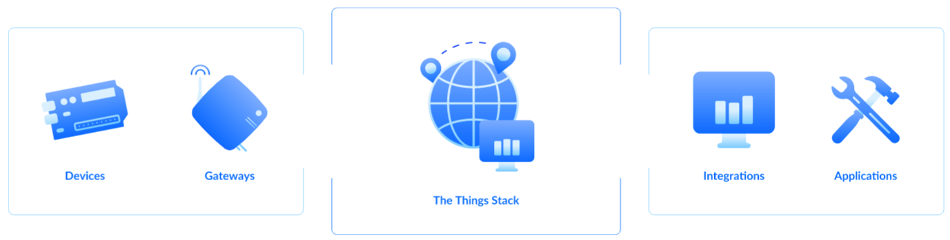 Figure 1: The Things Stack
Register the LoRaWAN Gateway on TTN
Choose the appropriate guide below to register and connect your RAK Gateway to The Things Stack (TTN v3):
- How to Register a RAK Gateway in TTN V3
- How to Connect RAK Gateways to TTN v3 via UDP
- How to Connect RAK Gateways to TTN v3 Using Basics™ Station (LNS)
- How to Auto-Connect RAK Gateway to TTN (EU1) in Packet Forwarder Mode
- How to Connect RAK Gateways to TTN v3 Using Basics™ Station (CUPS)
Register the RAK3172-SiP on TTN
Step 1: Create a TTN Application
-
Log in to The Things Stack using the account and cluster where your gateway is registered.
-
Once logged in, click **Create application **to create a new application.
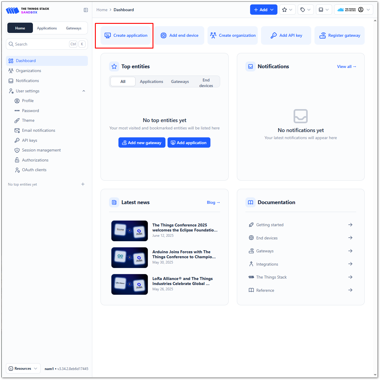 Figure 1: The Things Stack Platform
- To register an application, enter the required details and necessary information about your application, then click Create application.
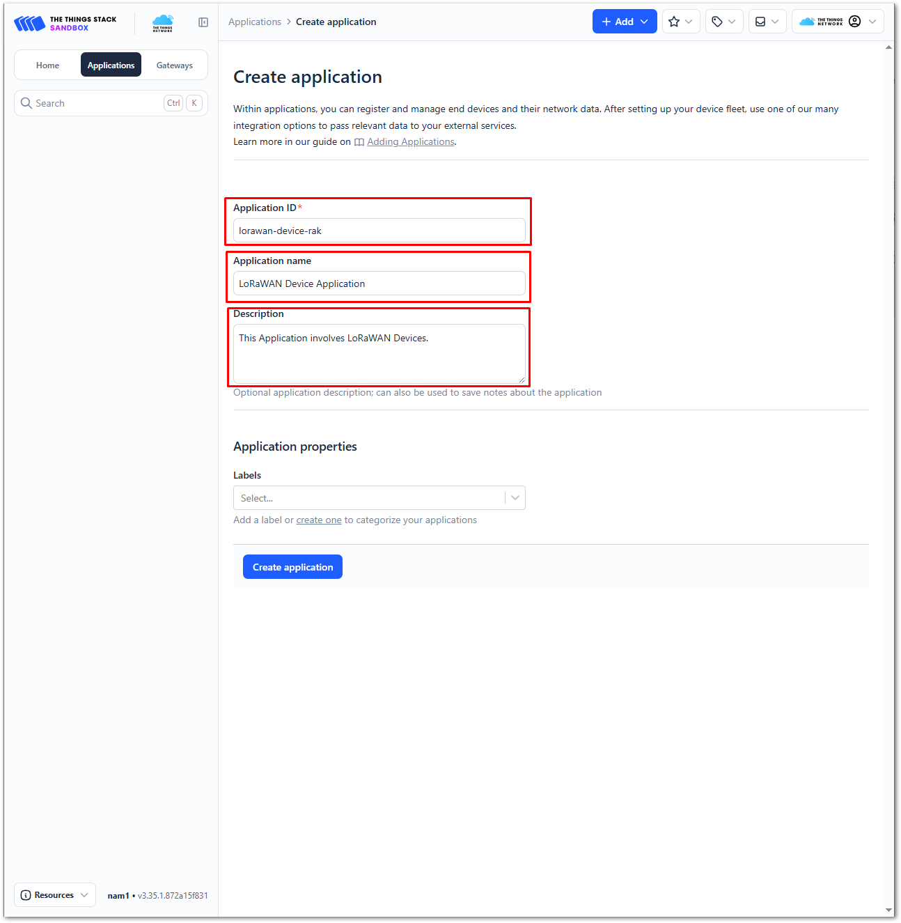 Figure 1: Details of the TTN application
- If you have no error in the previous step, you should now be on the application console page. The next step is to add end-devices to your TTN application.
Step 2: Register an End Device
Each LoRaWAN end device must be registered and activated using either Over-The-Air Activation (OTAA) or Activation By Personalization (ABP). Follow the steps below to register the module on TTN. Some configuration steps and credentials may differ depending on the selected activation method.
- Go to your application console to register a device. To start adding an OTAA end-device, click + Register end device.
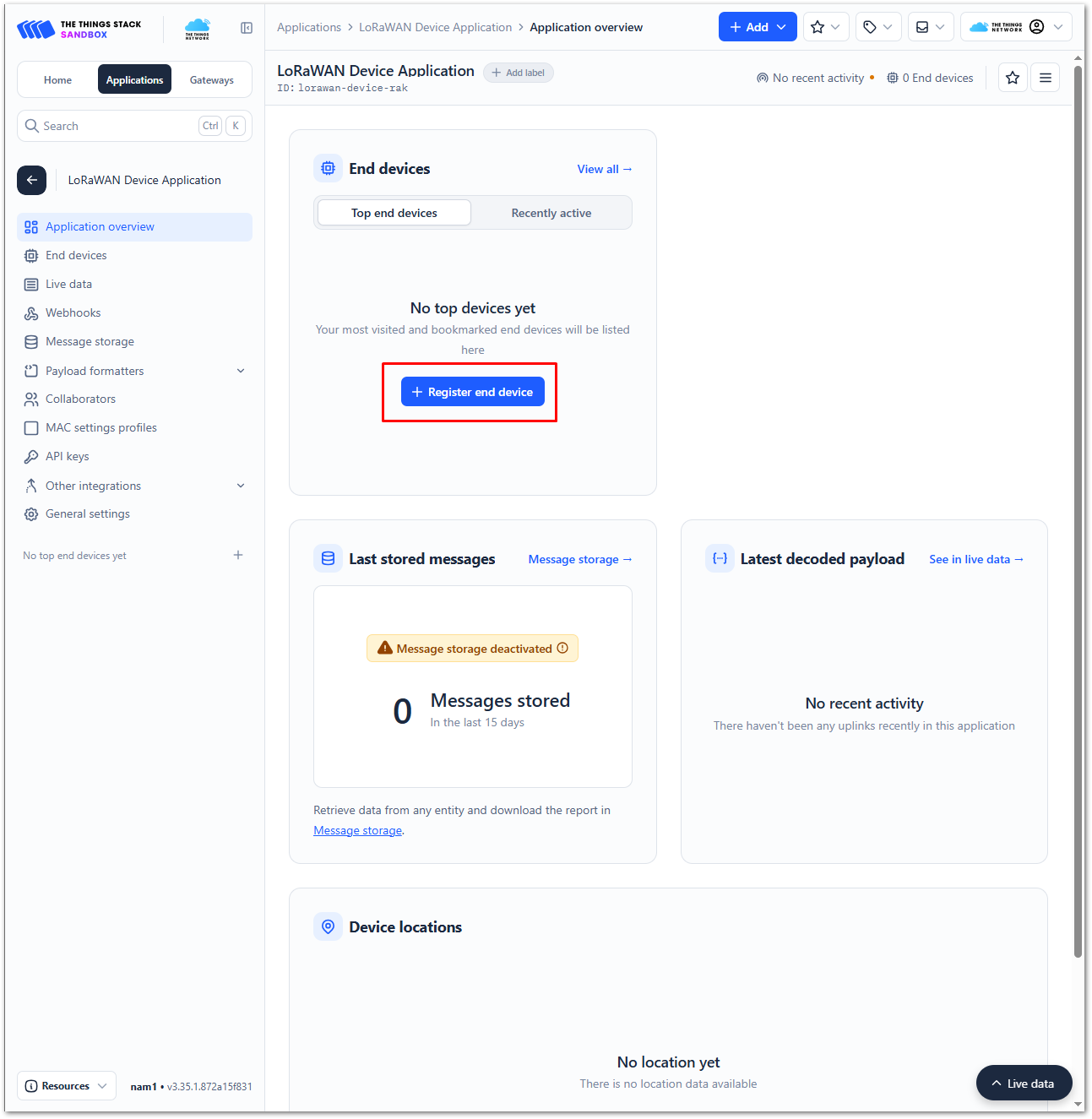 Figure 1: Register end device
- To register the board, select Enter end device specifics manually.
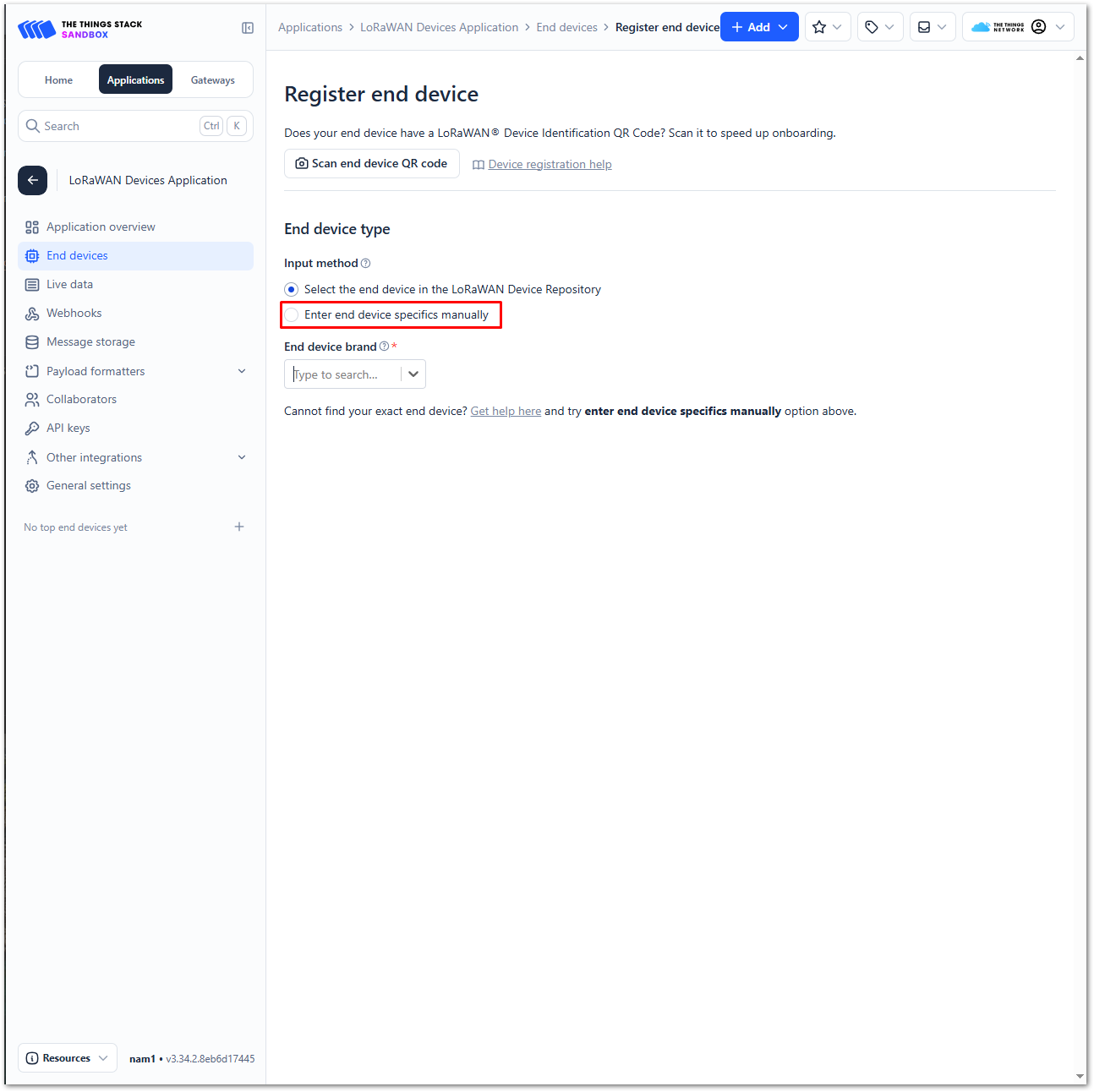 Figure 1: Enter end device specifics manually
- Set up the appropriate Frequency plan, compatible LoRaWAN version, and Regional Parameters version supported by your device. For OTAA activation, set the JoinEUI to all zeros. This step is not required for ABP activation.
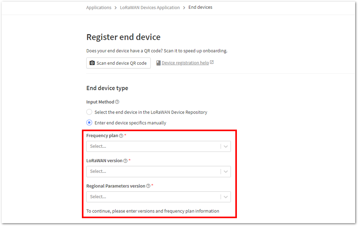 Figure 1: Setting up for your device
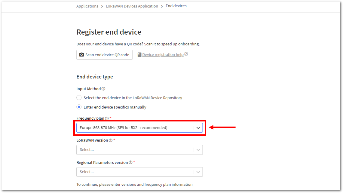 Figure 1: Setting the Frequency plan
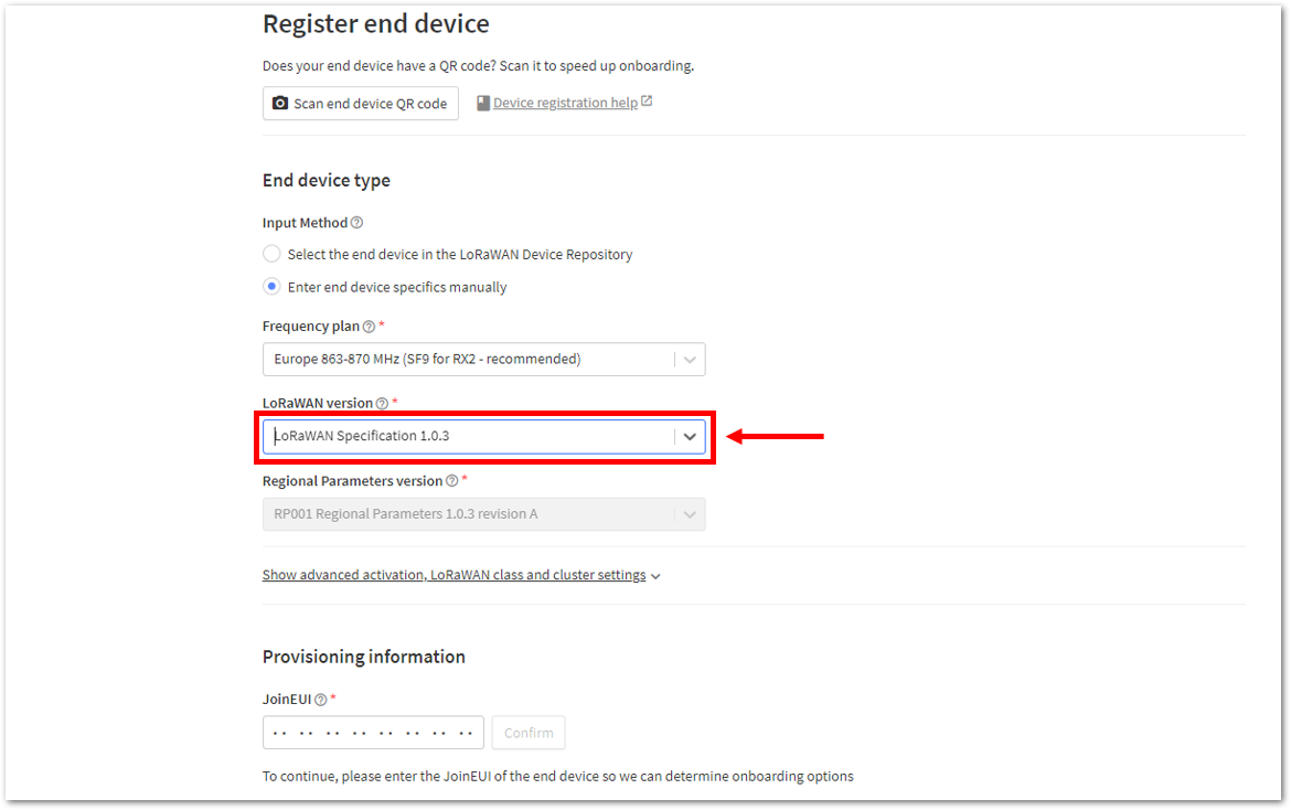 Figure 1: Setting the LoRaWAN version
 Figure 1: Setting the JoinEUI
- Click Show advanced activation, LoRaWAN class and cluster settings. Select the activation method supported by your device and set Additional LoRaWAN class capabilities to Class A only.
- OTAA: Select Over the air activation (OTAA). In the JoinEUI field, enter all zeroes to allow the DevEUI to be configured, then click Confirm.
- ABP: Select Activation by personalization (ABP).
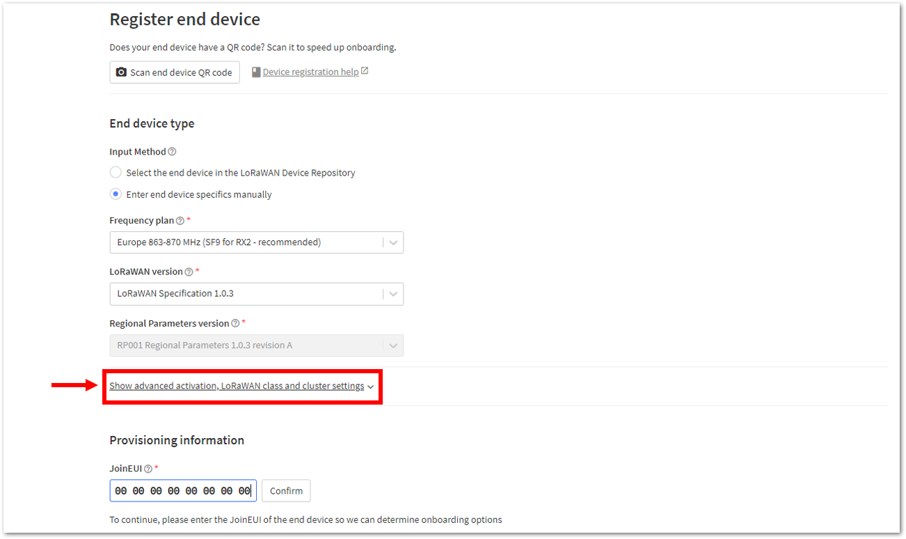 Figure 1: Setting up for your device
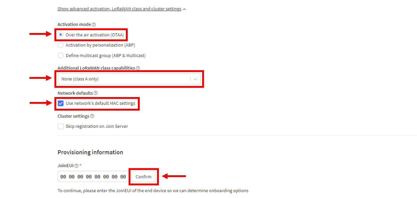 Figure 1: Configuring OTAA activation settings
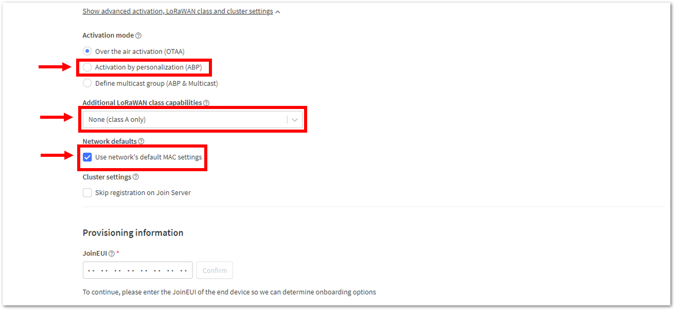 Figure 1: Configuring ABP activation settings
- Enter the DevEUI credentials of your device into the DevEUI portion. This will automatically generate the specific End device ID of your board. Then generate the credentials required by the selected activation method:
- OTAA: Generate the AppKey, then click Register end device.
- ABP: Generate the Device address, AppSKey, and NwkSKey.
- The DevEUI is unique to each RAK device. Depending on the activation mode, the following credentials are hidden in this section and must be generated for your specific device and application:
- ABP: Device address, AppSKey, and NwkSKey.
- OTAA: AppEUI and AppKey.
- For OTAA, the AppEUI is the same as the JoinEUI.
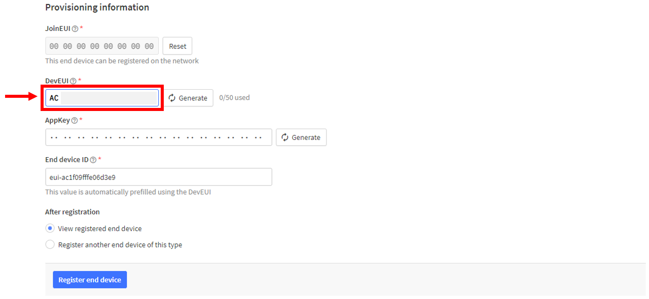 Figure 1: Generating OTAA credentials
 Figure 1: Generating ABP credentials
- Finally, click Register end device.
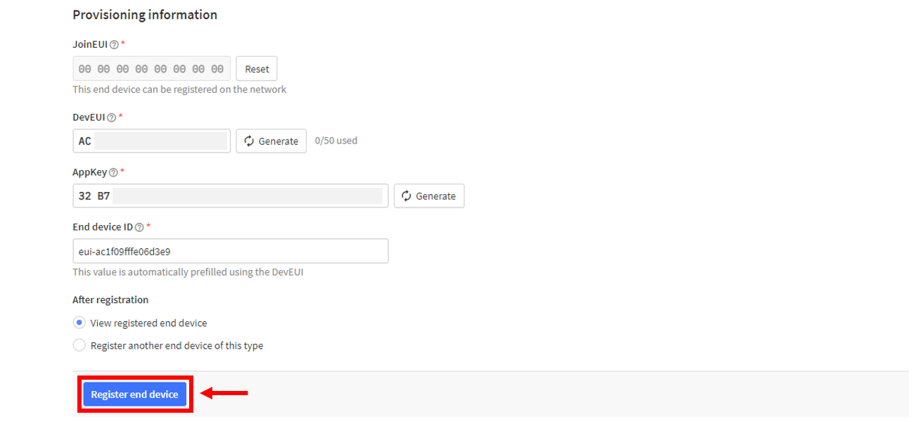 Figure 1: Register end device
- You should now be able to see the device on the TTN console after you fully register your device
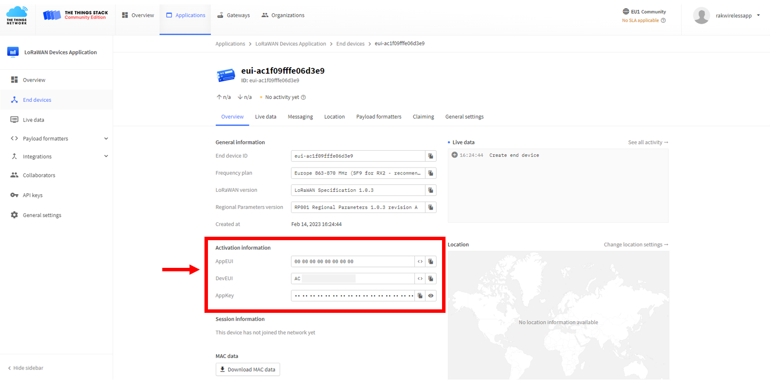 Figure 1: OTAA device successfully registered to TTN
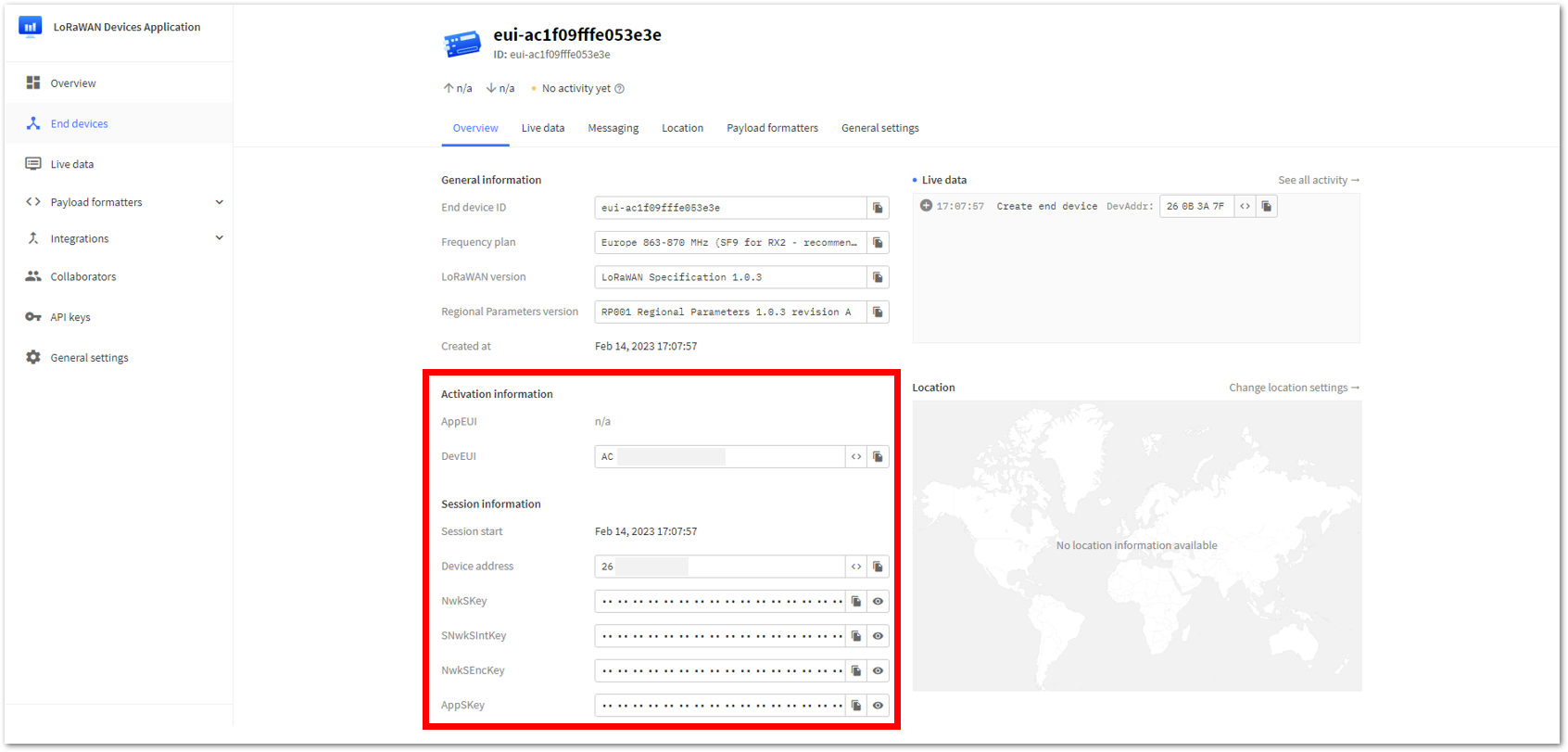 Figure 1: ABP device registered on TTN
After registering the device on TTN, choose the configuration method that matches your activation mode.
OTAA Configuration for TTN
The module can be configured using WisToolBox for OTAA setup. WisToolBox is a software tool designed to support the RAK end devices. It automatically detects the module once connected to the PC. The following section outlines the available WisToolBox UI options and steps for configuring OTAA:
OTAA Configuration for TTN via WisToolBox UI
The module must have the correct OTAA credentials to connect to TTN. This can be done using WisToolBox UI. Below are the steps on setting up your RAK module using WisToolBox.
- Open the WisToolBox application.
- Click the CONNECT DEVICE button to launch the WisToolBox dashboard.
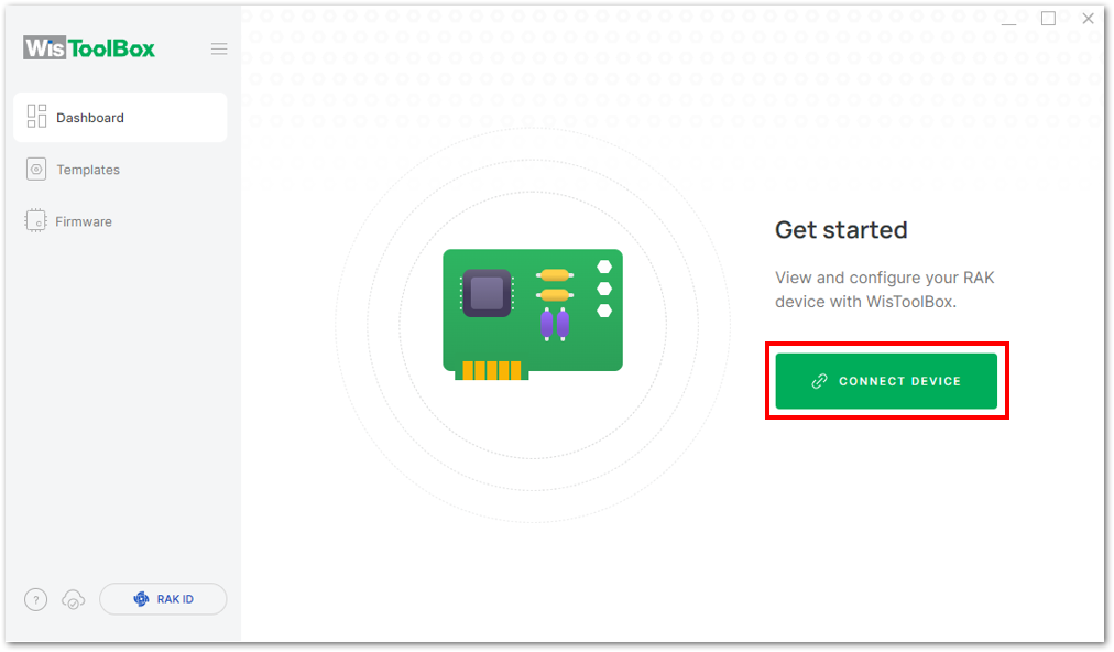 Figure 1: CONNECT DEVICE
- Then select your target port where your devices is connected. Once recognized, click CONNECT.
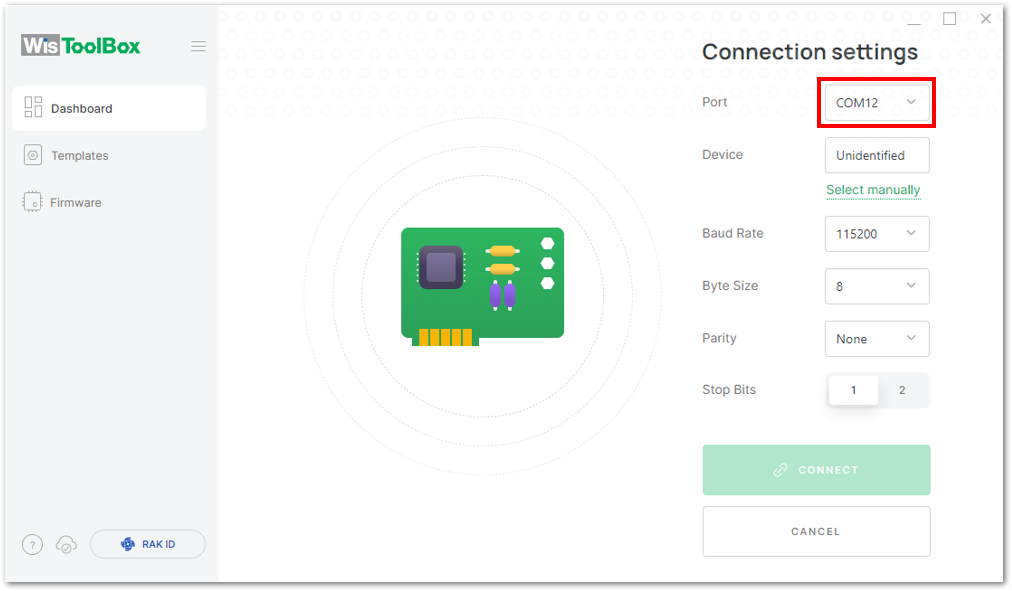 Figure 1: Setting up your device
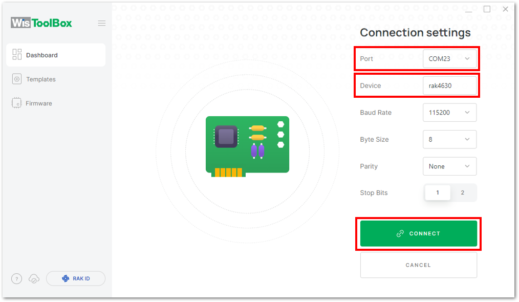 Figure 1: Setting up your device
- Once done, the device will appear in the dashboard then select it.
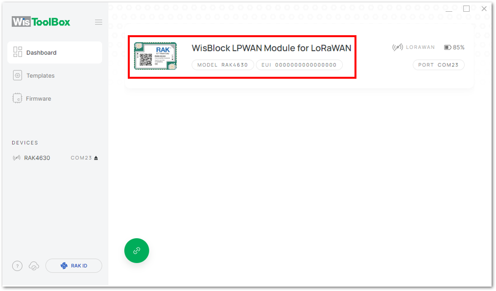 Figure 1: Device seen from WisToolBox dashboard
- Next, click on PARAMETERS to configure your module.
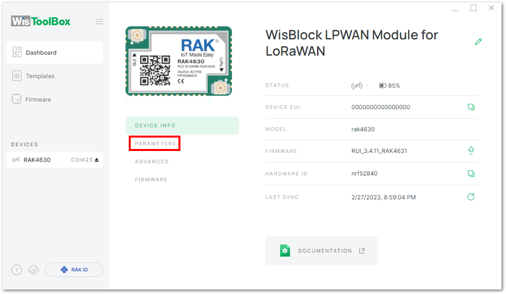 Figure 1: Setting up your device
-
Click on Global settings to set the network mode to LoRaWAN and the join mode to OTAA. Ensure that the active region is set to EU868 for this configuration. If you intend to operate in other regional bands, you can select the appropriate active region based on your location.
-
LoRa network mode: LoRaWAN
-
LoRaWAN join mode: OTAA
-
LoRaWAN region: EU868
-
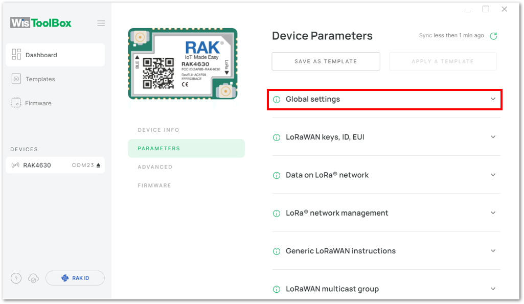 Figure 1: Global settings
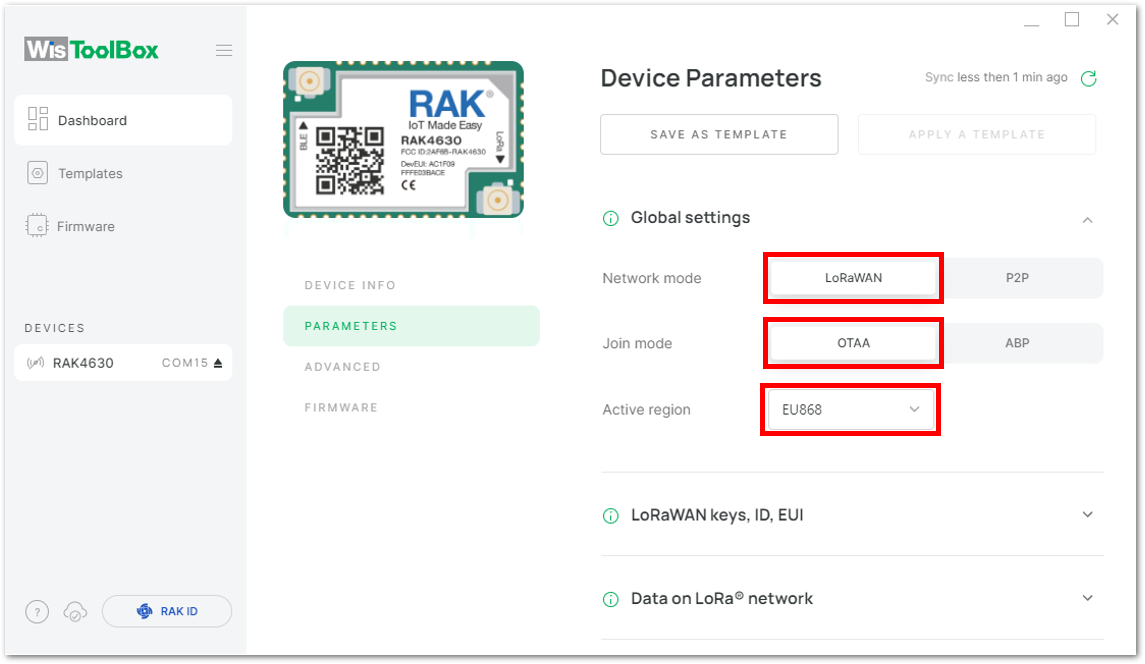 Figure 1: Global settings
- Configure the Application EUI (AppEUI), Application key (AppKey) and Device EUI (DevEUI).
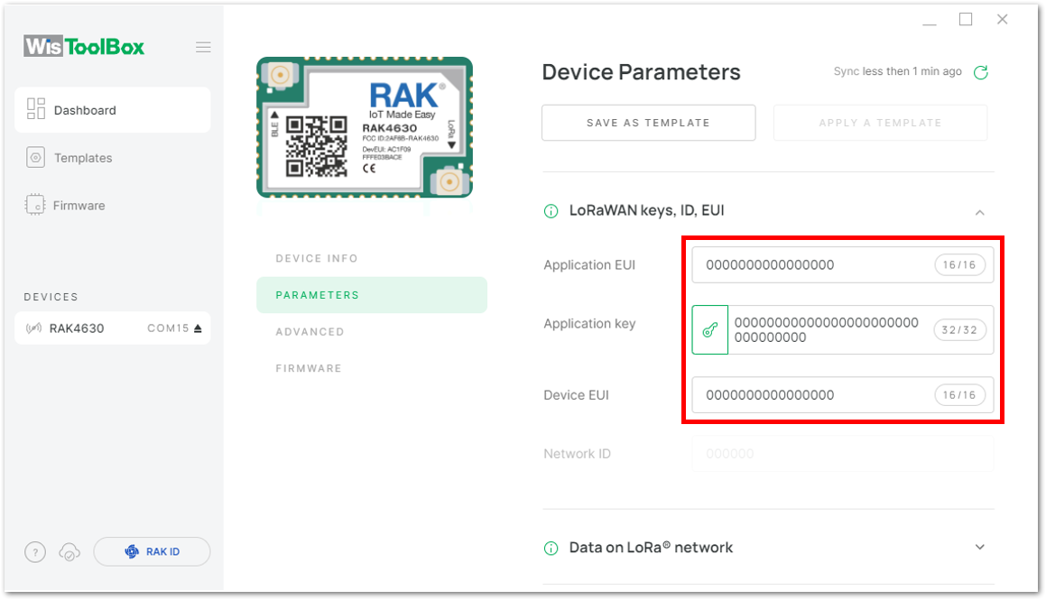 Figure 1: Setting up your device
- Return to the console where your device was previously created, copy the AppEUI, AppKey, and DevEUI to the corresponding fields in WisToolBox dashboard, then click APPLY COMMAND to apply the configuration.
The AppEUI, DevEUI, and AppKey are hidden in this section as these are unique from a specific device.
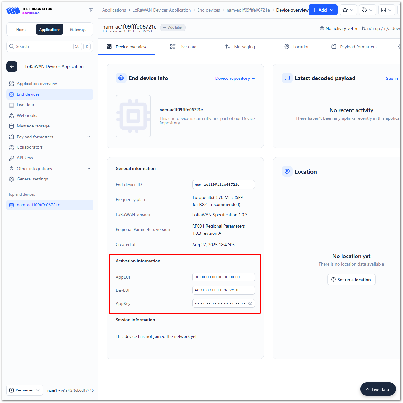 Figure 1: Your created OTAA device from your console
- For Application EUI (AppEUI)
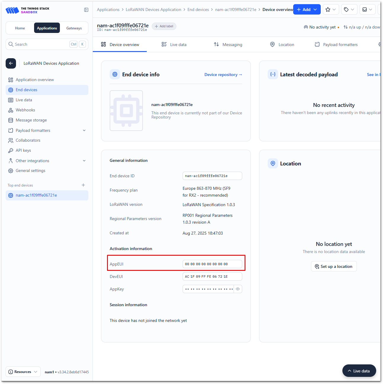 Figure 1: Copying the AppEUI credential from TTN to WisToolBox
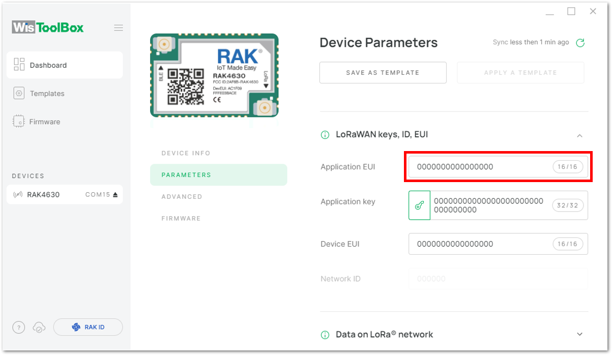 Figure 1: Copying the AppEUI credential from TTN to WisToolBox
- For Application key (AppKey)
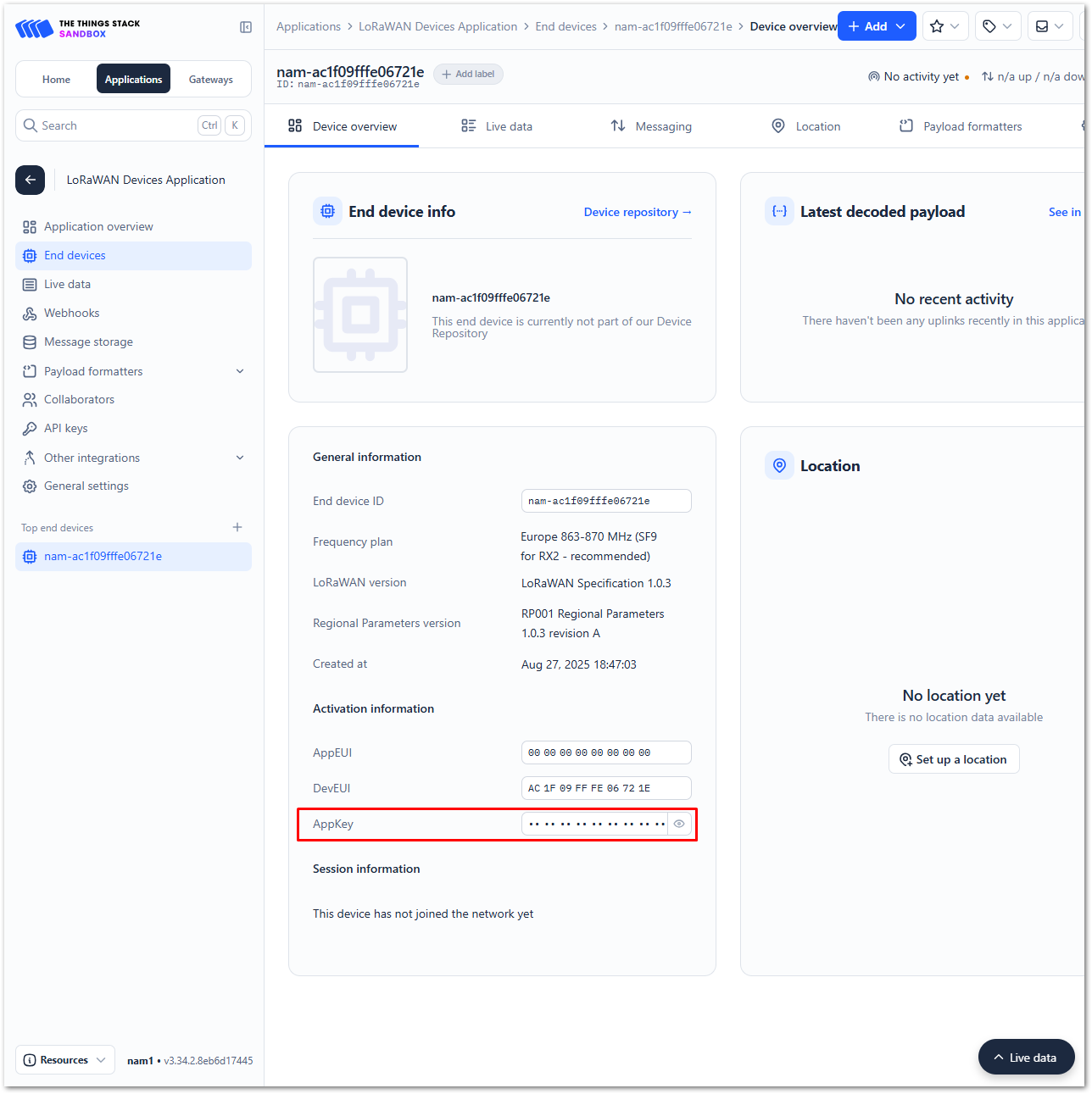 Figure 1: Copying the AppKey credential from TTN to WisToolBox
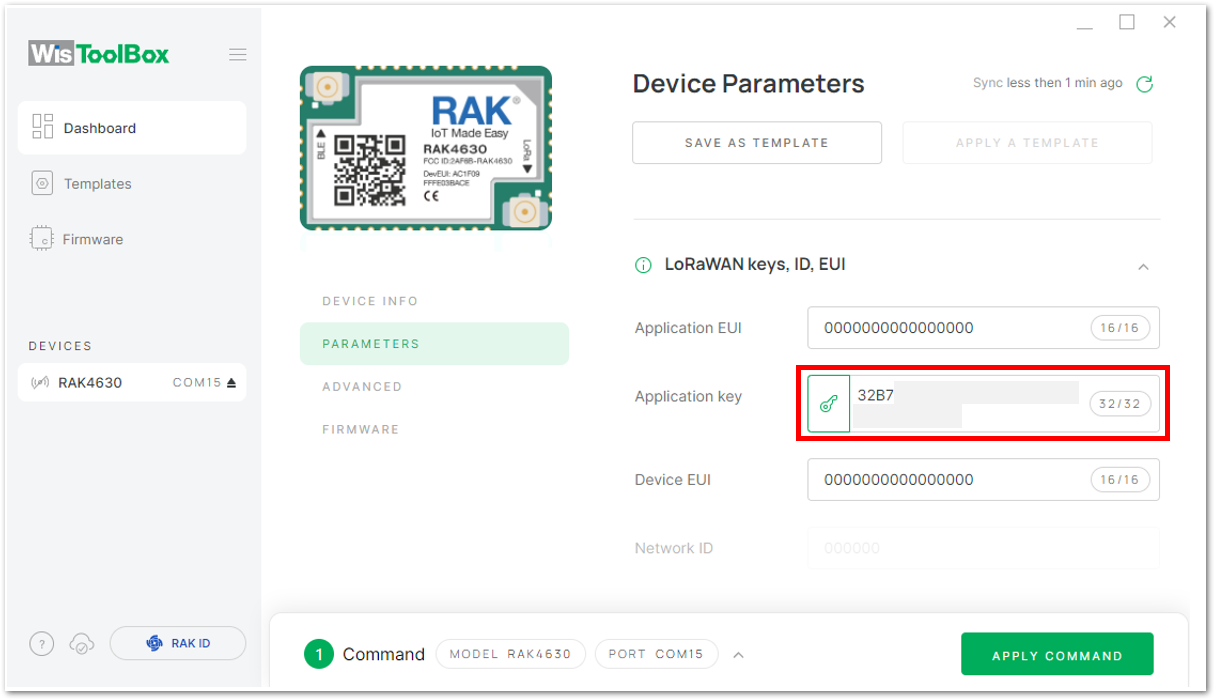 Figure 1: Copying the AppKey credential from TTN to WisToolBox
- For Device EUI (DevEUI)
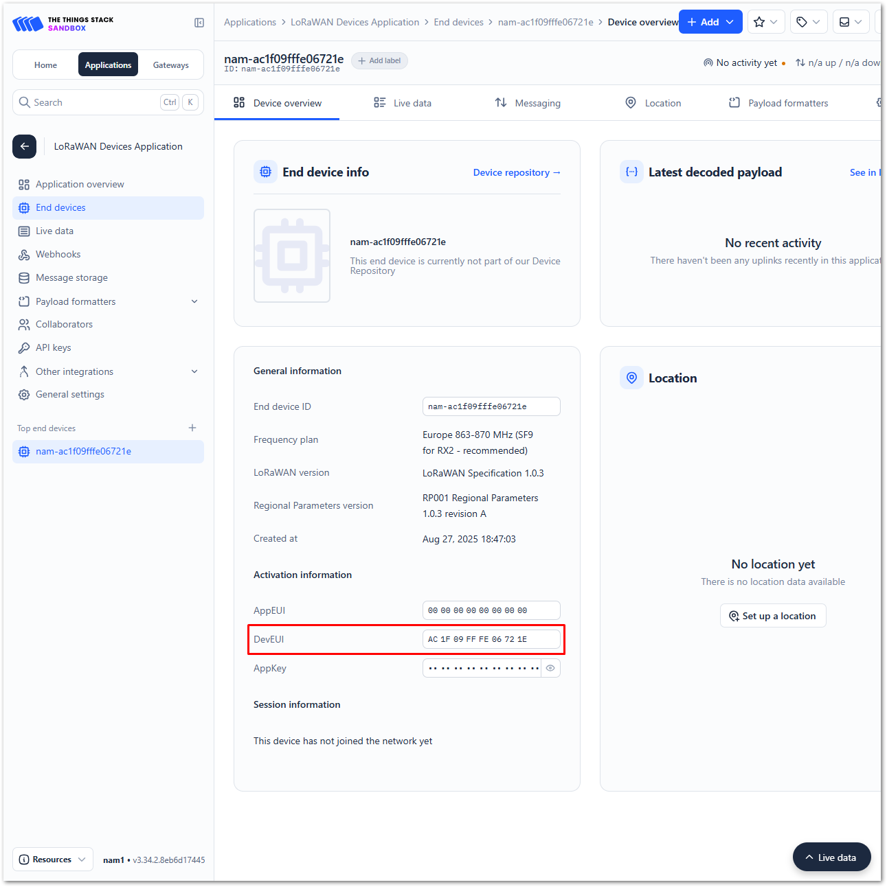 Figure 1: Copying the DevEUI credential from TTN to WisToolBox
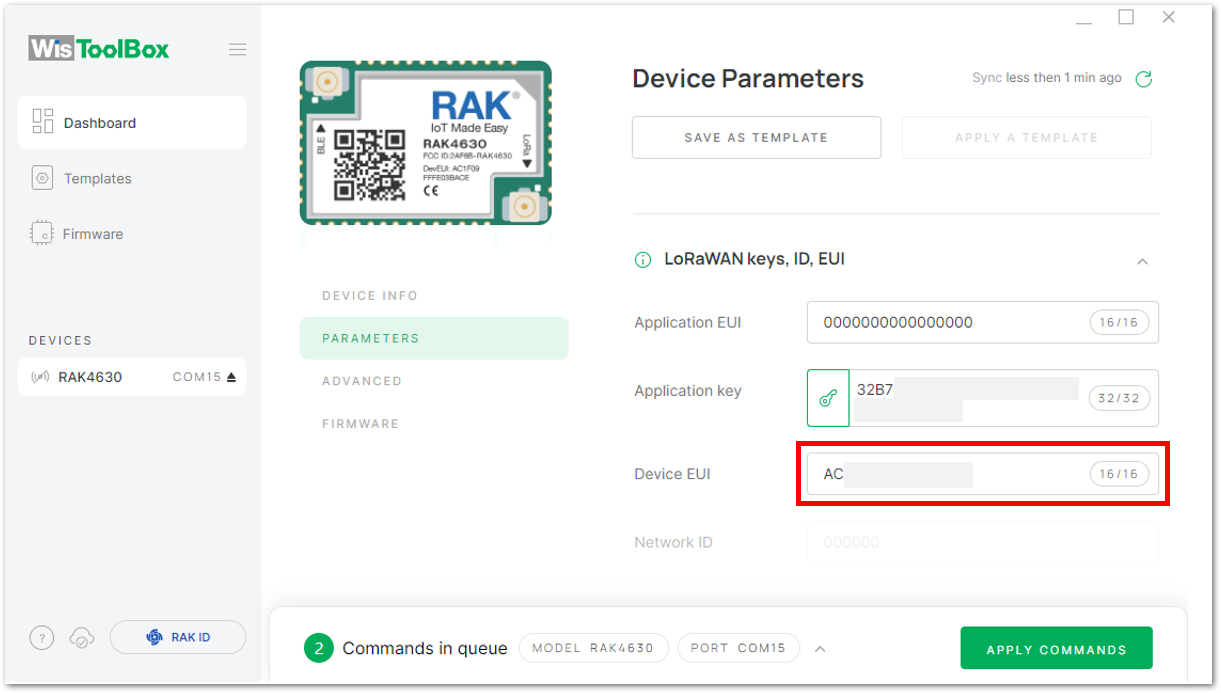 Figure 1: Copying the DevEUI credential from TTN to WisToolBox
- WisToolBox Dashboard
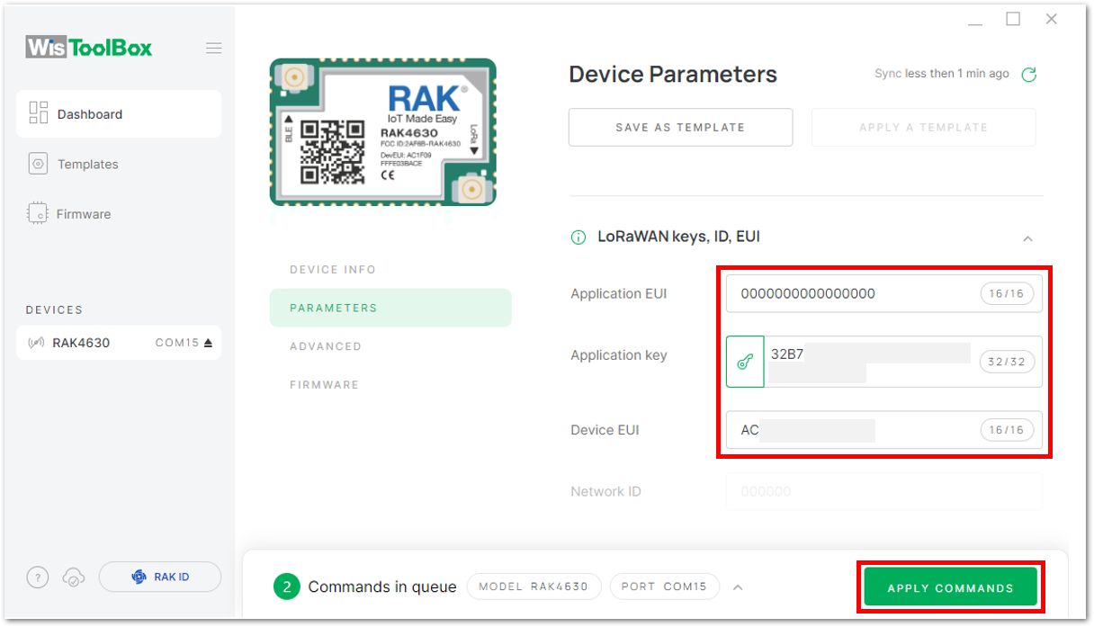 Figure 1: Used credentials from your console in WisToolBox dashboard
- Once completed, you will see a summary of the commands that have been applied to your device, then click on CLOSE.
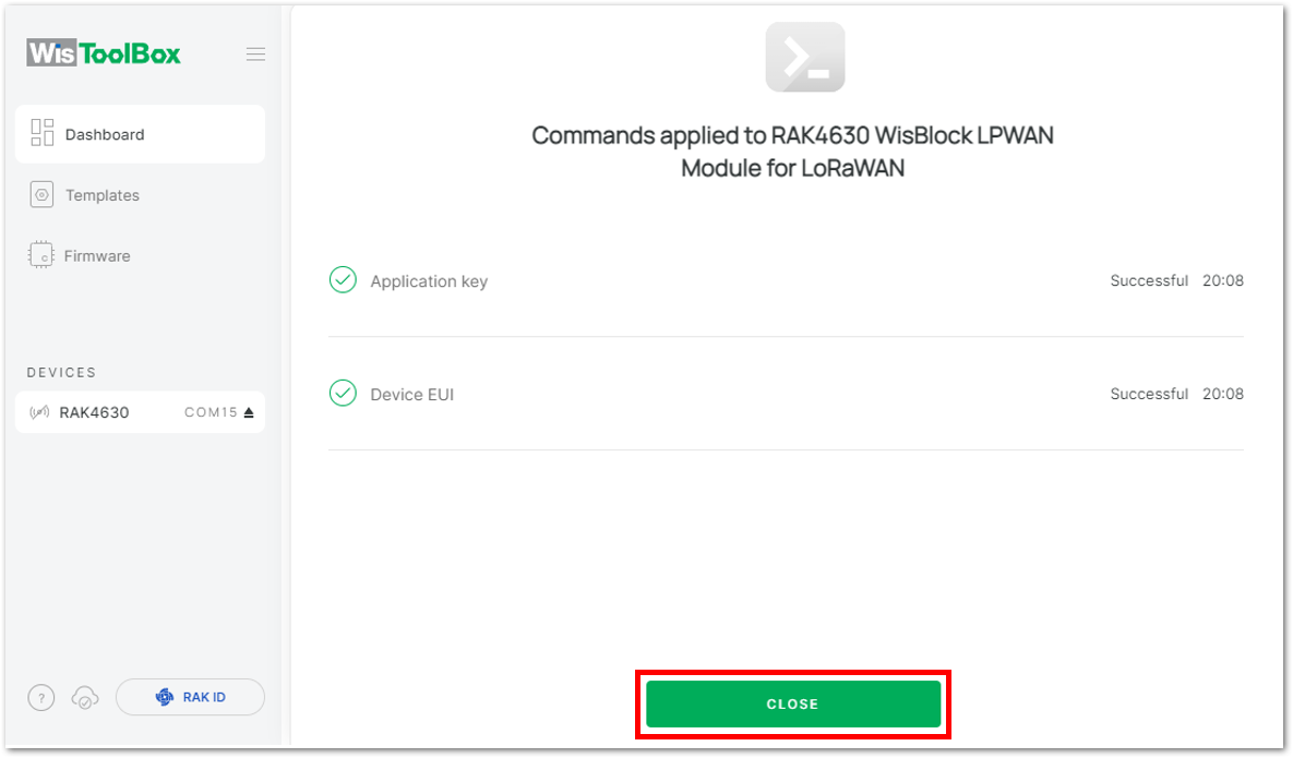 Figure 1: Summary of commands
- Then, it will return to the dashboard with updated credentials of your device.
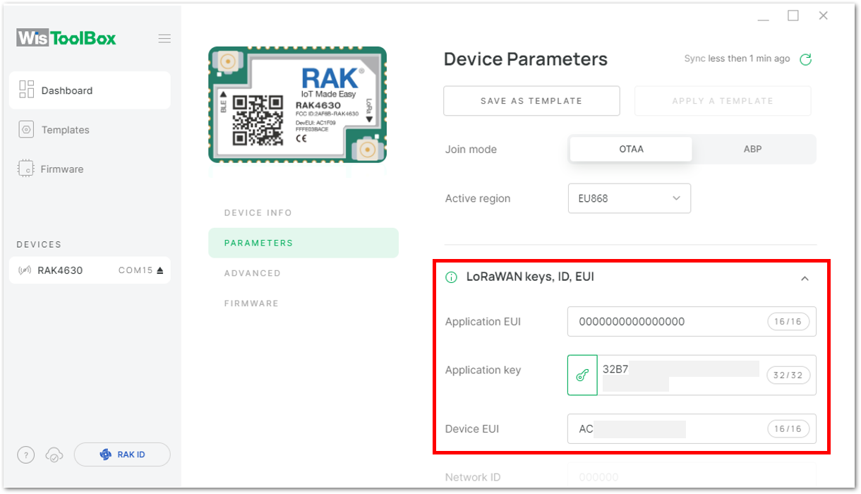 Figure 1: Successfully configured OTAA device via WisToolBox dashboard
- After your device's credentials are updated, it can now join the network. To do this, navigate to Data on LoRa network under PARAMETERS. Then, click on JOIN NETWORK under LoRaWAN join settings. After a few seconds, it will notify you that your OTAA device has successfully joined the TTN server. You can also check your TTN console to confirm if your device has successfully joined TTN.
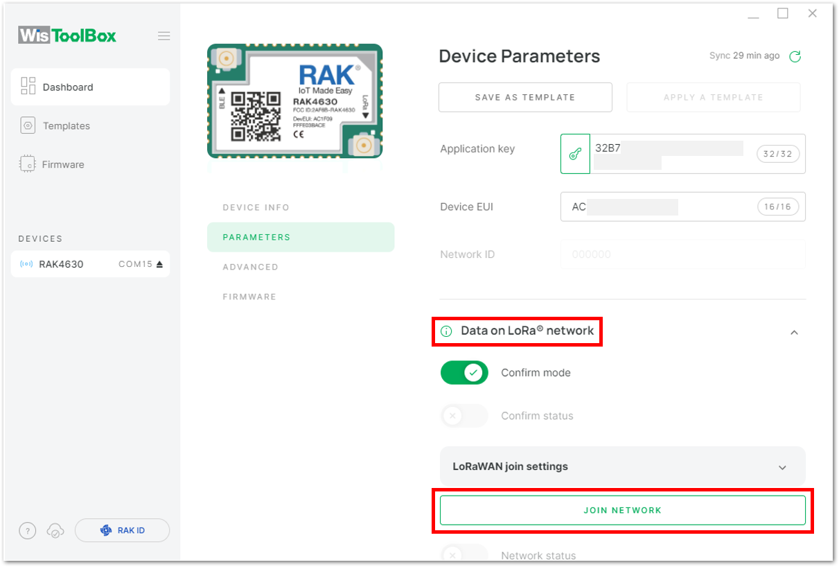 Figure 1: Joining mode of your OTAA device
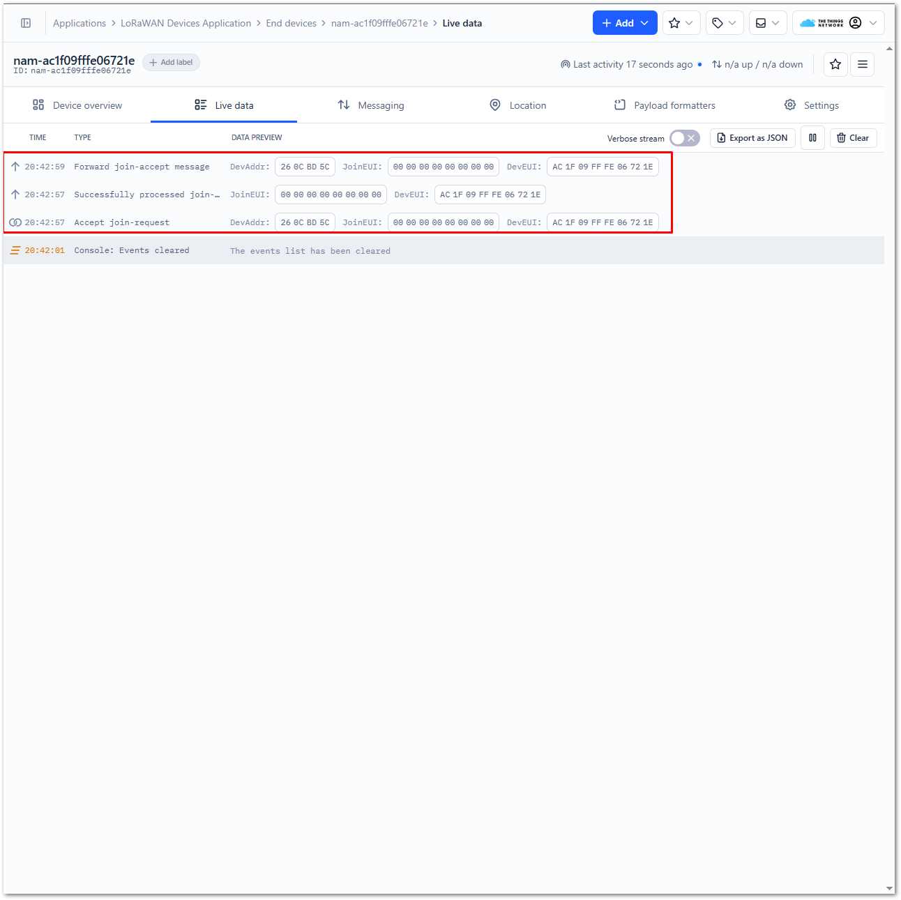 Figure 1: OTAA device successfully joined the TTN server
OTAA Configuration for TTN via WisToolBox Console
Here's another way of OTAA configuration using WisToolBox Console. Below are the steps on setting up your device using WisToolBox Console.
- Open the WisToolBox application.
- Click the CONNECT DEVICE button to launch the WisToolBox Dashboard.
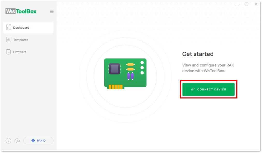 Figure 1: CONNECT DEVICE
- Then select your target port where your device is connected. Once recognized, click CONNECT.
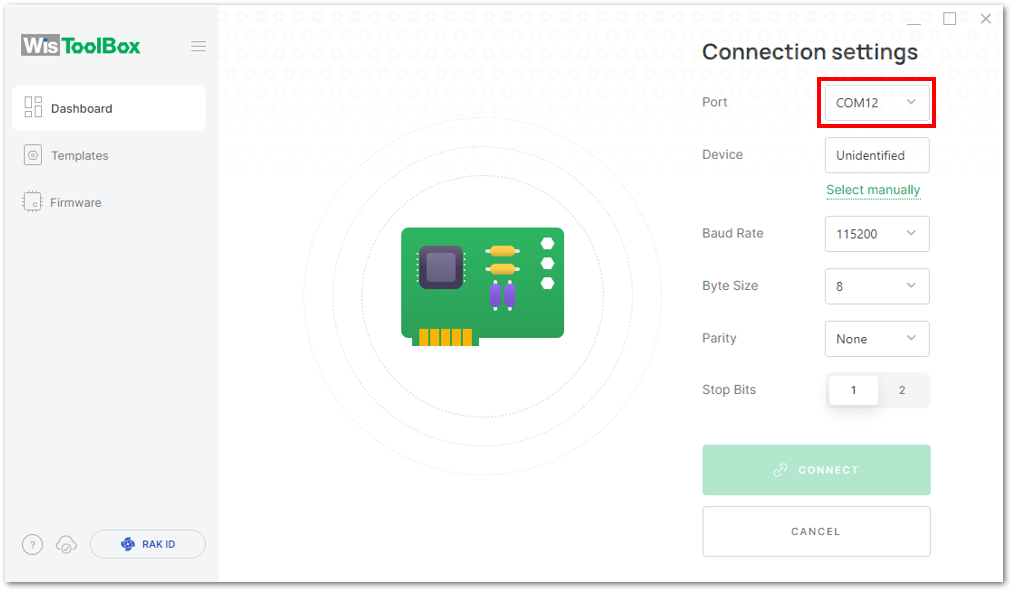 Figure 1: Setting up your device
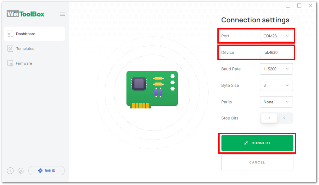 Figure 1: Setting up your device
- Once completed, the device will appear in the dashboard. Select it from the list.
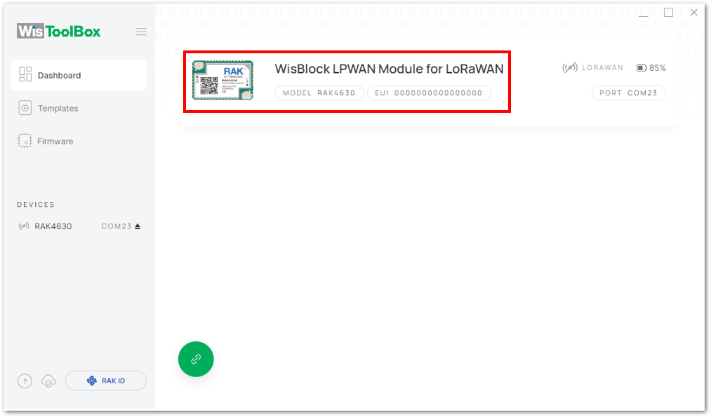 Figure 1: Device seen from WisToolBox dashboard
- Then, click ADVANCED.
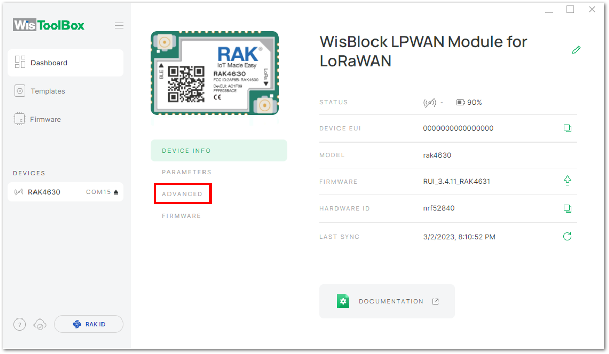 Figure 1: Setting up your device
- Click on OPEN CONSOLE to proceed with the configuration.
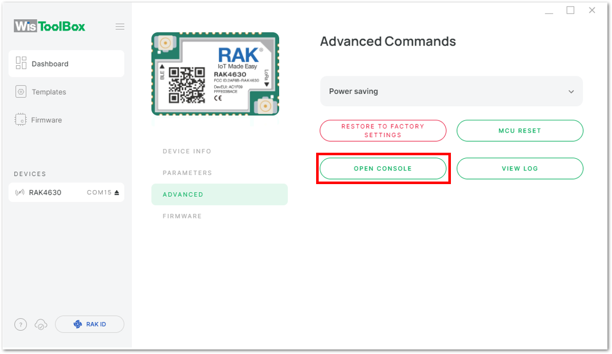 Figure 1: OPEN CONSOLE
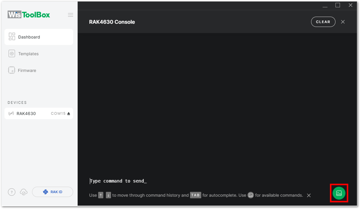 Figure 1: Opening the Console terminal of WisToolBox
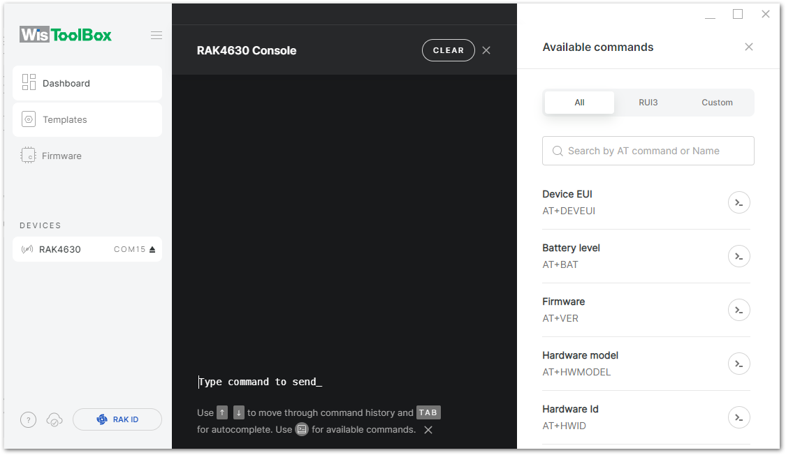 Figure 1: Opening the Console terminal of WisToolBox
- To start the configuration, type
ATEto enable command echo for the configuration commands you input, and then press Enter.
It is recommended to start by testing the console and verify that the current configuration is working by sending these two AT commands:
AT
ATE
ATE is useful for tracking the commands and troubleshooting.
You will receive OK after inputting these two commands. Once ATE is set, you will see all the commands you input along with their replies.
If there is no OK or any reply, check if the device is powered correctly. If you are getting power from a USB port, ensure that you have a good USB cable.
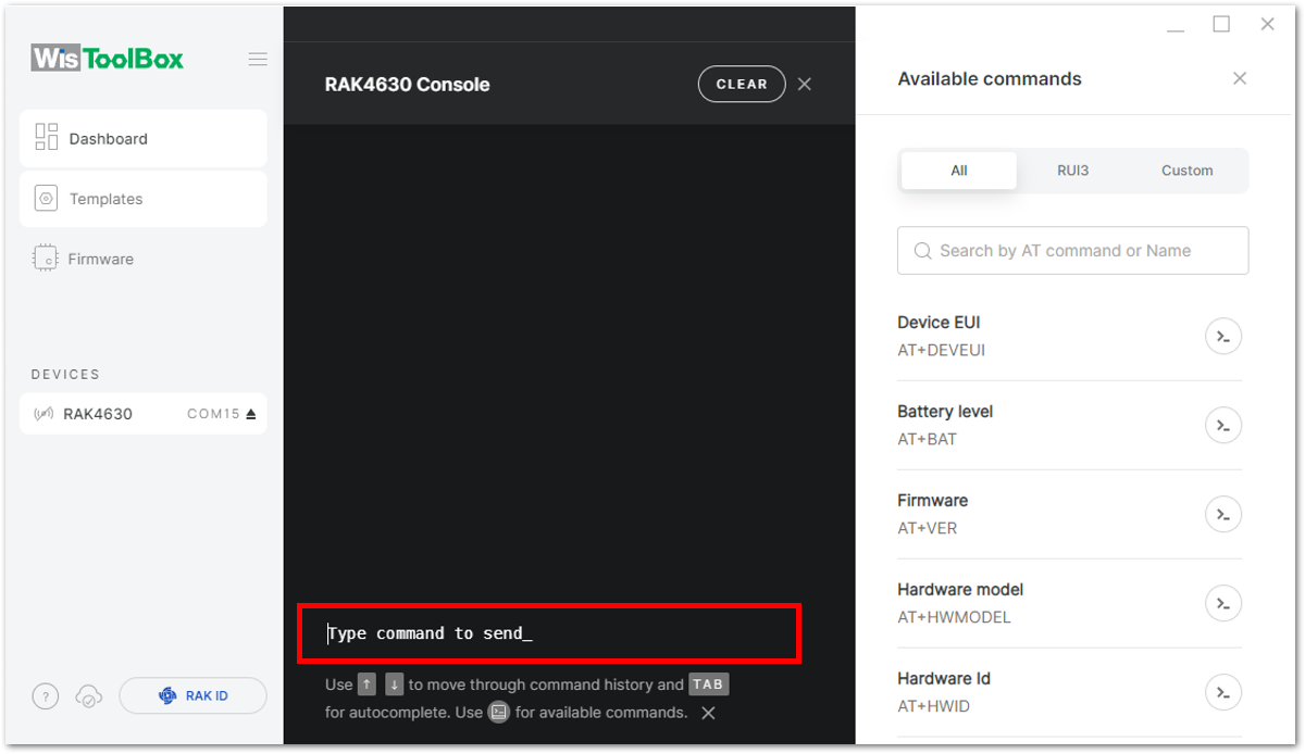 Figure 1: Setting up your Console
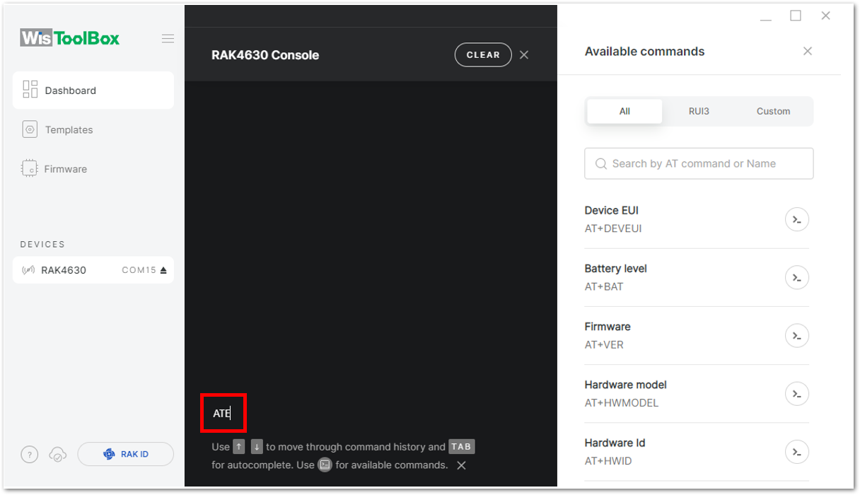 Figure 1: Typing ATE Command
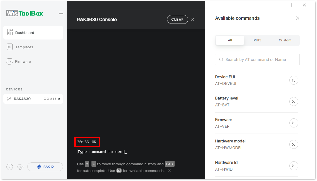 Figure 1: Receiving Replyb on the Console
- Set the LoRaWAN join mode to OTAA. To check the available parameter options, enter
AT+NJM?in the serial terminal and press Enter. To enable OTAA, enterAT+NJM=1and press Enter.
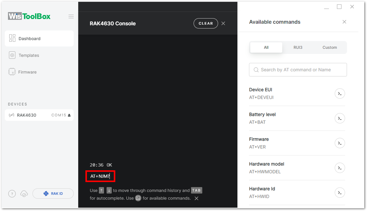 Figure 1: Setting up your Console
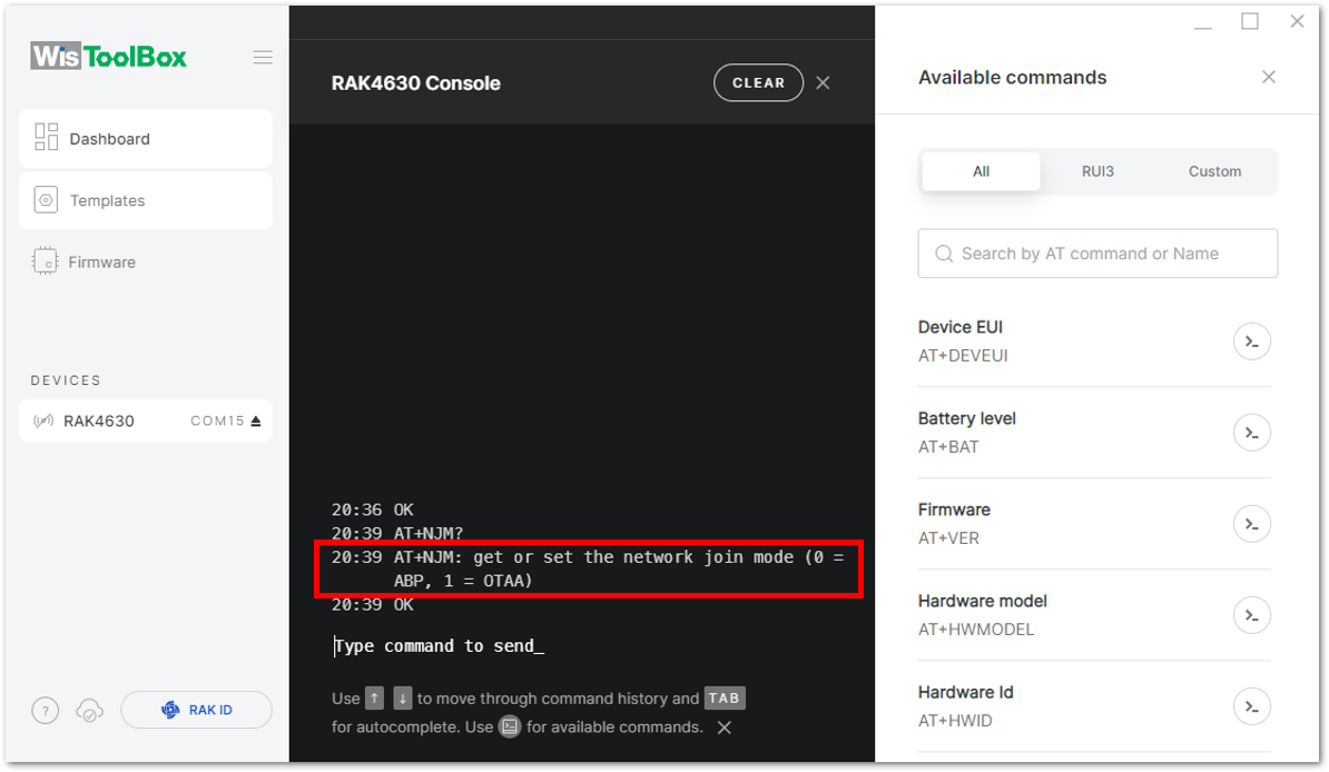 Figure 1: Setting up your Console
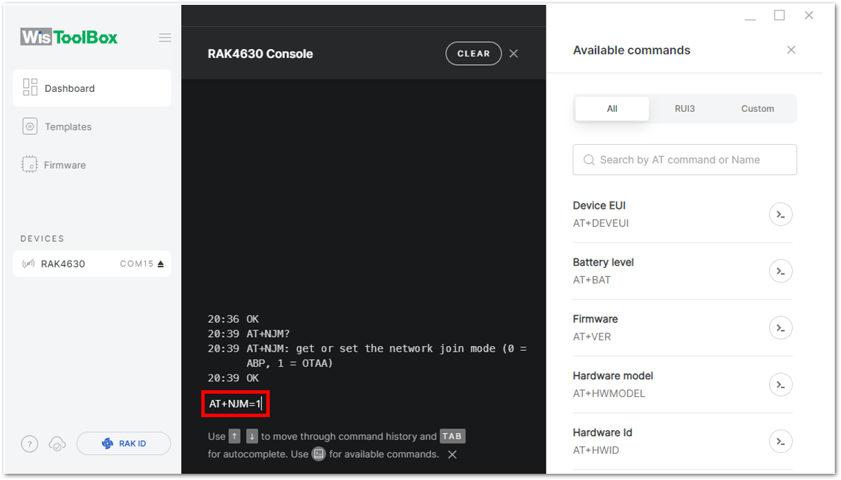 Figure 1: Setting Join Mode to OTAA
- Configure the LoRaWAN region to EU868. To check the available regional band parameters, enter
AT+BAND?in the serial terminal and press Enter.
For EU868, enter AT+BAND=4 and press Enter. If you use a different region, enter the corresponding parameter from the list of supported band parameters below.
-
EU433=0
-
CN470=1
-
RU864=2
-
IN865=3
-
EU868=4
-
US915=5
-
AU915=6
-
KR920=7
-
AS923-1=8
-
AS923-2=9
-
AS923-3=10
-
AS923-4=11
Depending on the Regional Band you selected, you might need to configure the sub-band of your device to match the gateway and LoRaWAN network server. This is especially important for Regional Bands like US915, AU915, and CN470.
Use the AT+MASK command to configure the channel mask. For details, refer to the AT Command Manual.
For example, to configure sub-band 2, enter AT+MASK=0002.
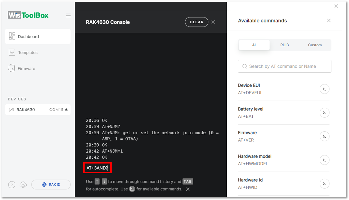 Figure 1: Setting up your Console
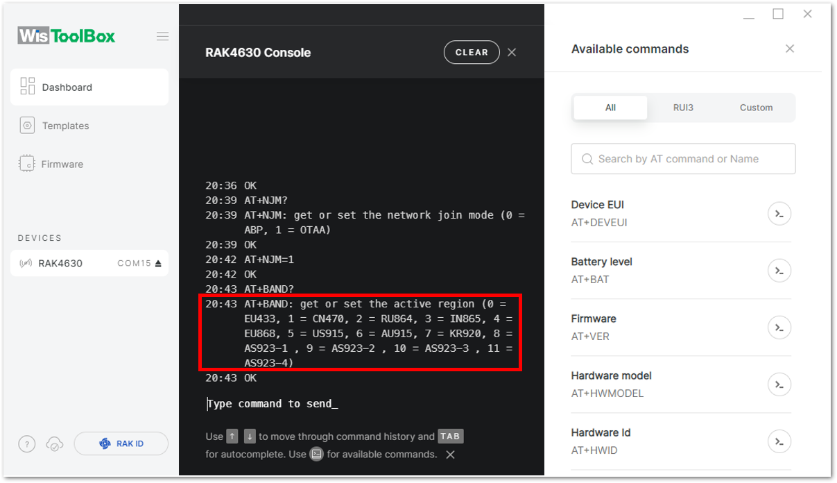 Figure 1: Setting up your Console
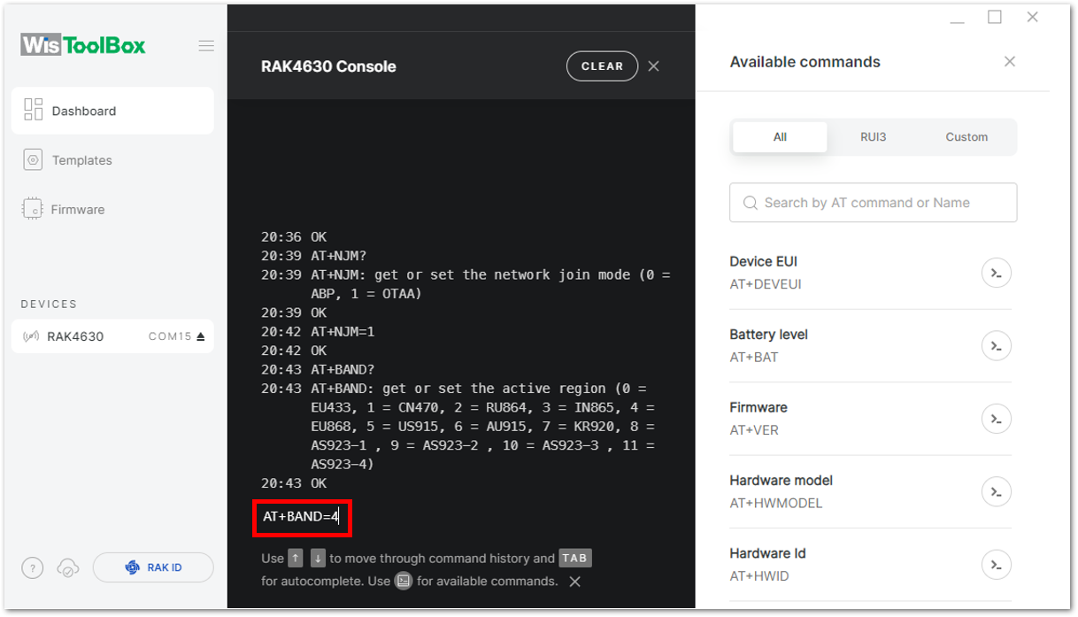 Figure 1: Setting up your Console
- Next, you need to update the OTAA credentials of the module in WisToolBox. For each credential, copy its value from the TTN Console, enter it in the WisToolBox Console, and press Enter.
- For AppEUI
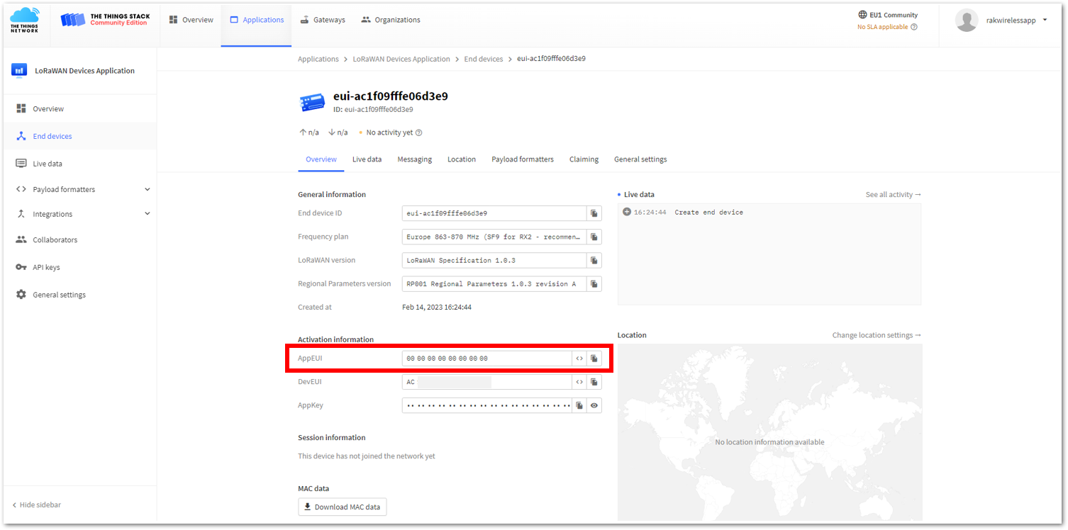 Figure 1: AppEUI in TTN Console
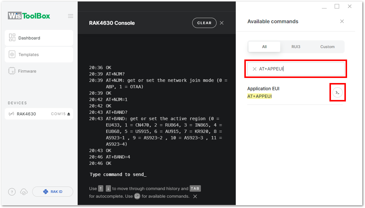 Figure 1: Configuring AppEUI in WisToolBox
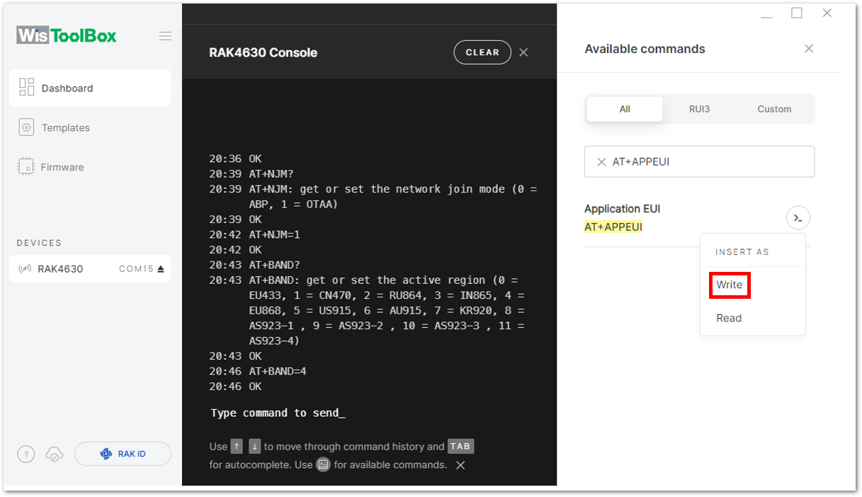 Figure 1: Configuring AppEUI in WisToolBox
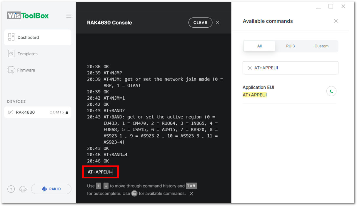 Figure 1: Configuring AppEUI in WisToolBox
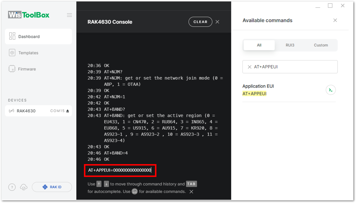 Figure 1: Configuring AppEUI in WisToolBox
- For Application key (AppKey)
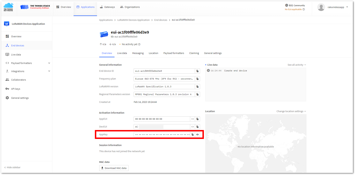 Figure 1: AppKey in TTN Console
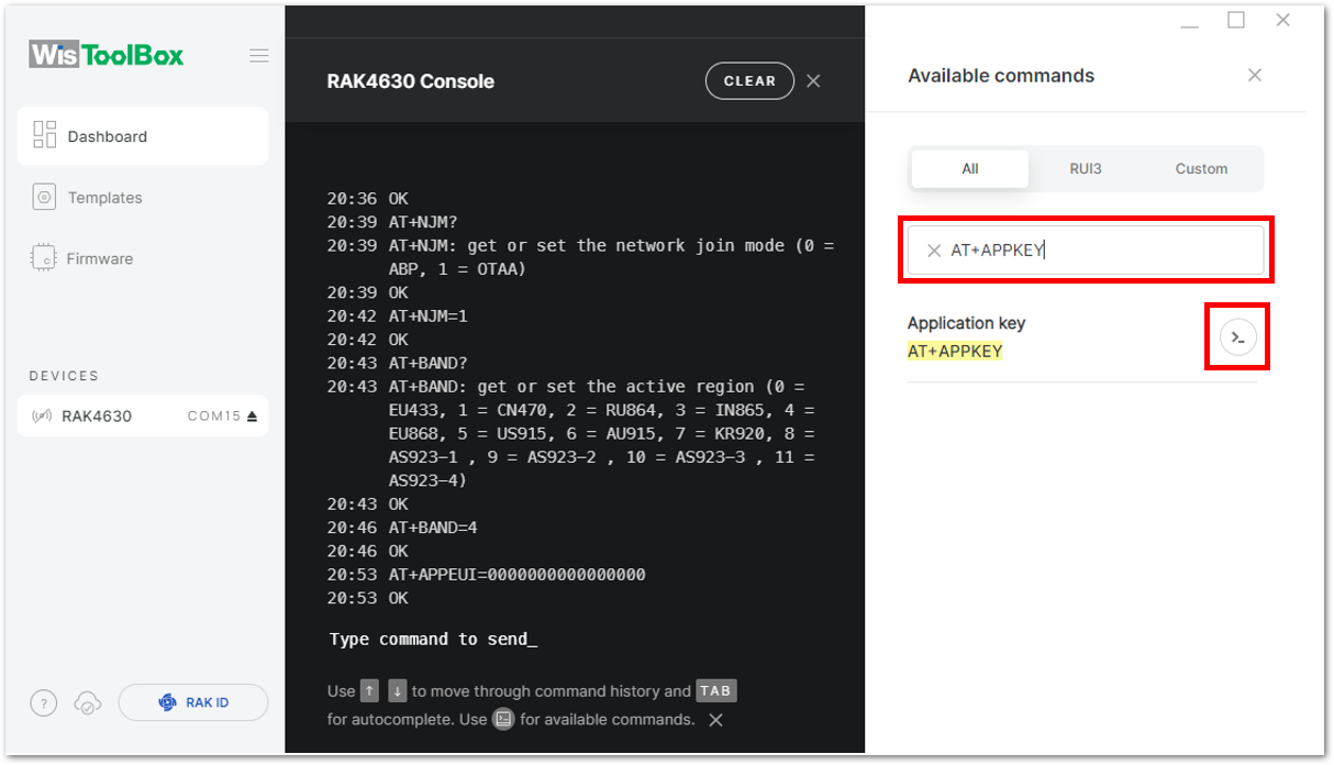 Figure 1: Configuring AppKey in WisToolBox
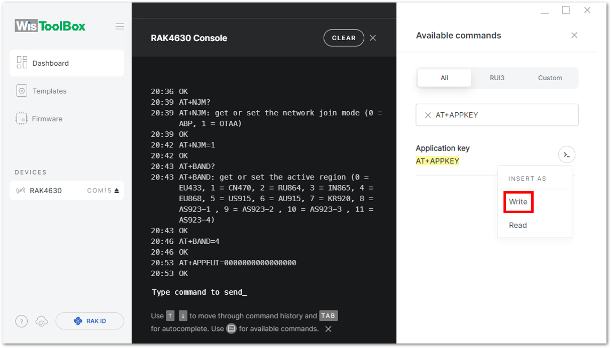 Figure 1: Setting up your Console
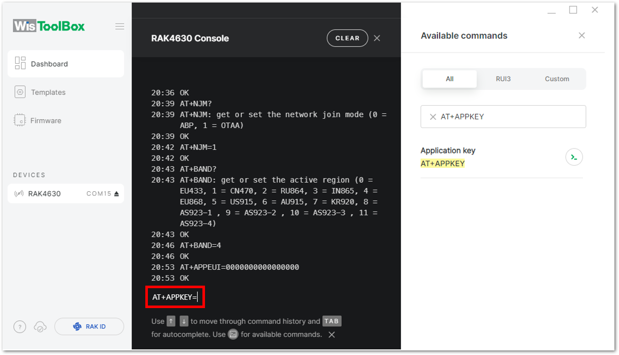 Figure 1: Configuring AppKey in WisToolBox
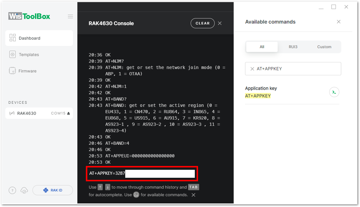 Figure 1: Configuring AppKey in WisToolBox
- For DevEUI
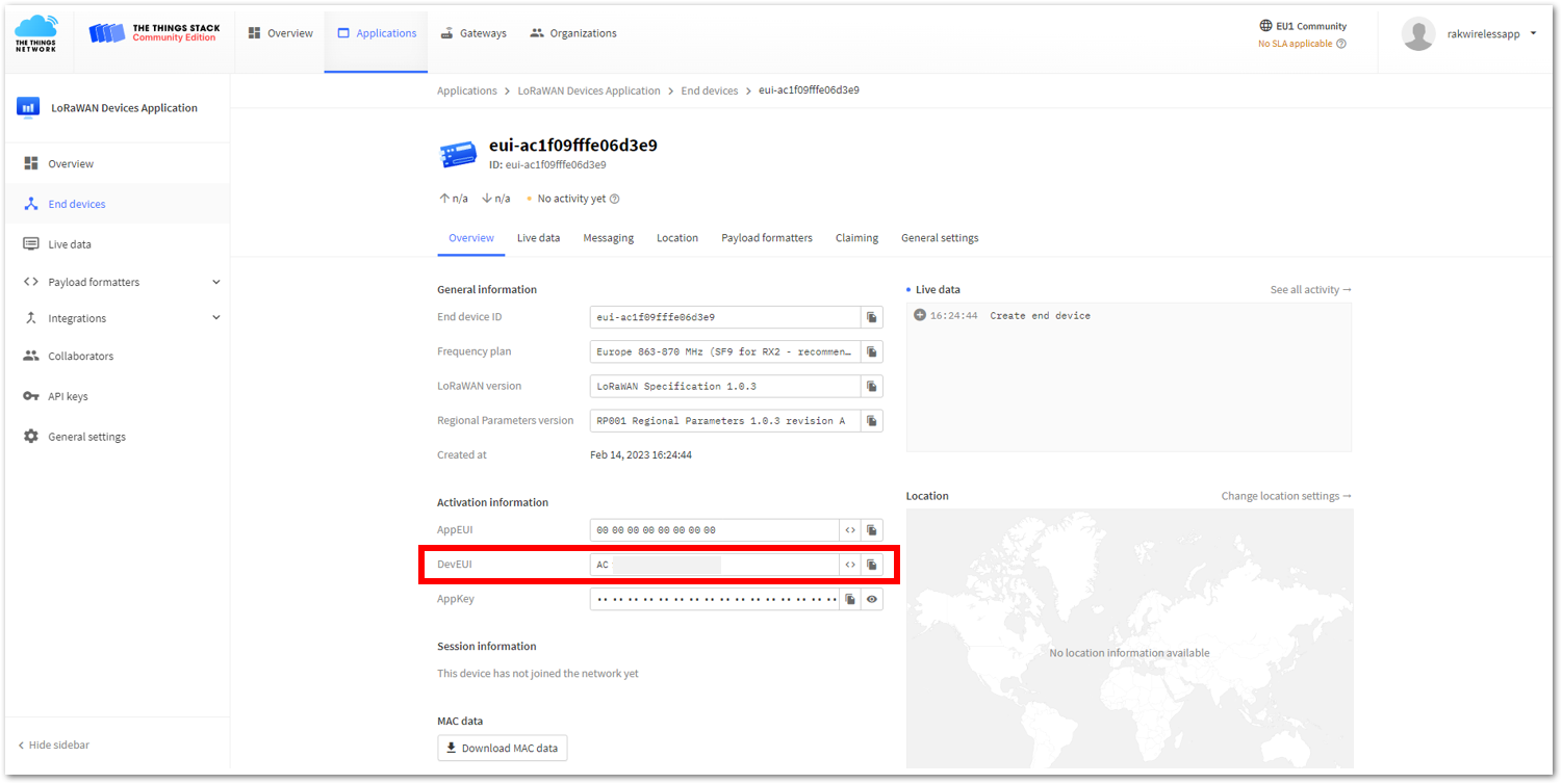 Figure 1: DevEUI in TTN Console
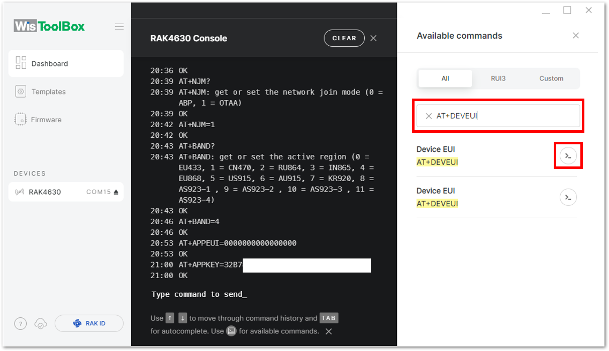 Figure 1: Configuring DevEUI in WisToolBox
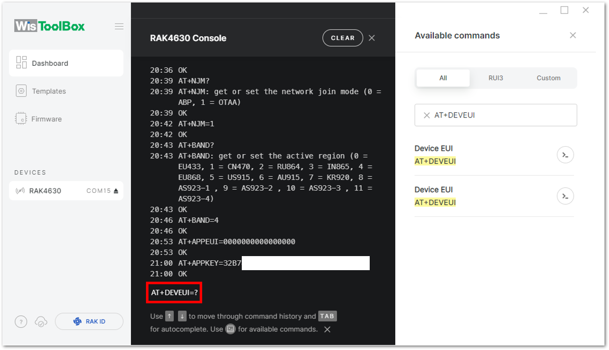 Figure 1: Setting up your Console
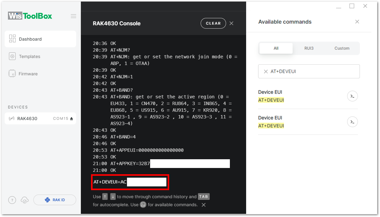 Figure 1: Configuring DevEUI in WisToolBox
- Once done, click Dashboard to check the updated OTAA credentials. Then click PARAMETERS and check Global Settings and LoRaWAN keys, ID, EUI to verify that the settings have been updated.
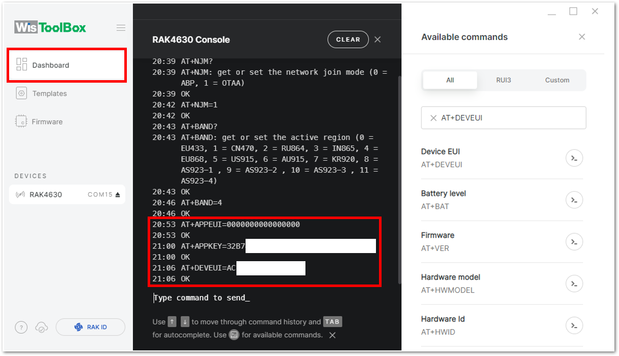 Figure 1: WisToolBox Dashboard
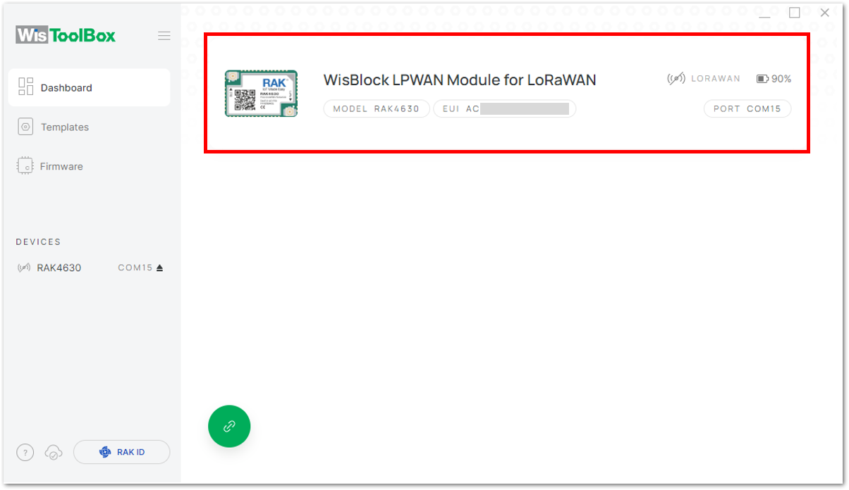 Figure 1: Updated OTAA credentials
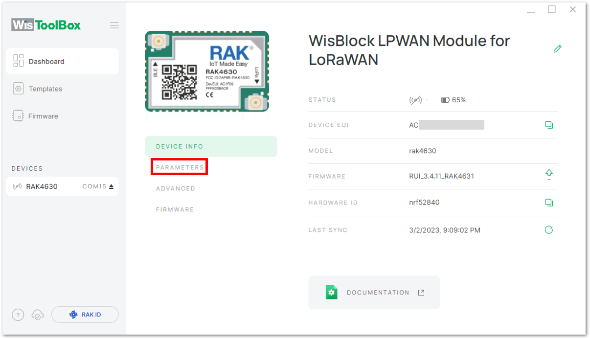 Figure 1: PARAMETERS
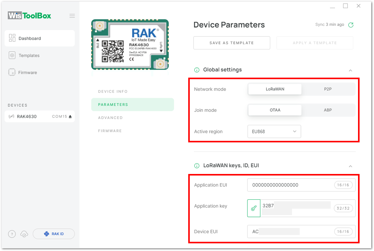 Figure 1: Global settings and LoRaWAN keys, ID, EUI details
-
Your device is now configured for OTAA. You can proceed to join the LoRaWAN network using the WisToolBox Console.
-
Go back to the WisToolBox console and type
AT+JOIN. Edit it toAT+JOIN=1, then press Enter to join the network.
AT+JOINcommand parameters are optional. You can configure the settings for auto-join, reattempt interval, and the number of join attempts if your application needs it. If not configured, it will use the default parameter values.AT+JOINandAT+JOIN=1also share the common functionality of trying to join the network.
Join command format: AT+JOIN=w:x:y:z
| Parameter | Description |
|---|---|
| w | Join command - 1: joining, 0: stop joining. |
| x | Auto-join config - 1: auto-join on power-up, 0: no auto-join |
| y | Reattempt interval in seconds (7-255) - 8 is the default. |
| z | Number of join attempts (0-255) - 0 is the default. |
After 5 or 6 seconds, if the request is successfully received by a LoRa gateway, you should see a +EVT:JOINED status reply.
If the OTAA device failed to join, you need to check if your device is within reach of a working LoRaWAN gateway that is configured to connect to TTN. It is also important to check that all your OTAA parameters (DEVEUI, APPEUI, and APPKEY) are correct using the AT+DEVEUI=?, AT+APPEUI=?, and AT+APPKEY=? commands. Lastly, ensure that the antenna of your device is properly connected.
After checking all the things above, try to join again.
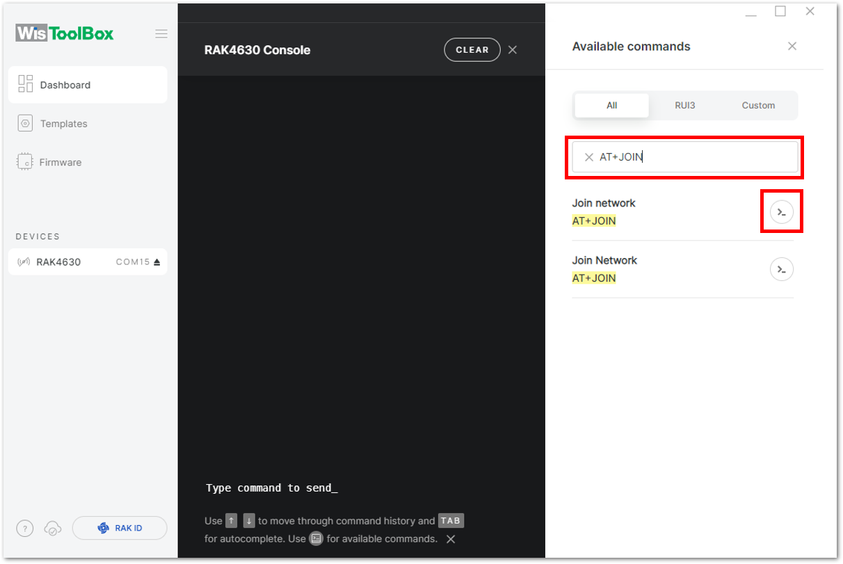 Figure 1: Joining mode using WisToolBox Console
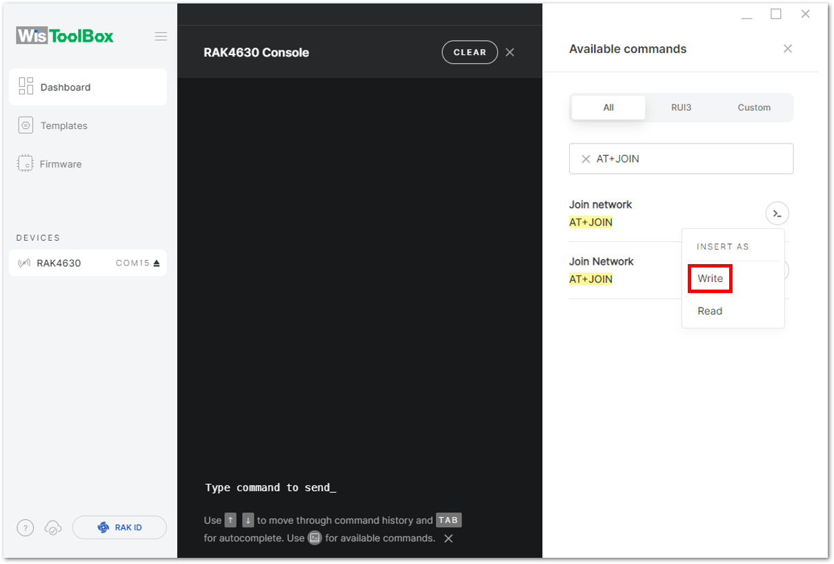 Figure 1: Joining mode using WisToolBox Console
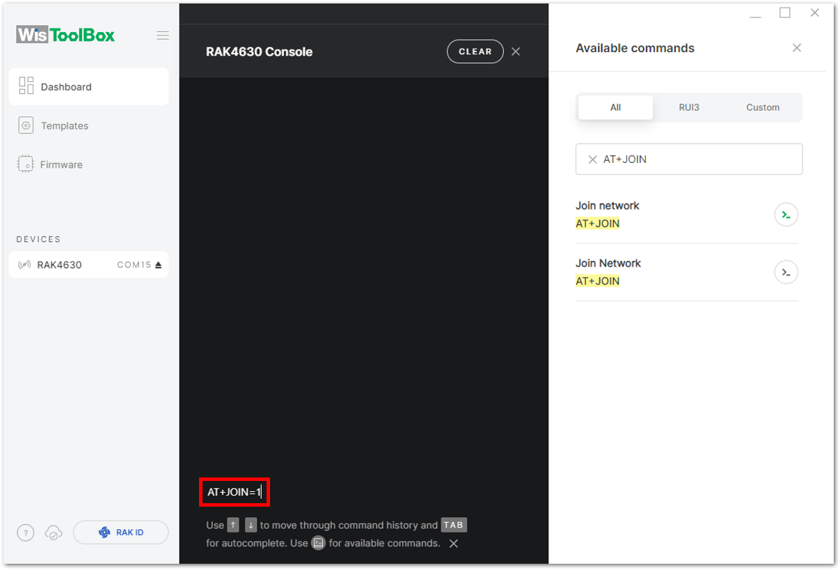 Figure 1: Joining mode using WisToolBox Console
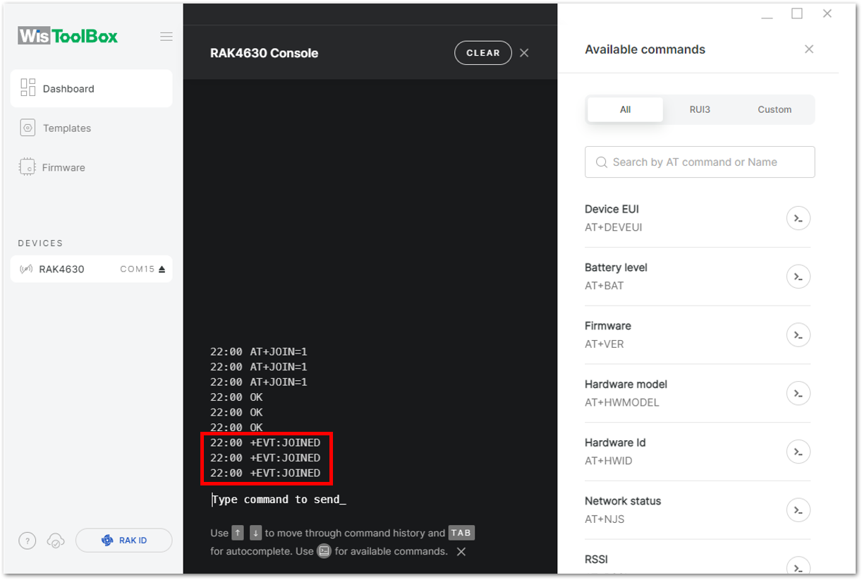 Figure 1: OTAA device successfully joined the network
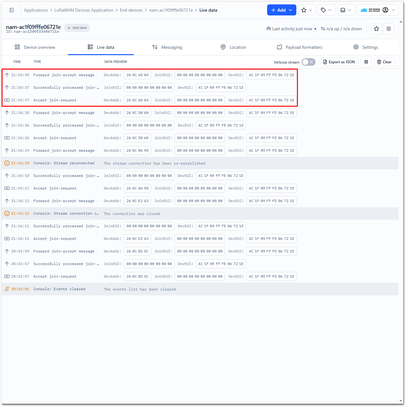 Figure 1: OTAA device successfully joined the network
- With the end-device properly joined to the TTN, try to send some payload after a successful join. Send command format:
AT+SEND=<port>:<payload>
AT+SEND=2:12345678
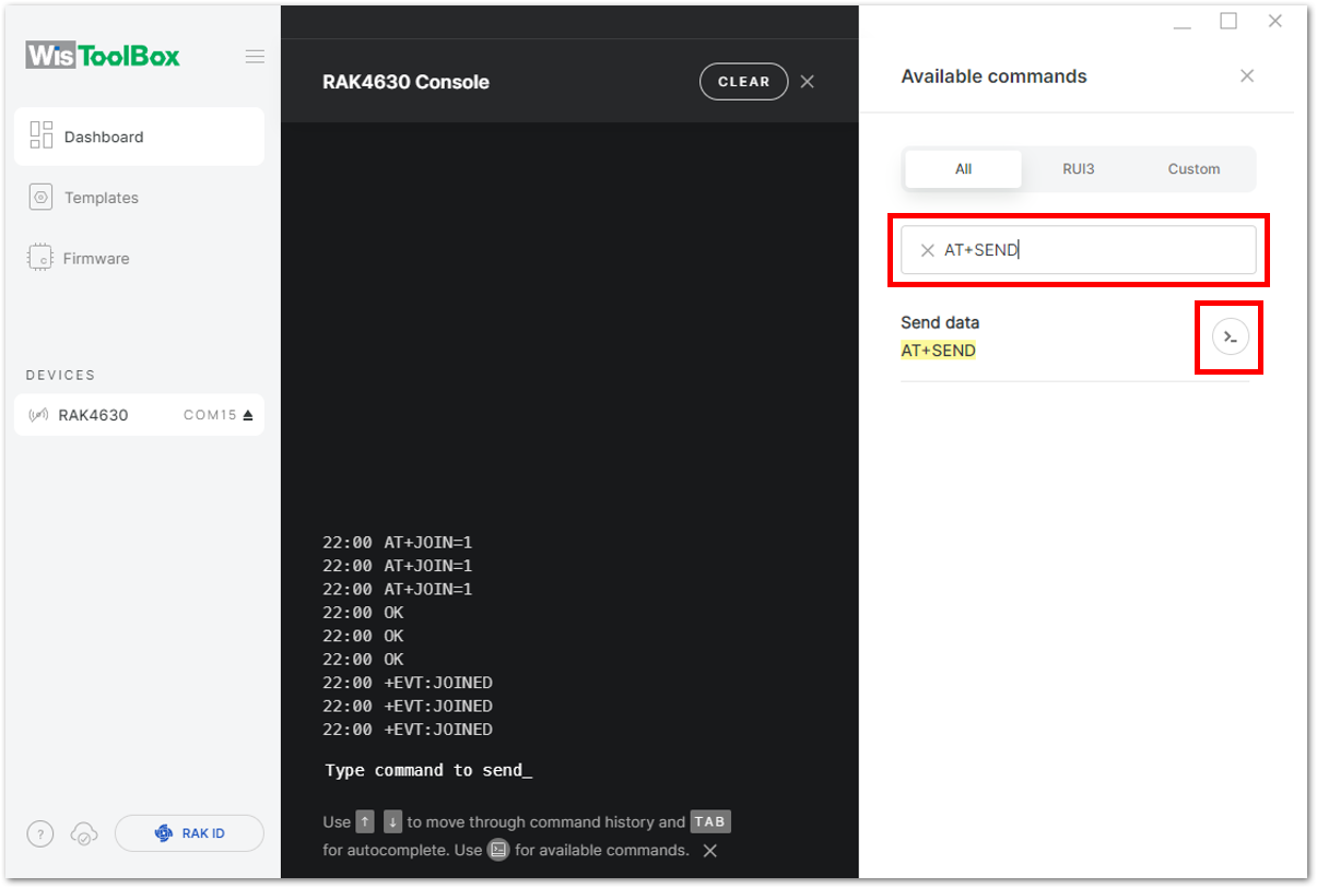 Figure 1: OTAA device sending payload to the network
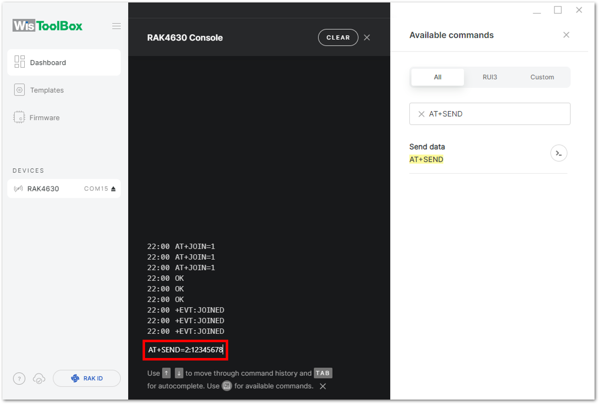 Figure 1: OTAA device sending payload to the network
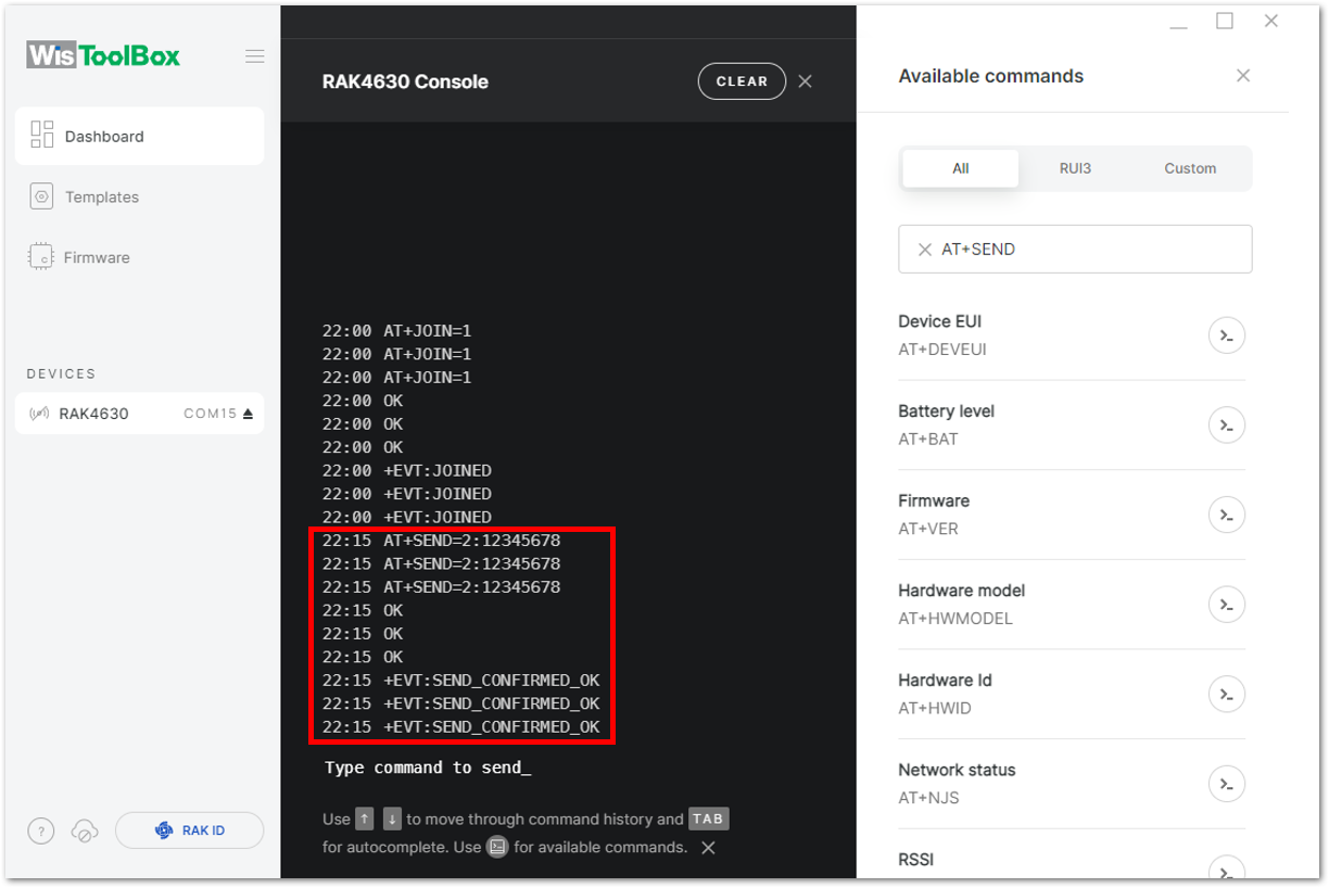 Figure 1: OTAA device sending payload to the network
- You can view the data sent by the device on the TTN console's Live data section. Additionally, the Last seen information should indicate a few seconds or minutes ago.
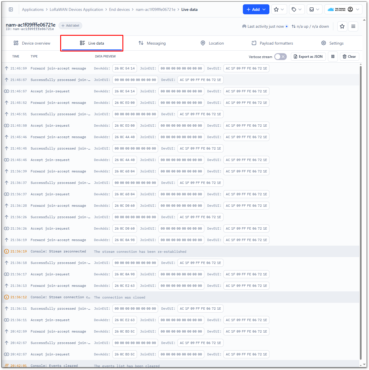 Figure 1: OTAA Test Sample Data Sent Viewed in TTN
ABP Configuration for TTN
RAK modules can be configured using WisToolBox for ABP configuration. WisToolBox is a software tool designed to support the RAK module, automatically detecting the RAK module once connected to the PC. Below are the options available in WisToolBox for ABP configuration:
ABP Configuration for TTN via WisToolBox UI
- Open the WisToolBox application.
- Click the CONNECT DEVICE button to launch the WisToolBox Dashboard.
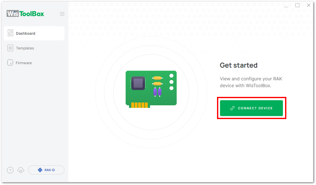 Figure 1: CONNECT DEVICE
- Select your target port where your RAK module is connected. Once recognized, click CONNECT.
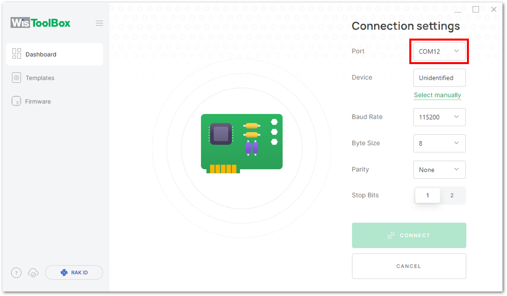 Figure 1: Setting up your device
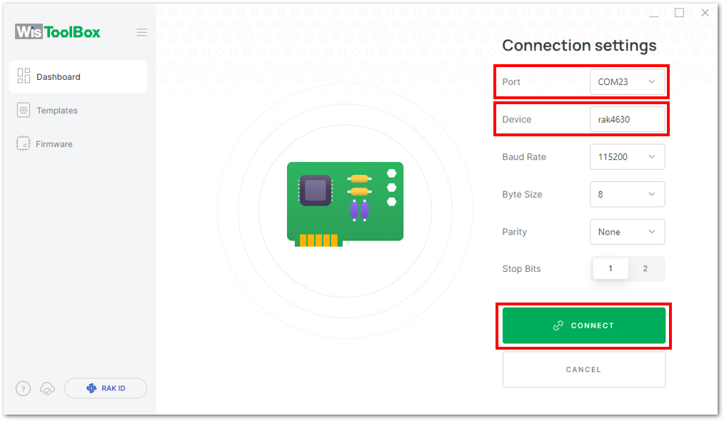 Figure 1: Setting up your device
- The device will appear in the dashboard, Click on it.
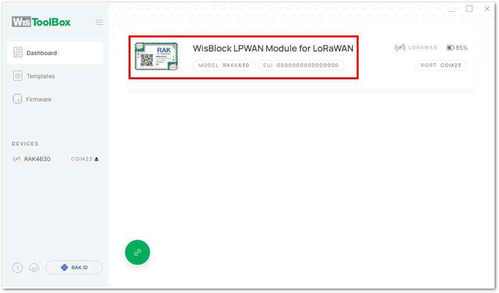 Figure 1: Device seen from WisToolBox dashboard
- Click PARAMETERS to configure the device.
- The AppSKey, Device address, and NwkSKey are hidden in this section as these are unique from a specific device.
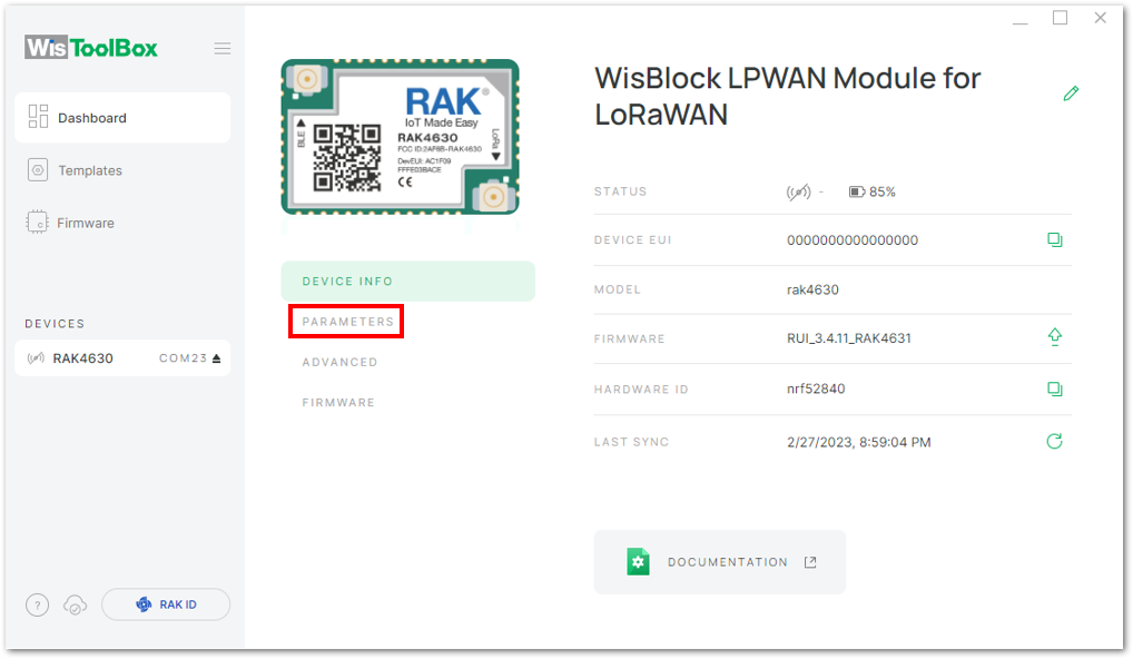 Figure 1: Setting up your device
- Click Global settings to set the network mode to LoRaWAN and the join mode to ABP. Ensure that the active region is set to EU868 for this configuration. If you wish to work on other regional bands, you can choose among the active regions based on your location.
- LoRa network mode: LoRaWAN
- LoRaWAN join mode: ABP
- LoRaWAN region: EU868
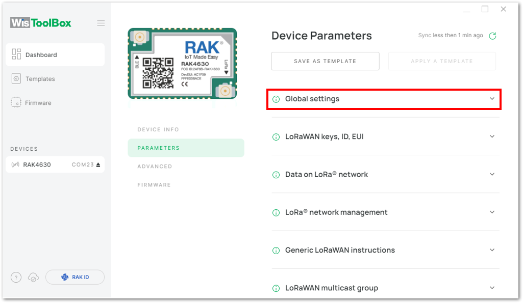 Figure 1: Global settings
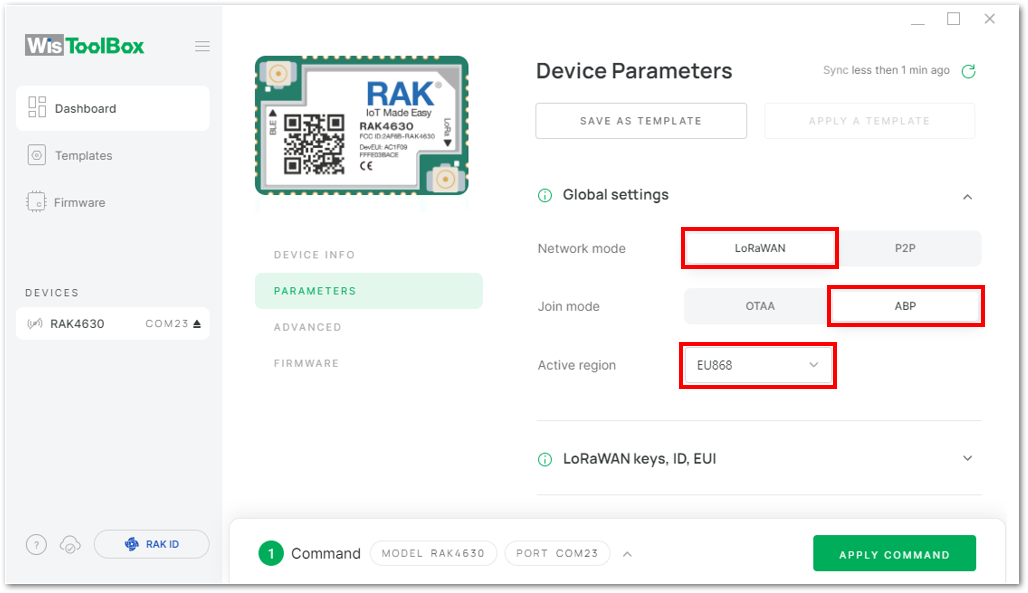 Figure 1: Global settings
- Click LoRaWAN keys, ID, EUI to configure the Application session key (AppSKey), Device address and Network session key (NwkSKey).
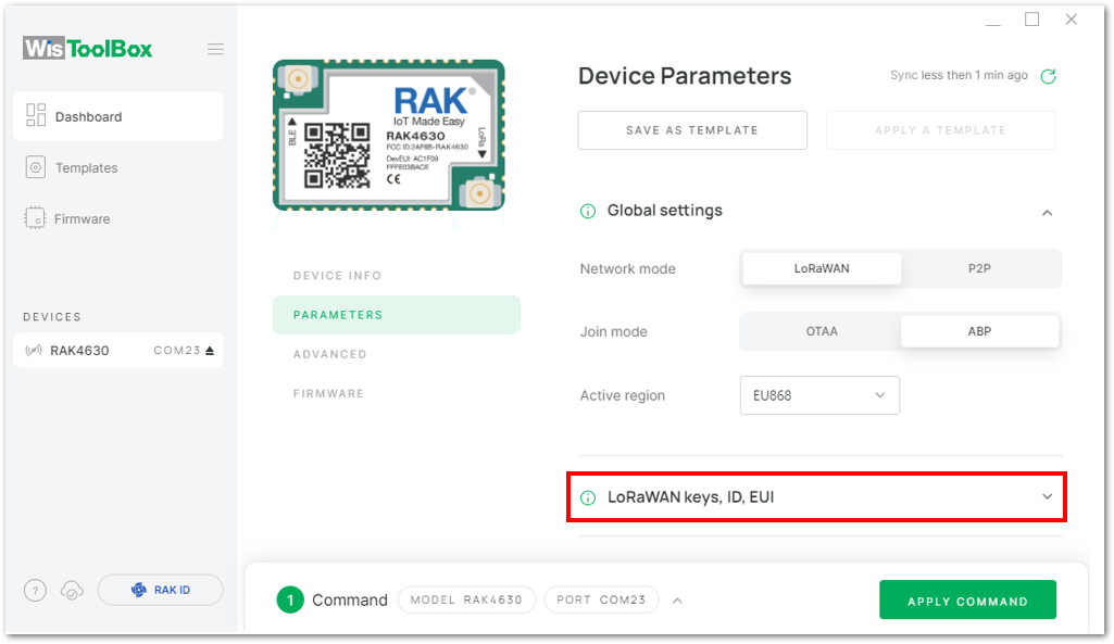 Figure 1: LoRaWAN keys, ID, EUI
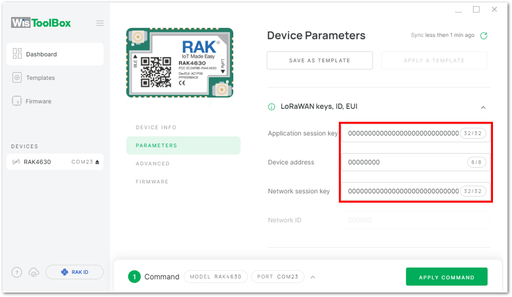 Figure 1: Setting up your device
- Go back to the console where your End device is created previously, then copy all the credentials from there. Those will be the ones to be used also in the WisToolBox dashboard. Once encoded into the dashboard, click APPLY COMMANDS to update your device.
- The AppSKey, Device address, and NwkSKey are hidden in this section as these are unique from a specific device.
- For Application session key (AppSKey)
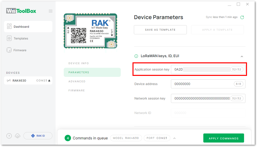 Figure 1: Copying the AppSKey credential from TTN to WisToolBox
- For Device address
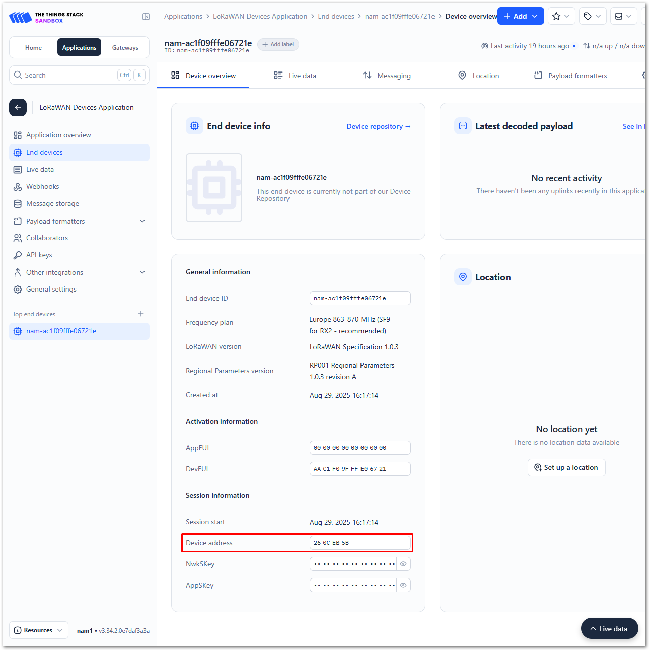 Figure 1: Copying the Device address credential from TTN to WisToolBox
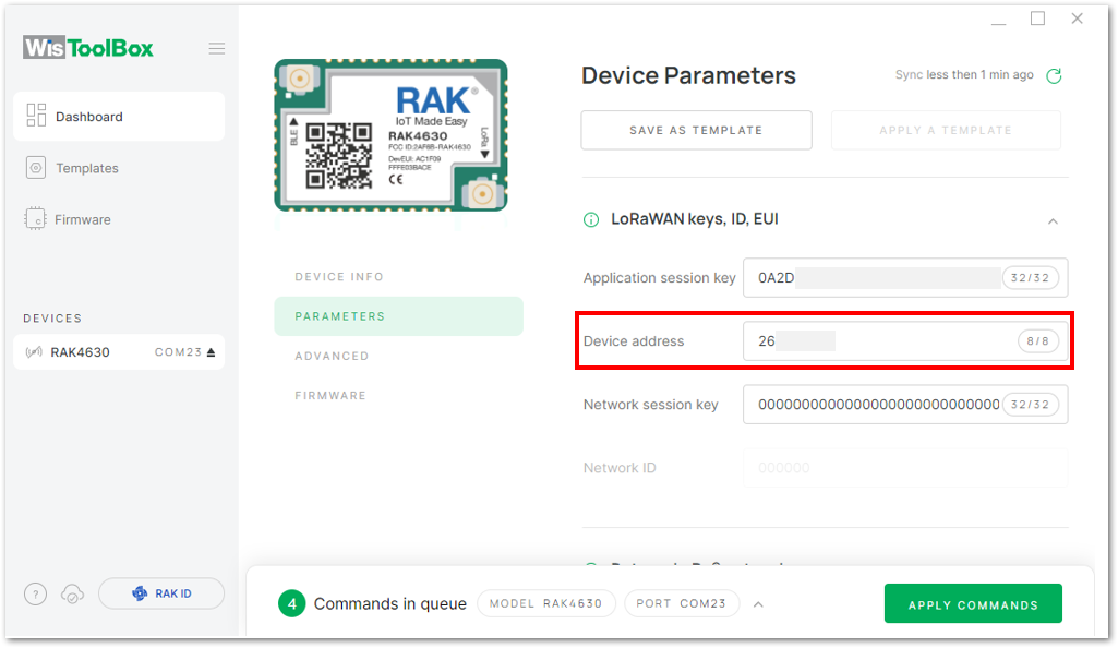 Figure 1: Copying the Device address credential from TTN to WisToolBox
- For Network session key (NwkSKey)
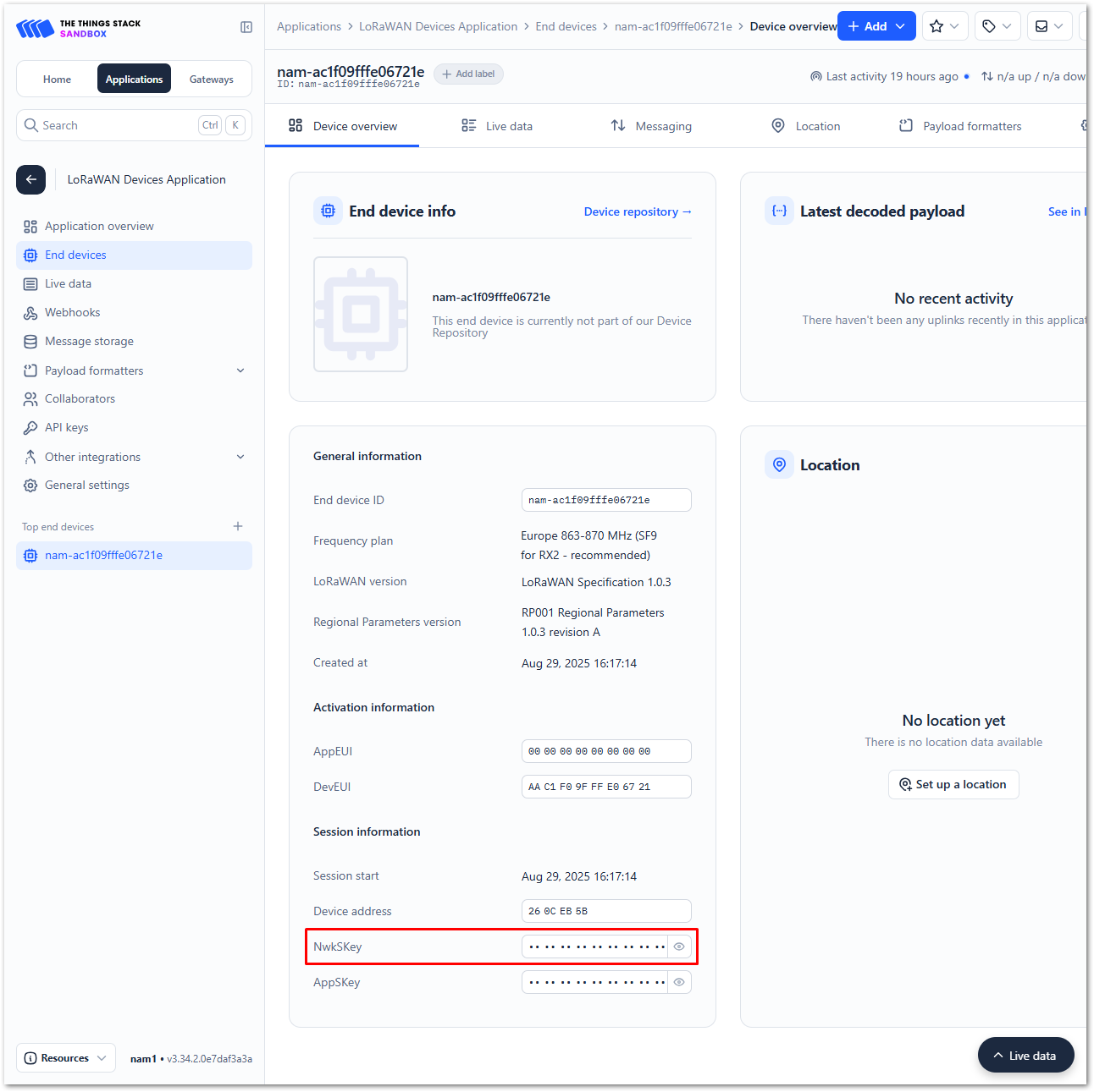 Figure 1: Copying the NwkSKey credential from TTN to WisToolBox
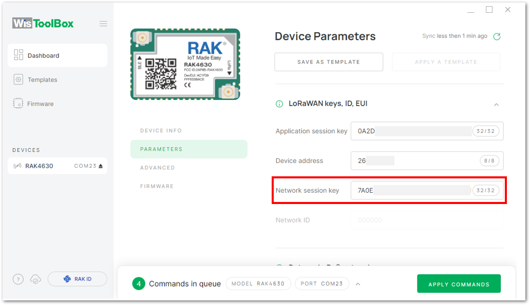 Figure 1: Copying the NwkSKey credential from TTN to WisToolBox
- WisToolBox Dashboard
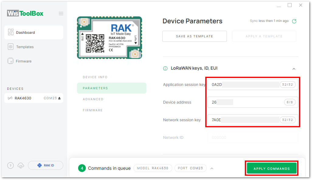 Figure 1: Used credentials from your console in WisToolBox dashboard
- Once completed, you will see a summary of the commands that were applied to your device. Then, click CLOSE.
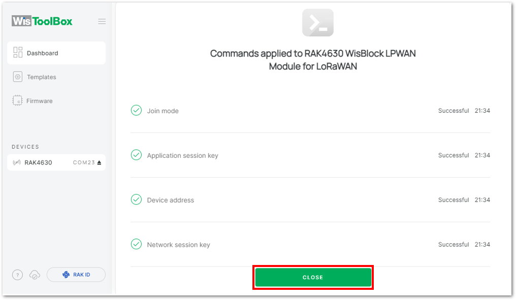 Figure 1: Summary of commands
- Now you will see it returns to the dashboard with updated credentials of your device.
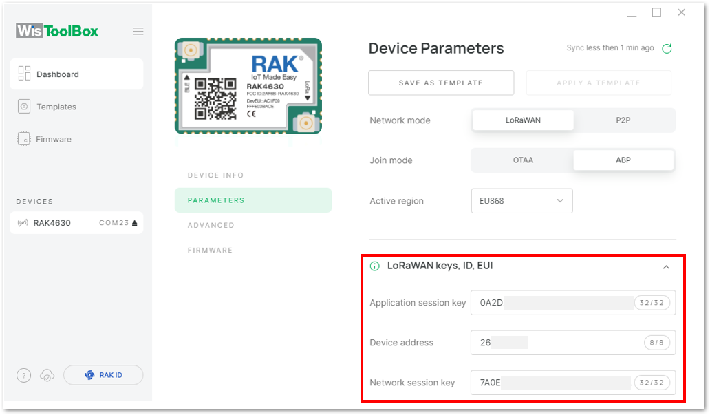 Figure 1: Successfully configured ABP device via WisToolBox dashboard
ABP Configuration for TTN via WisToolBox Console
Here's another way of ABP configuration using WisToolBox Console. Below are the steps on setting up your RAK module using WisToolBox Console.
- Open the WisToolBox application.
- Click the CONNECT DEVICE button to launch the WisToolBox Dashboard.
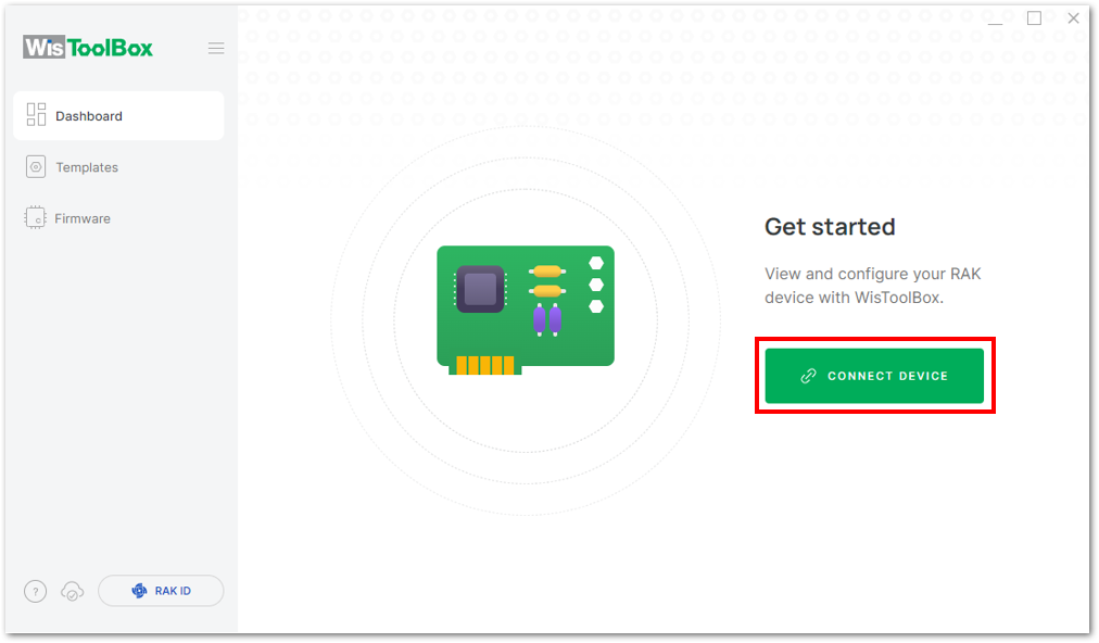 Figure 1: CONNECT DEVICE
- Select your target port where your RAK module is connected. Once recognized, click CONNECT.
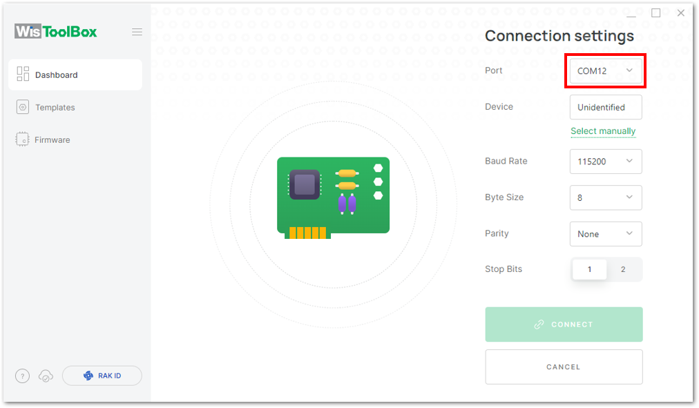 Figure 1: Setting up your device
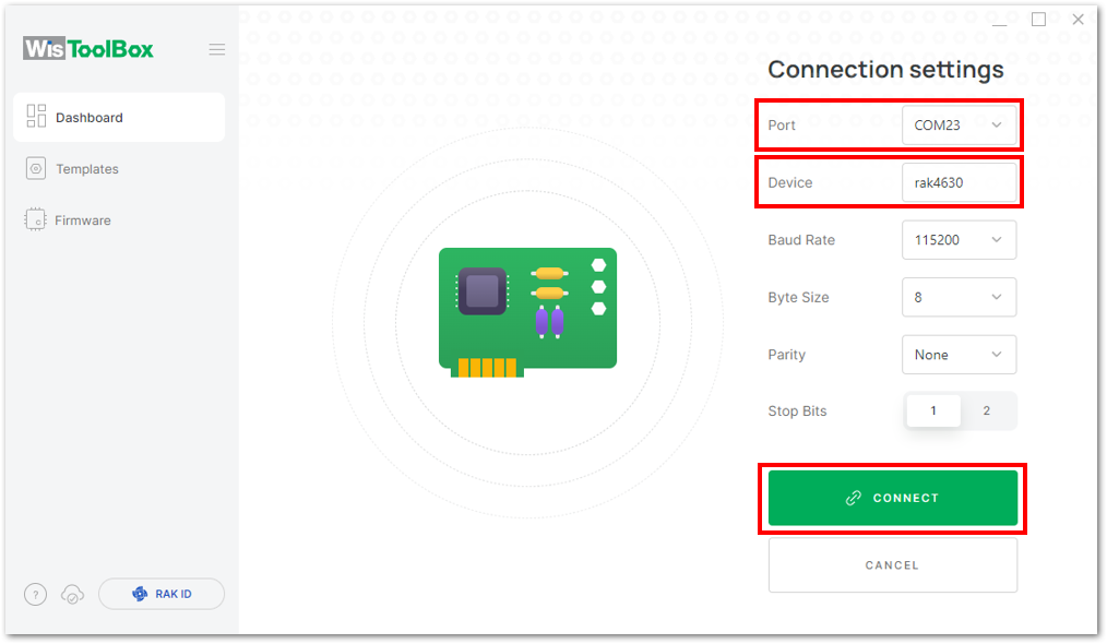 Figure 1: Setting up your device
- Once done, the device will appear in the dashboard, click on it.
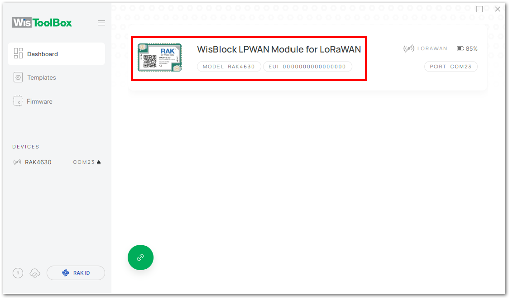 Figure 1: Device seen from WisToolBox dashboard
- Click ADVANCED.
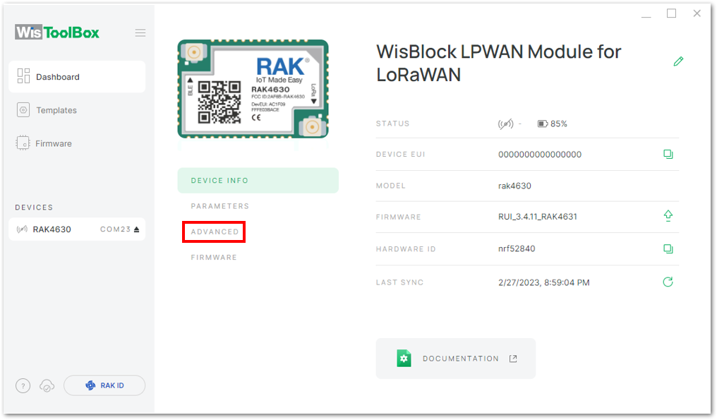 Figure 1: Setting up your device
- click OPEN CONSOLE to proceed with the configuration.
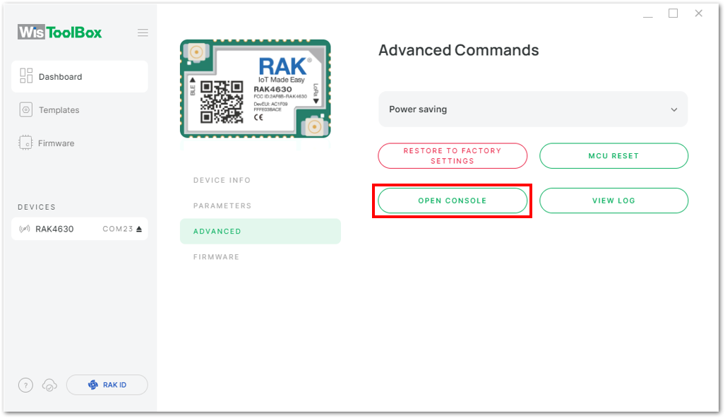 Figure 1: OPEN CONSOLE
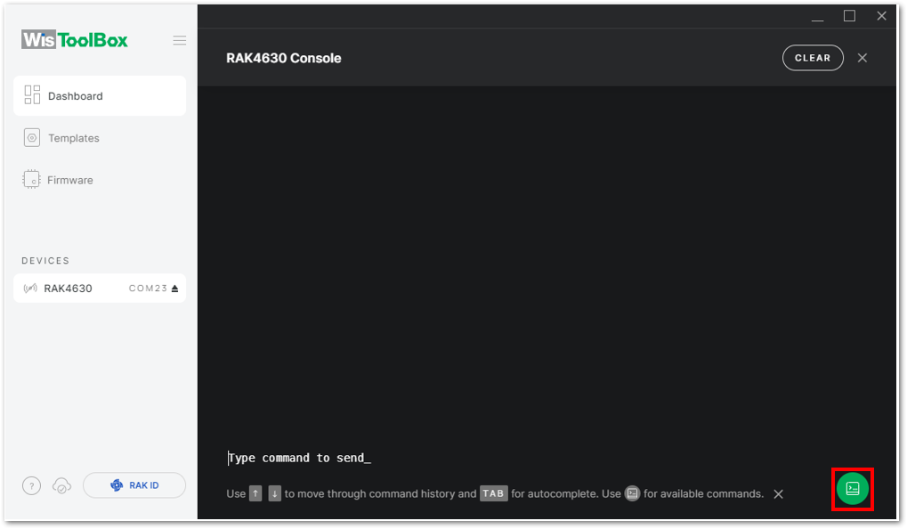 Figure 1: Opening the Console terminal of WisToolBox
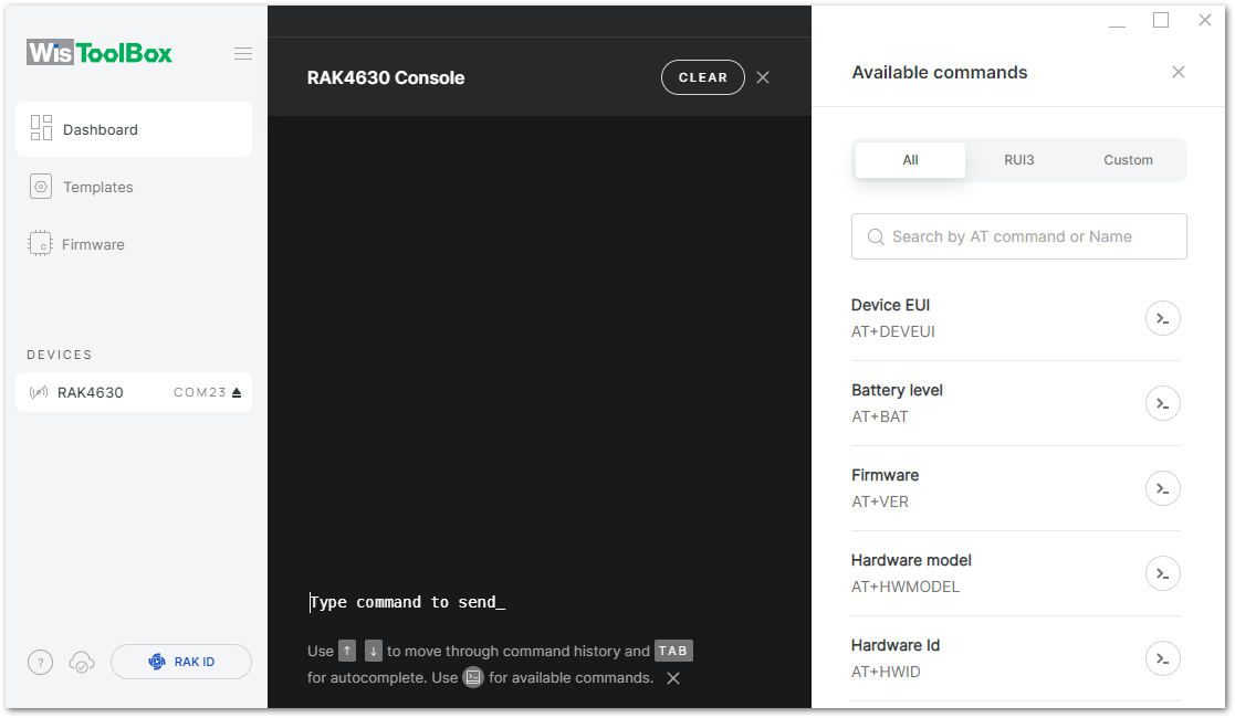 Figure 1: Opening the Console terminal of WisToolBox
- To start the configuration, type ATE so you can echo the commands you input during your configuration. Then press Enter.
It is recommended to start by testing the console and verify that the current configuration is working by sending these two AT commands:
AT
ATE
ATE is useful for tracking the commands and troubleshooting.
You will receive OK when you input the two commands. After setting ATE, see all the commands you input together with the replies.
If there is no OK or any reply, check if the device is powered correctly. If you are getting power from a USB port, ensure that you have a good USB cable.
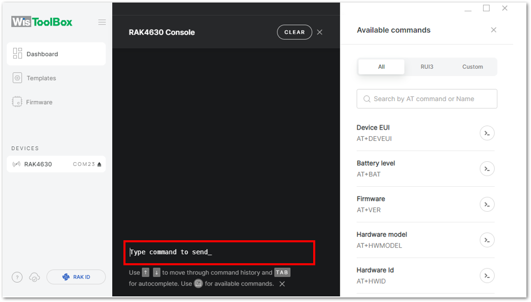 Figure 1: Setting up your Console
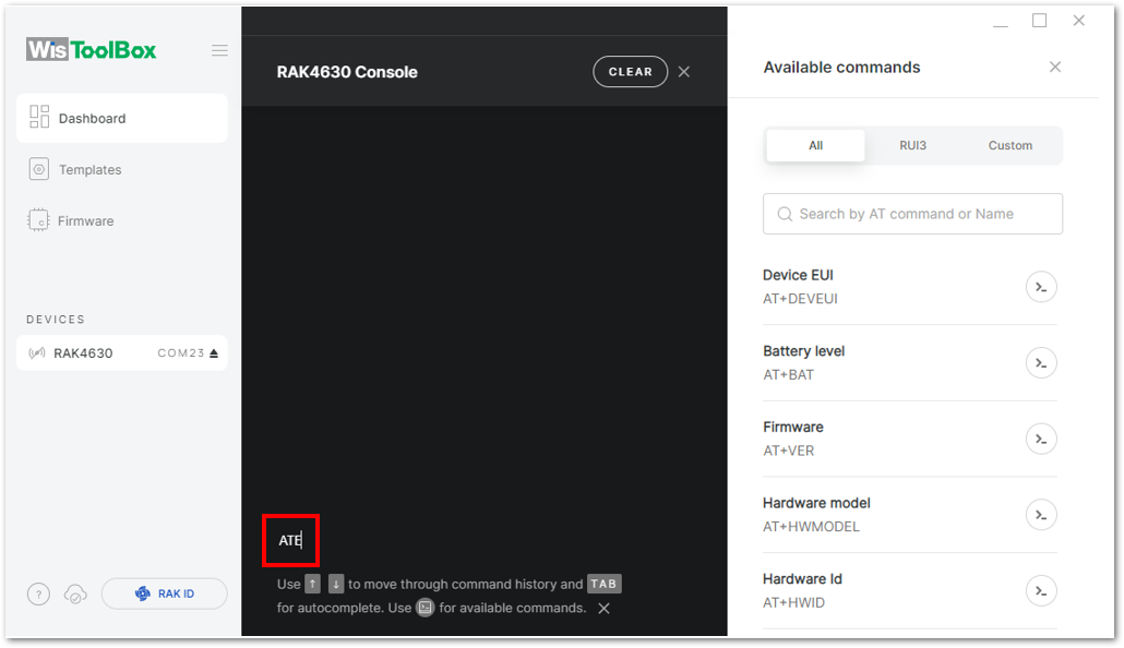 Figure 1: Setting up your Console
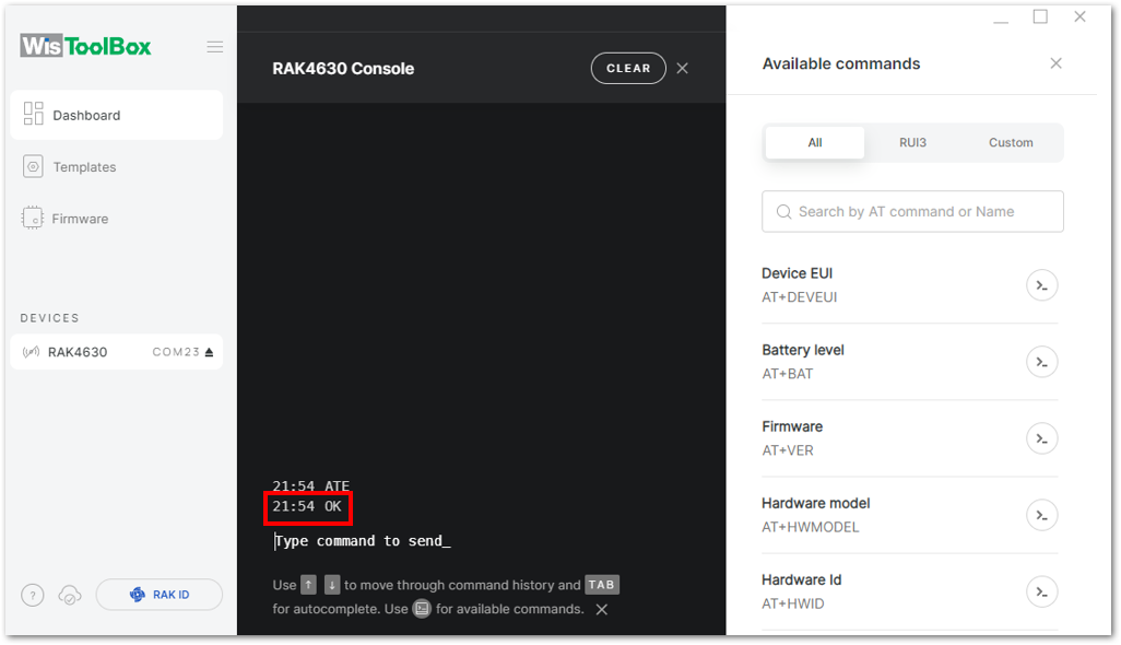 Figure 1: Setting up your Console
- Configure the LoRaWAN join mode to ABP. Check what parameter you will input by typing
AT+NJM?and then Enter into the console terminal. For ABP, inputAT+NJM=0and then press Enter.
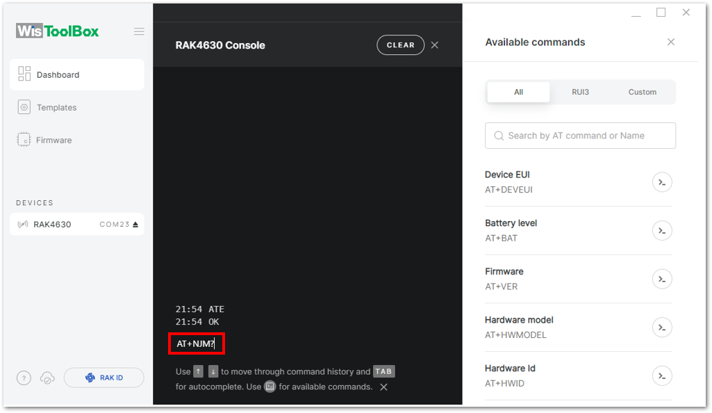 Figure 1: Setting up your Console
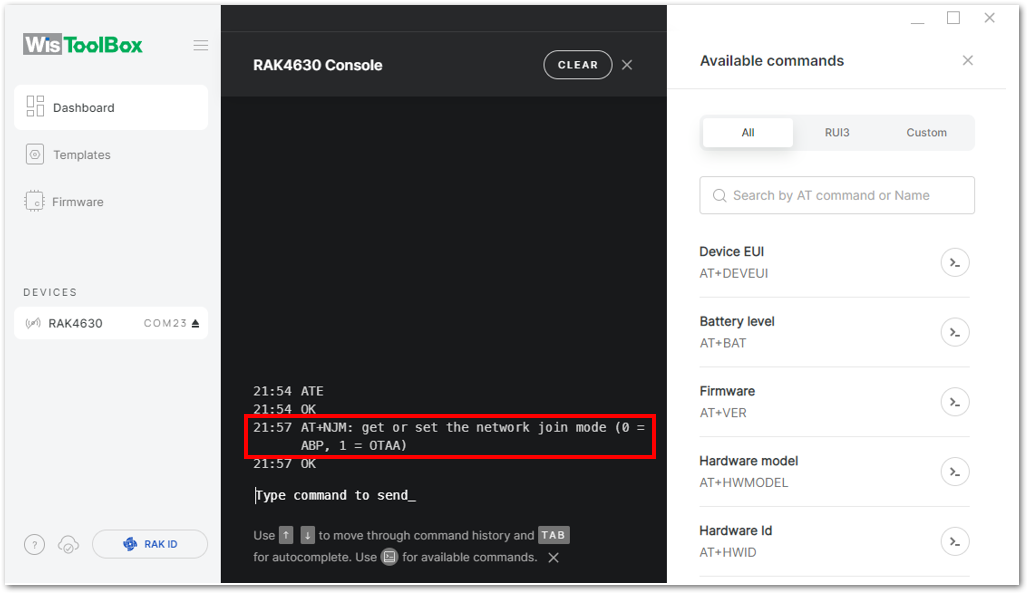 Figure 1: Setting up your Console
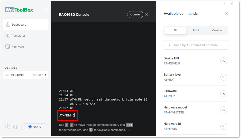 Figure 1: Setting up your Console
- Once done, set up your LoRaWAN region to EU868. Check what parameter you will input by typing AT+BAND? and then Enter into the console terminal. For EU868, input AT+BAND=4 then press Enter. If you wish to work on other regional bands, you may check the List of band parameter options
Set the frequency/region to EU868.
AT+BAND=4
Depending on the Regional Band you selected, you might need to configure the sub-band of your RAK module to match the gateway and LoRaWAN network server. This is especially important for Regional Bands like US915, AU915, and CN470.
To configure the masking of channels for the sub-bands, you can use the AT+MASK command that can be found on the AT Command Manual.
To illustrate, you can use sub-band 2 by sending the command AT+MASK=0002.
-
EU433=0
-
CN470=1
-
RU864=2
-
IN865=3
-
EU868=4
-
US915=5
-
AU915=6
-
KR920=7
-
AS923-1=8
-
AS923-2=9
-
AS923-3=10
-
AS923-4=11
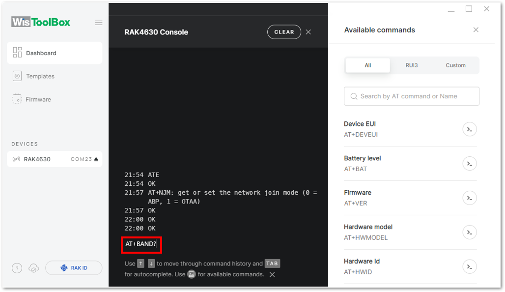 Figure 1: Setting up your Console
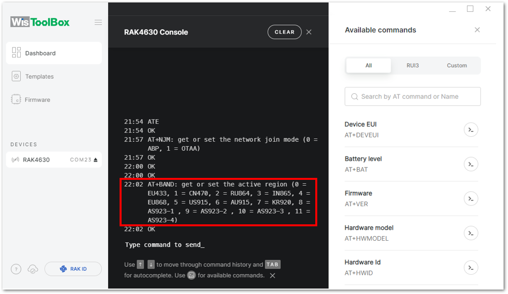 Figure 1: Setting up your Console
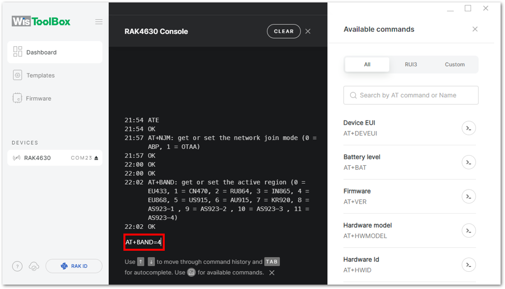 Figure 1: Setting up your Console
- Update the ABP credentials of your device and start with the Application Session Key (AppSKey). Go back to your console where your End device was created to copy the AppSKey credential, then paste it into the WisToolBox Console, and press Enter.
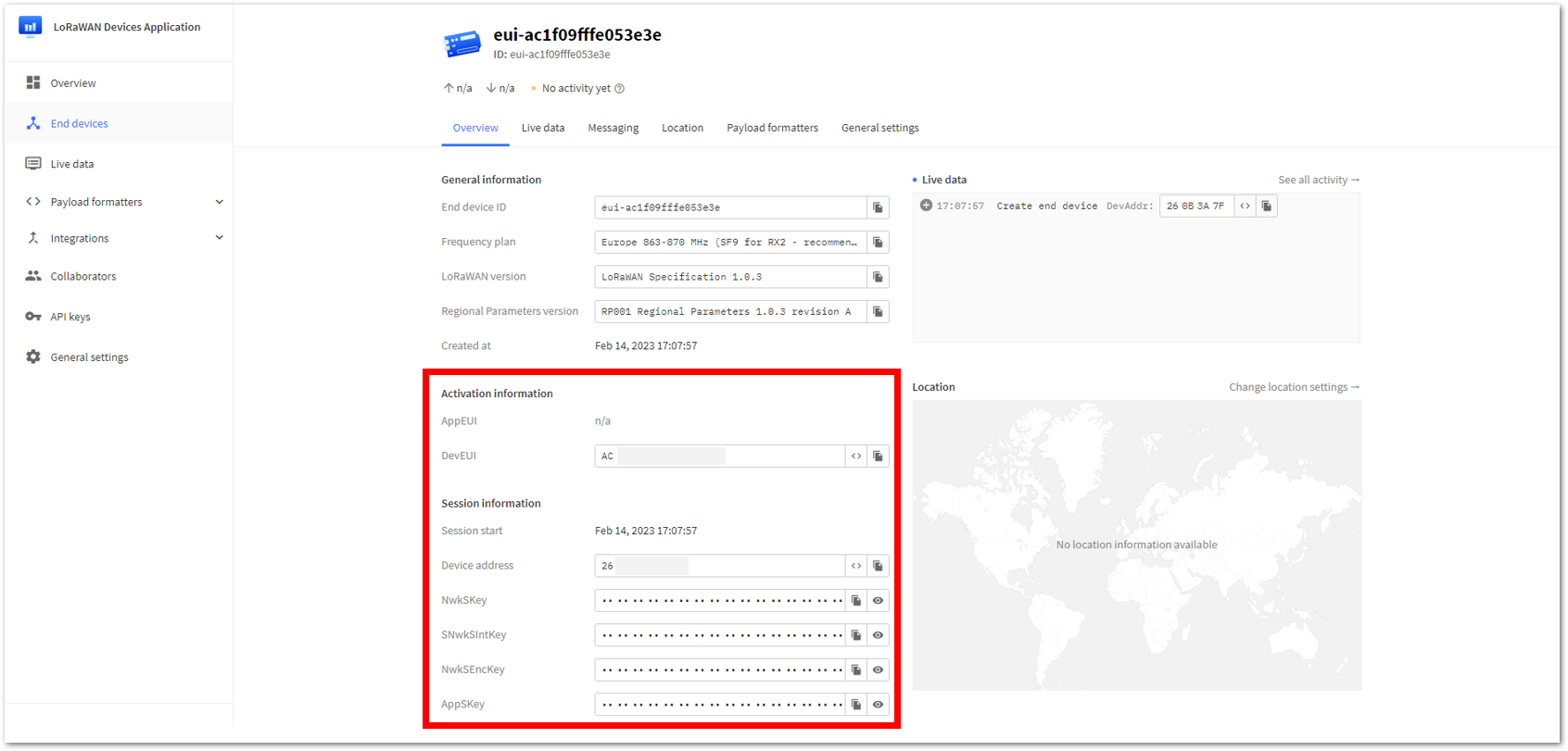 Figure 1: ABP information of the device from your TTN console
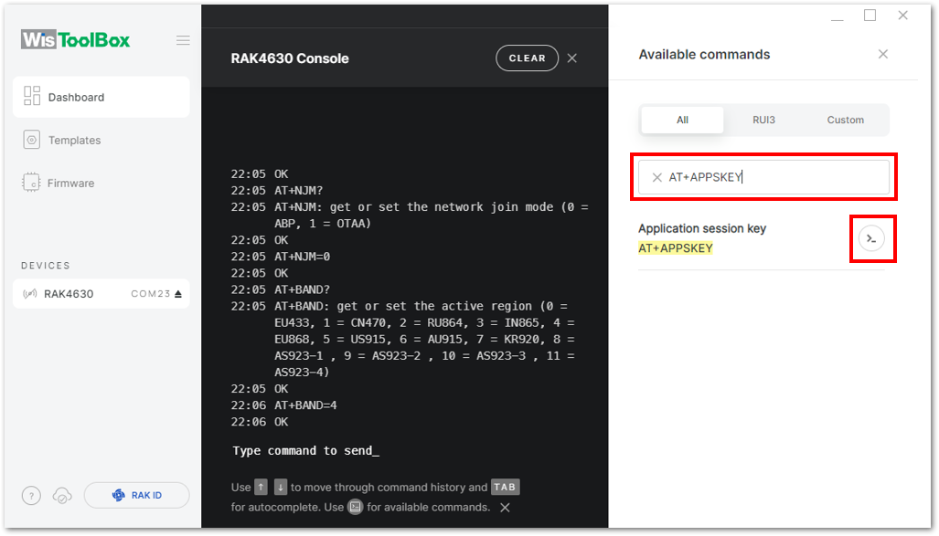 Figure 1: Setting up your Console
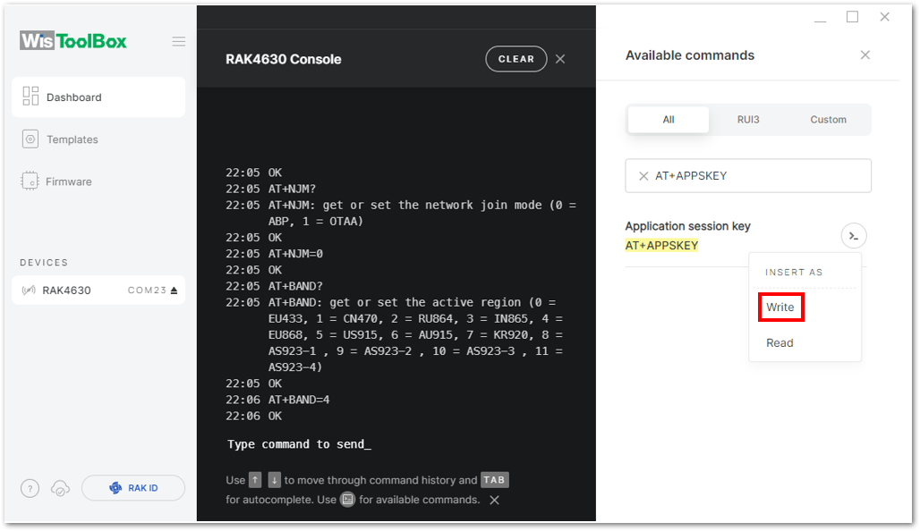 Figure 1: Write the key
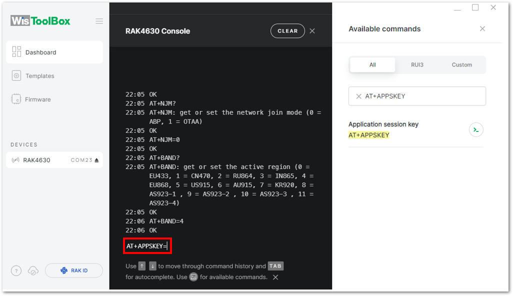 Figure 1: Setting up your Console
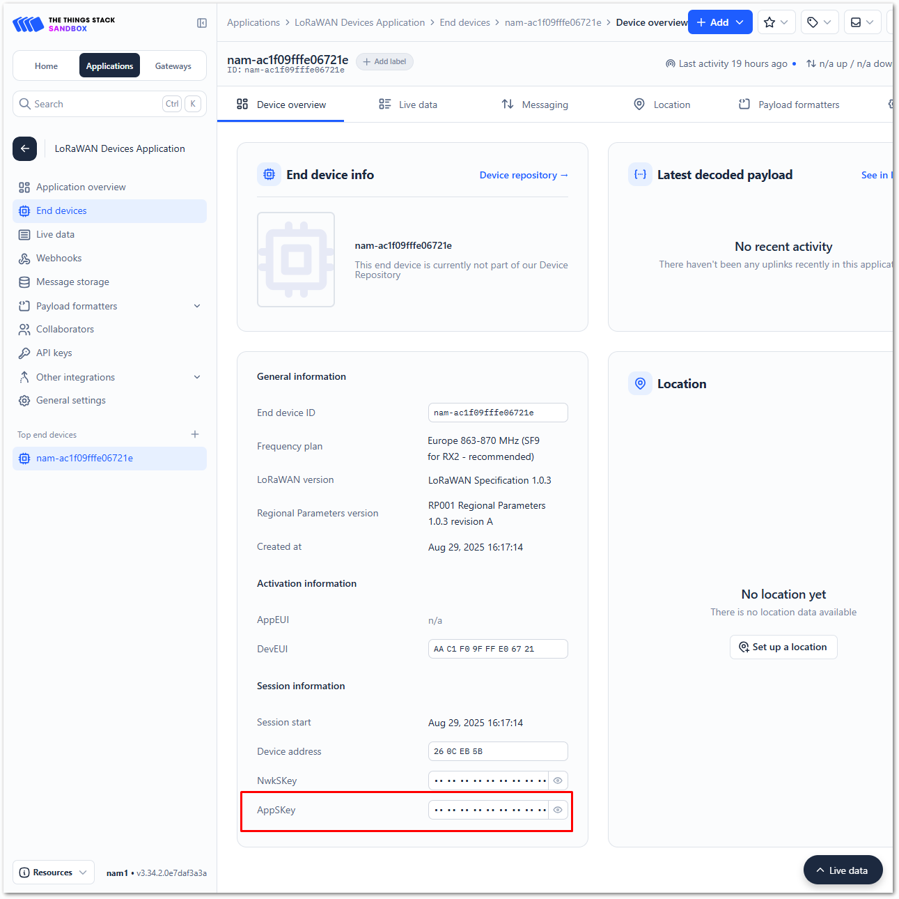 Figure 1: Copying the AppSKey credential from TTN to WisToolBox
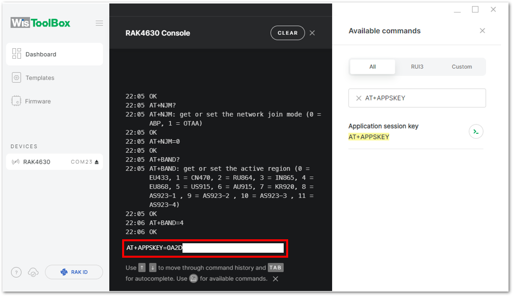 Figure 1: Setting up your Console
- Repeat the same procedure for the Device Address and Network Session Key (NwkSKey).
- For Device address
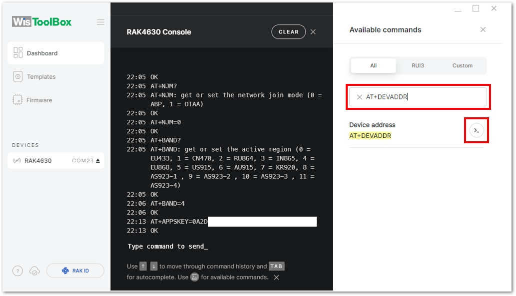 Figure 1: Setting up your Console
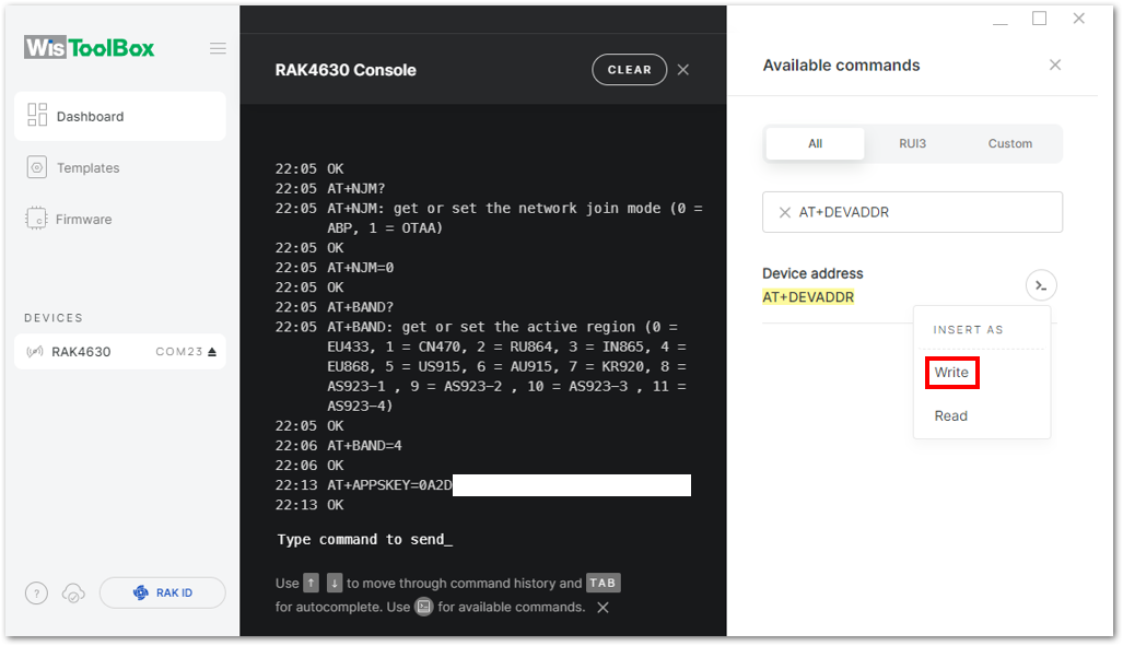 Figure 1: Setting up your Console
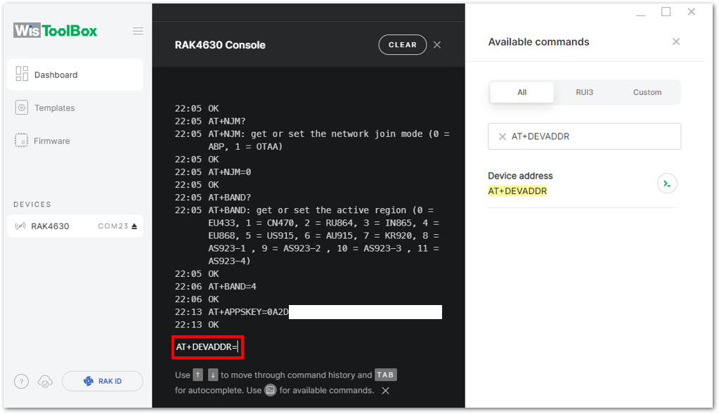 Figure 1: Setting up your Console
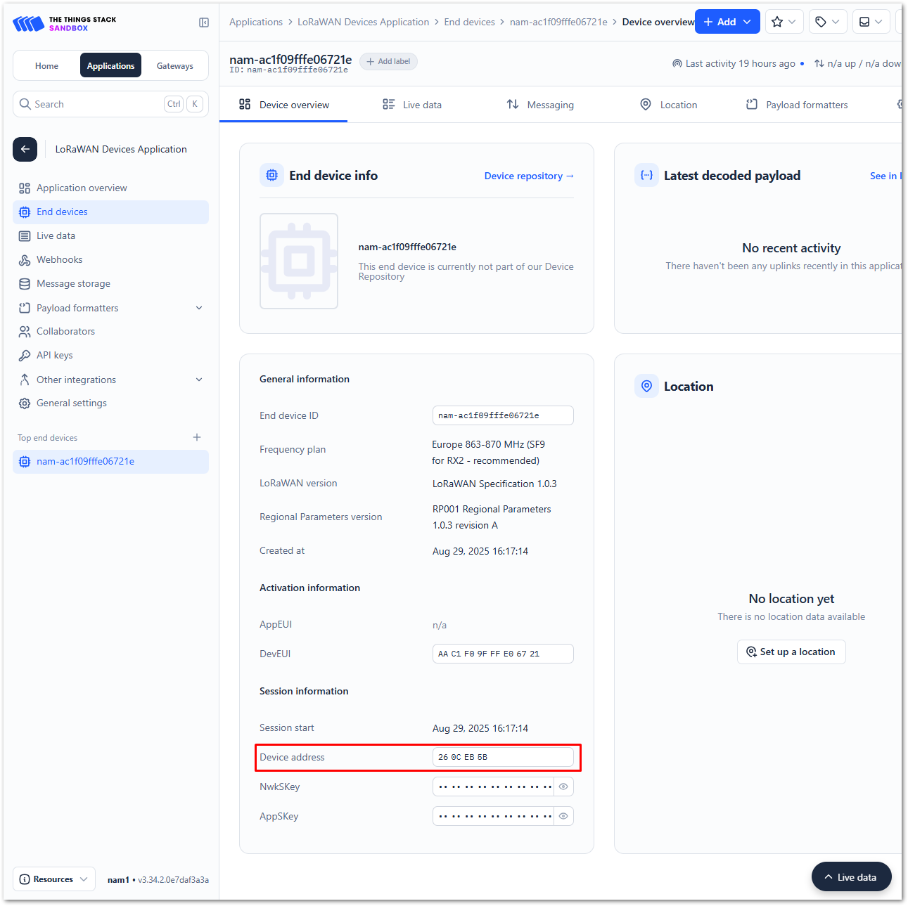 Figure 1: Copying the Device address credential from TTN to WisToolBox
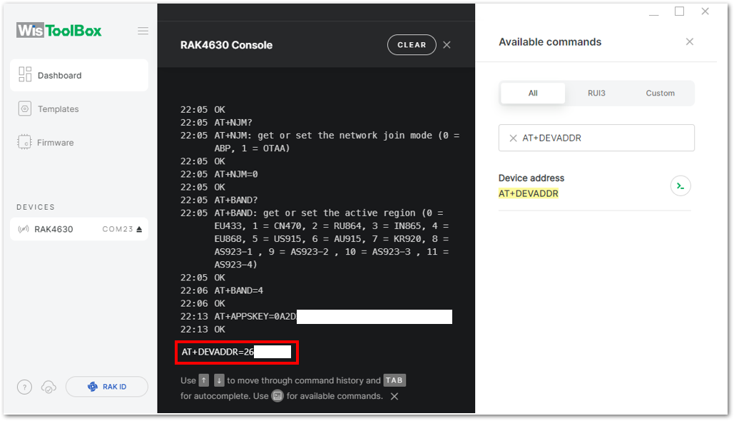 Figure 1: Setting up your Console
- For Network session key (NwkSKey)
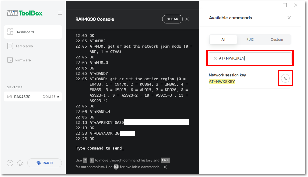 Figure 1: Setting up your Console
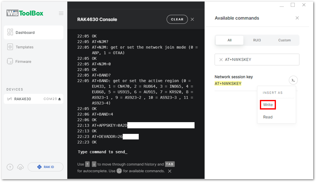 Figure 1: Setting up your Console
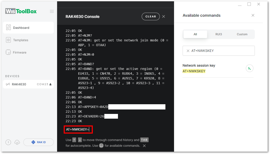 Figure 1: Setting up your Console
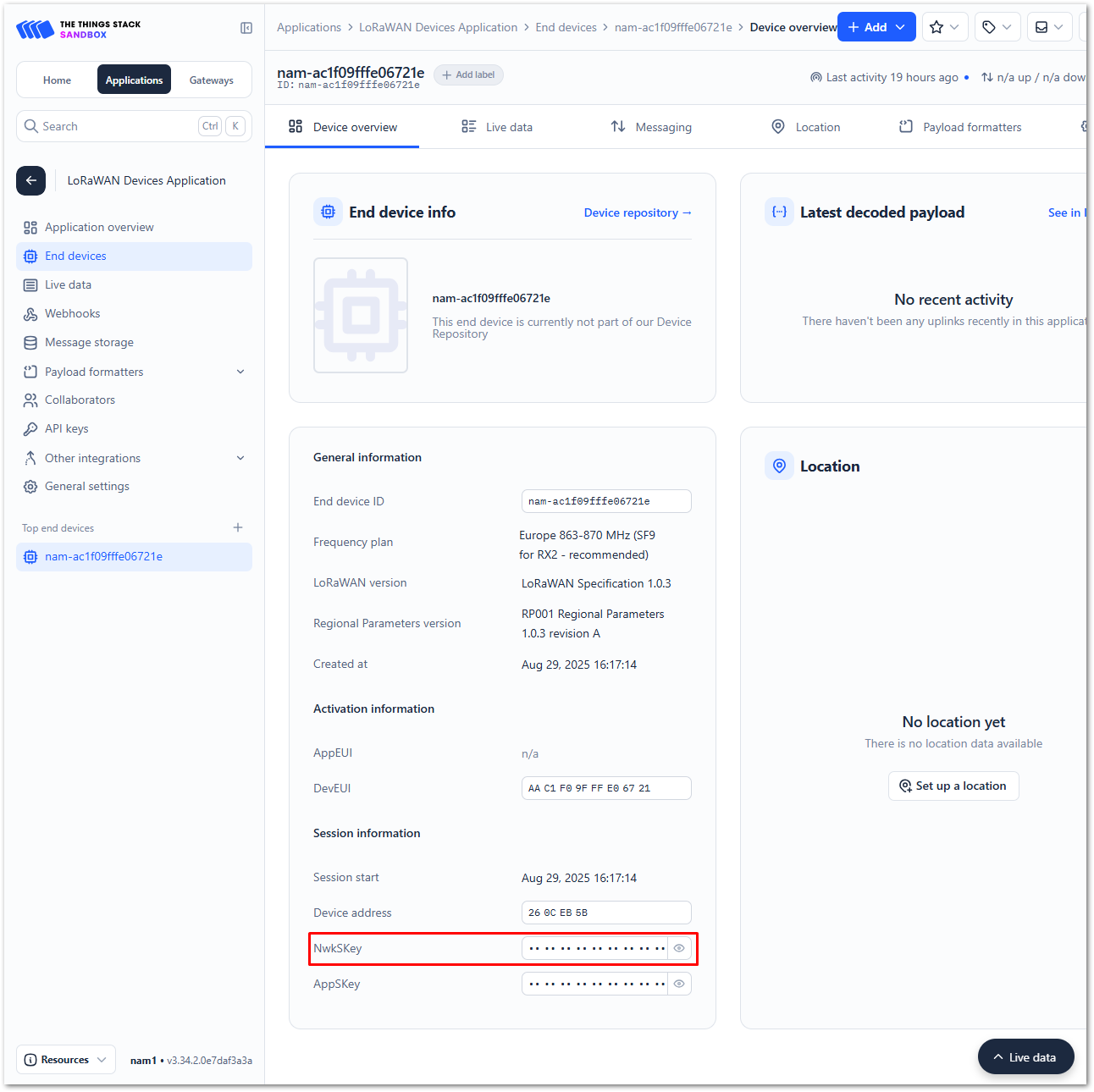 Figure 1: Copying the NwkSKey credential from TTN to WisToolBox
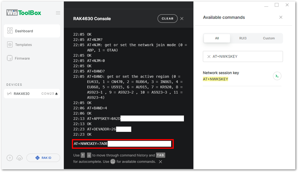 Figure 1: Setting up your Console
- Once completed, click Dashboard to verify the updated credentials of your ABP device. Then, click PARAMETERS to open the Global Settings and LoRaWAN keys, ID, EUI sections to confirm that they have been updated accordingly.
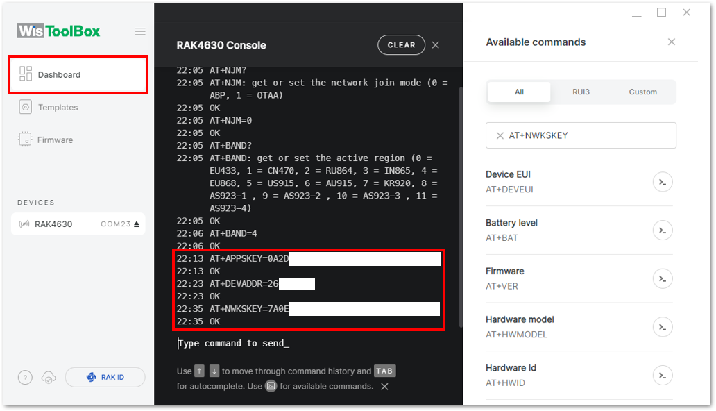 Figure 1: Setting up your Console
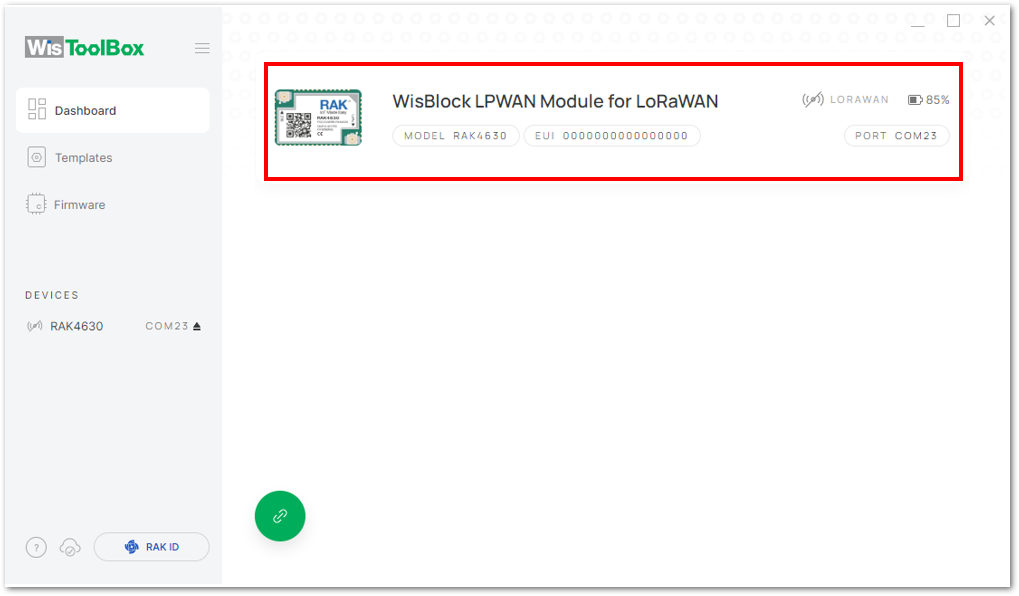 Figure 1: Setting up your Console
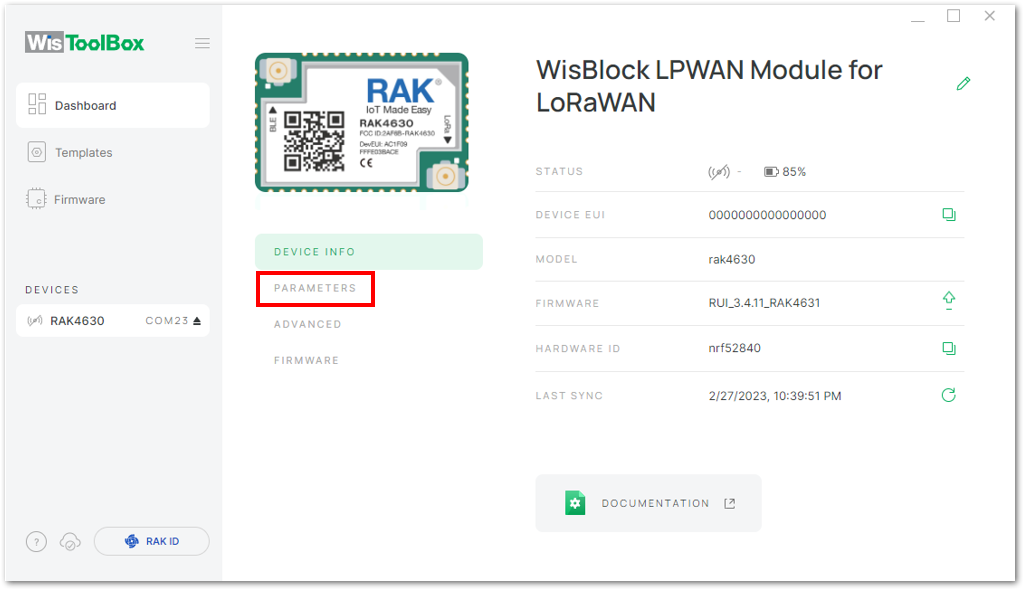 Figure 1: PARAMETERS
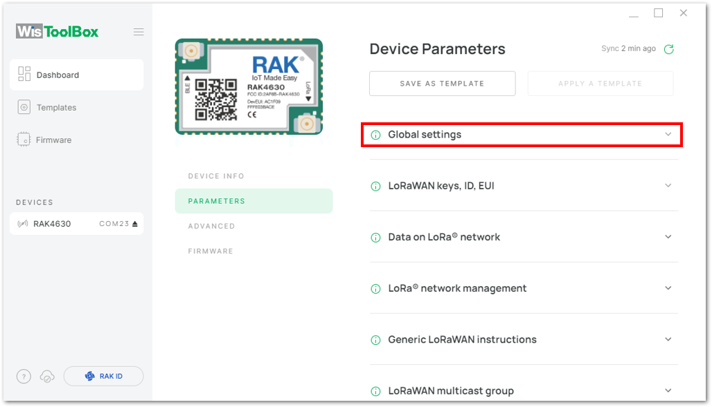 Figure 1: Global settings and LoRaWAN keys, ID, EUI
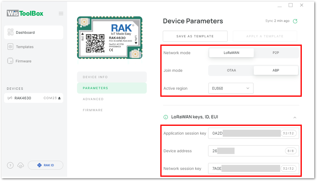 Figure 1: Global settings and LoRaWAN keys, ID, EUI details
Now you have a configured ABP device using WisToolBox Console. ABP-configured devices are directly tied to the network once done with the above procedures so joining procedure is not needed.
- Try sending the payload to TTN. Open again the terminal console of WisToolBox to send some payload. Send the command format:
AT+SEND=<port>:<payload>
AT+SEND=2:12345678
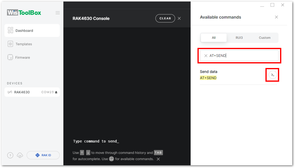 Figure 1: ABP device sending payload to the network
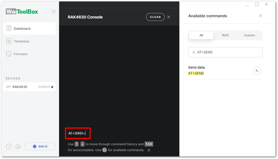 Figure 1: ABP device sending payload to the network
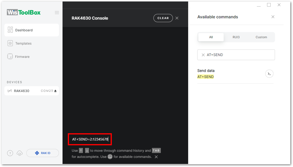 Figure 1: ABP device sending payload to the network
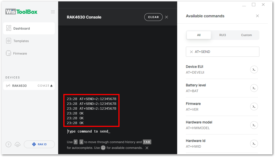 Figure 1: ABP device sending payload to the network
- You can see the data sent by the RAK module on the TTN device console Live data section. Also, the Last seen info should be a few seconds or minutes ago.
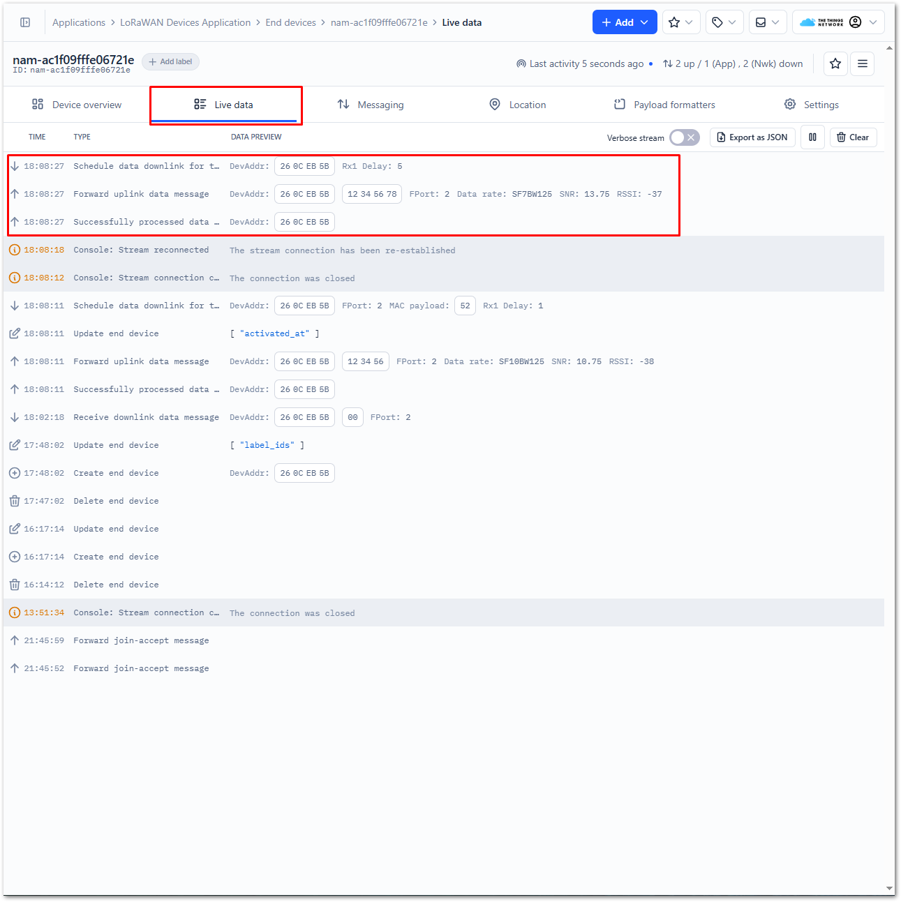 Figure 1: ABP Test Sample Data Sent Viewed in TTN
Connect to ChirpStack
ChirpStack is an open-source LoRaWAN Network Server for managing LoRaWAN devices and applications. Learn more about ChirpStack.
This section covers connecting a RAK Gateway to ChirpStack, registering a WisDUO module, and configuring the module using AT commands.
Figure 1: RAK end device in the context of the ChirpStack platformRegister the LoRaWAN Gateway on ChirpStack
Choose the appropriate guide below to register and connect your RAK Gateway to ChirpStack:
- How to Register a RAK Gateway in Chirpstack V4
- How to Register a RAK Gateway in Chirpstack V3
- How to Connect RAK Gateways to Chirpstack v3 via UDP
- How to Connect RAK Gateways to Chirpstack v4 via UDP
- How to Connect RAK Gateways to Chirpstack v4 via MQTT
- How to Connect RAK Gateway to Chirpstack v3 Using Basics™ Station (LNS)
- How to Connect RAK Gateway to Chirpstack v4 Using Basics™ Station (LNS)
Register the RAK3172-SiP on ChirpStack
Step 1: Create a ChirpStack Application
- Log in to the ChirpStack server using your account and password.
- Go to the Application section.
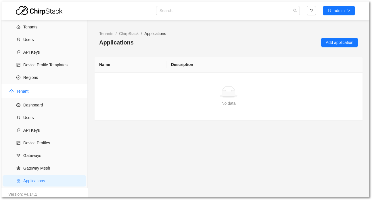 Figure 1: Application section
- By default, you should create a new application, although you can reuse existing ones. For this setup, create a new Application by clicking on the CREATE button and filling in the required parameters.
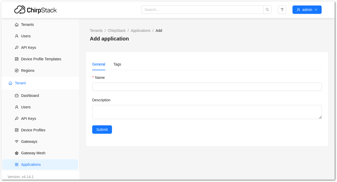 Figure 1: Creating a new application
For this example, create an Application named rak_node_test.
ChirpStack supports multiple system configurations, although only one is enabled by default.
- Service profile: This field allows you to select the system profile.
- Payload codec: This field determines the parsing method for payload data, such as parsing LPP format data.
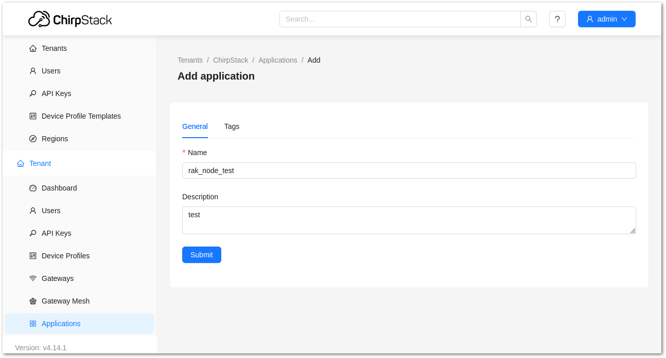 Figure 1: Filling in the parameters of an application
Step2: Register an End Device
- Choose the Application created in the previous step, then select the DEVICES tab.
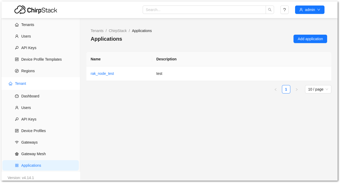 Figure 1: List of applications created
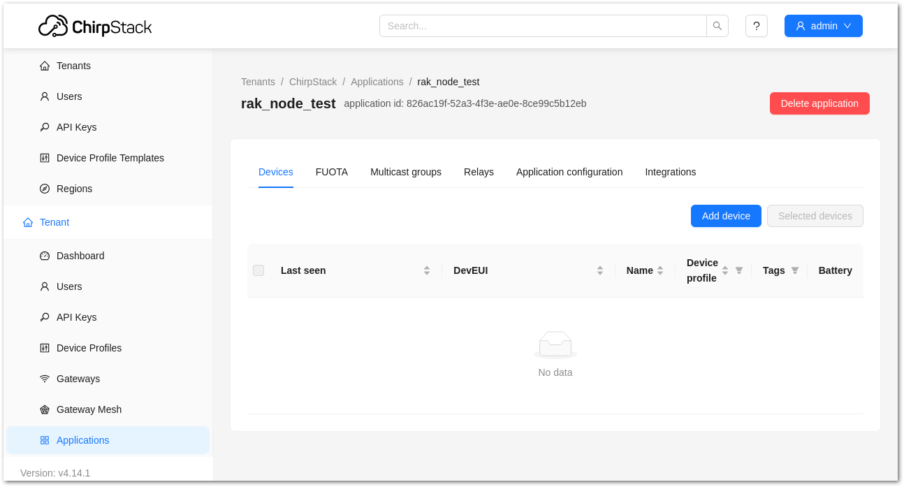 Figure 1: Device tab of an application
- Inside the DEVICE tab, create a new device (LoRaWAN node) by clicking on the + CREATE button.
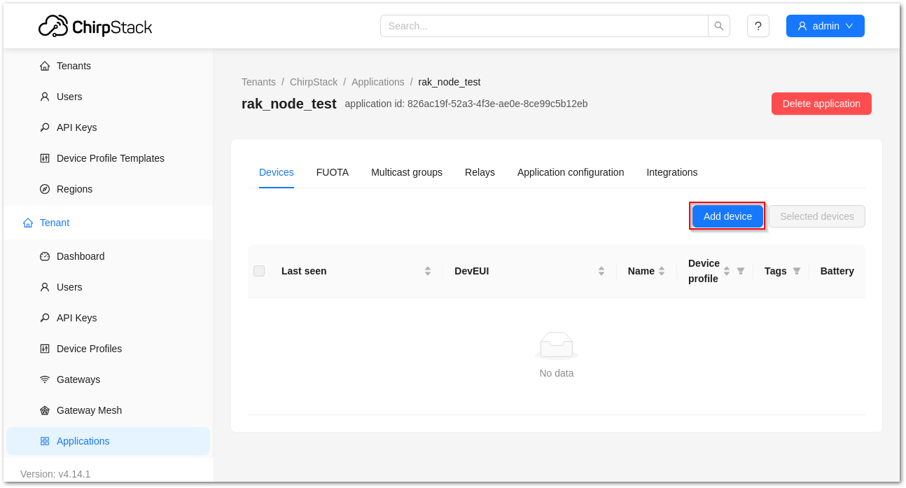 Figure 1: Add a new device
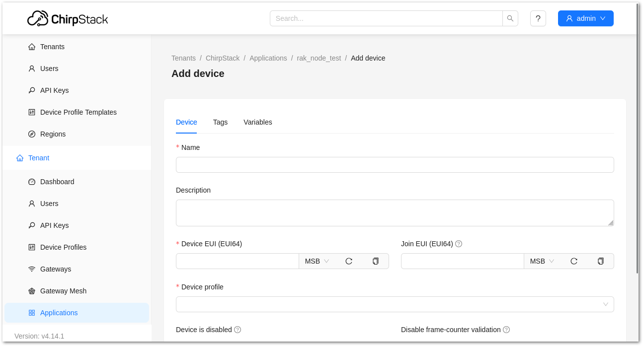 Figure 1: Chirpstack adding node into the RAK end device
- Once the node is created, fill in the necessary data. You can generate a Device EUI automatically by clicking the load icon, or you can manually enter the correct Device EUI in the edit box.
Fill in the parameters requested:
- Device name and Device description: These are descriptive texts about your device.
- Device EUI: This interface allows you to generate a Device EUI automatically by clicking the generate icon. You can also add a specific Device EUI directly in the form.
- Device Profile:
- If you want to join in OTAA mode, select DeviceProfile_OTAA.
- If you want to join in ABP mode, select DeviceProfile_ABP.
Device profiles DeviceProfile_OTAA and DeviceProfile_ABP are only available if you are using the built-in ChirpStack LoRaWAN Server of RAK Gateways.
If you have your own Chirpstack installation, set up the device profile with LoRaWAN MAC version 1.0.4 and LoRaWAN Regional Parameters revision B to make it compatible with RAK end device.
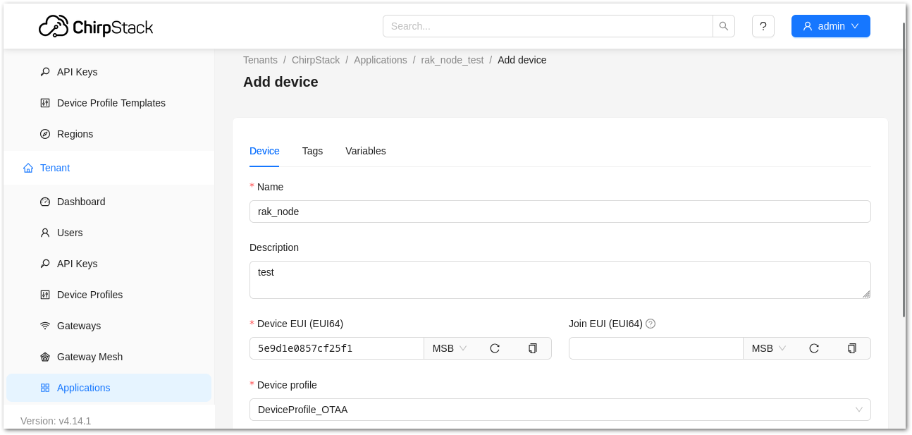 Figure 1: Generate a new Device EUI
Step 3: Configure Device Credentials
After registering the module on ChirpStack, configure the corresponding credentials according to the selected activation method, as described in the following sections.
OTAA Device
- If you selected DeviceProfile_OTAA during device registration, configure the Application Key for the device.
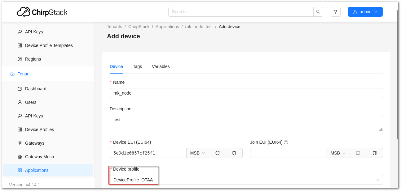 Figure 1: Chirpstack OTAA activation
- The previously created Application Key can be entered here, or a new one can be generated automatically by clicking the Refresh icon.
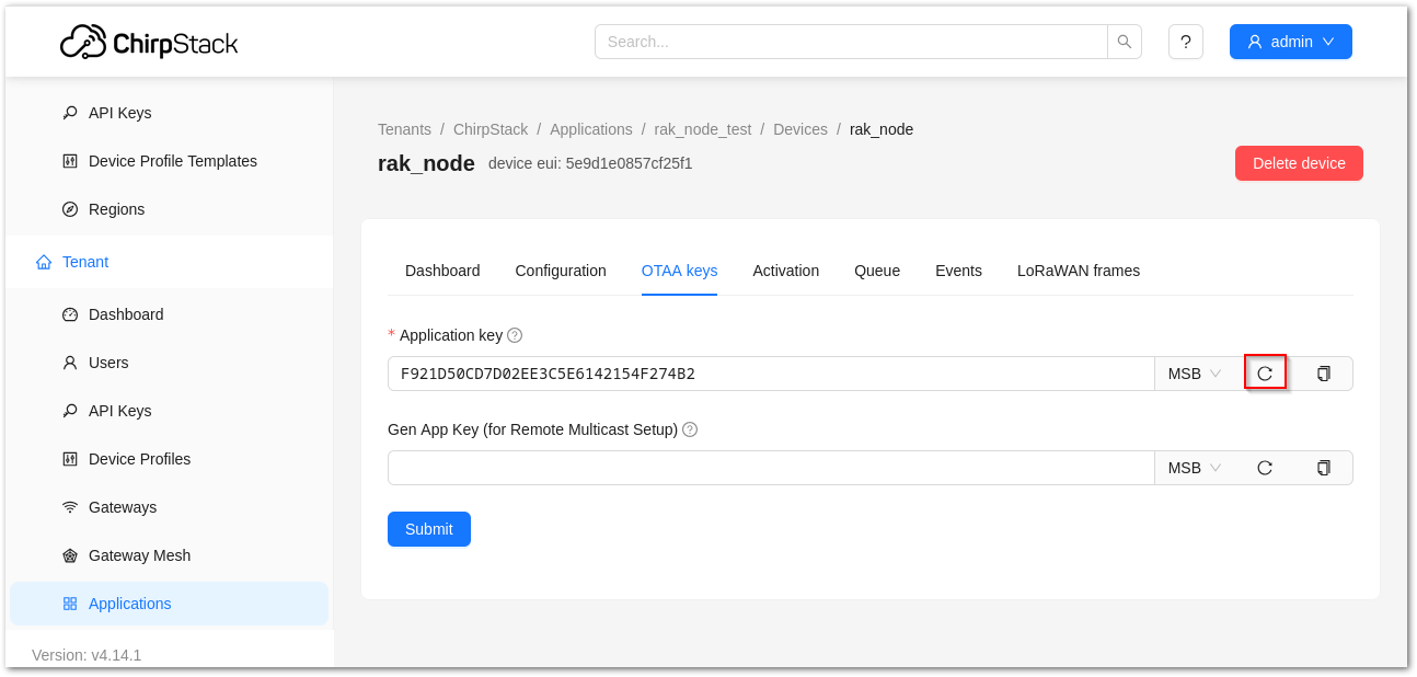 Figure 1: Chirpstack OTAA Set Application Keys
- Once the Application Key is added to the form, the process can be finalized by clicking on the SET DEVICE-KEYS button. A new device should be listed in the DEVICES tab. The most important parameters, such as the Device EUI, are shown in the summary.
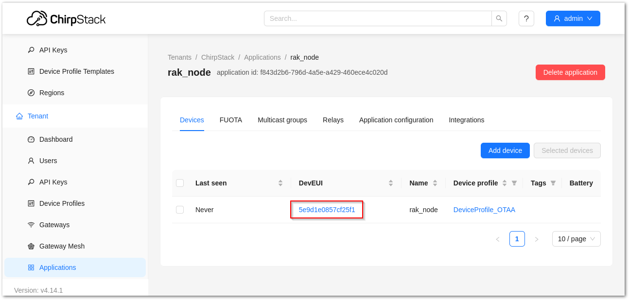 Figure 1: Chirpstack OTAA list of the device in the Device Tab
- To end the process, it is a good practice to review that the Application Key is properly associated with this device. The Application Key can be verified in the KEYS(OTAA) tab.
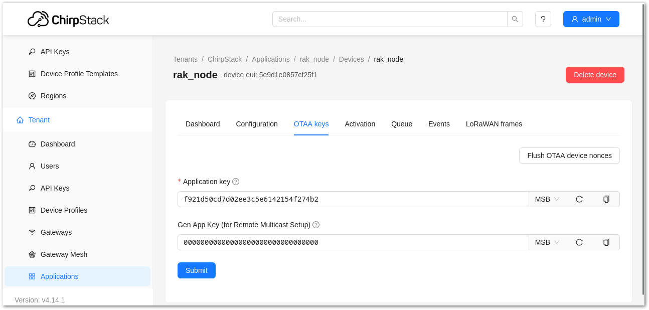 Figure 1: Application key associated with the new device
Standard OTAA mode requires the Device EUI, Application Key, and Application EUI, but in ChirpStack’s implementation, only the Device EUI and the Application Key are mandatory. The Application EUI is not required and not recorded in the Application tab. Nevertheless, you can reuse the Device EUI as the Application EUI during the configuration on the side of the node.
ABP Device
- If you select DeviceProfile_ABP during device registration, the ChirpStack platform will assume that this device will join the LoRaWAN network using the ABP mode.
Check Disable counting frame verification. During testing, if the module is restarted, the frame counting number will also be reset to zero. This can lead to synchronization issues with the ChirpStack server, which may interpret it as a replay attack. While it's safe to disable this feature for testing purposes, remember to activate it in a production environment.
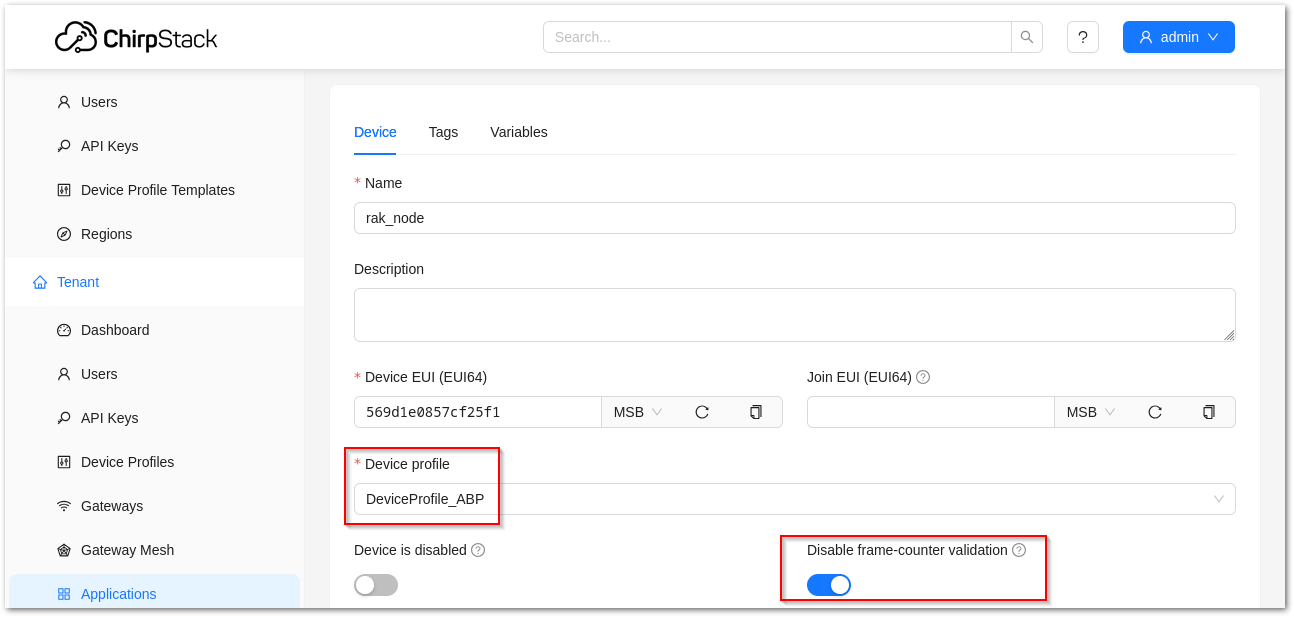 Figure 1: ChirpStack console, configuring a device
-
After selecting the ABP mode, the following parameters appear in the Activation tab:
-
Device Address
-
Network Session Key
-
Application Session Key
-
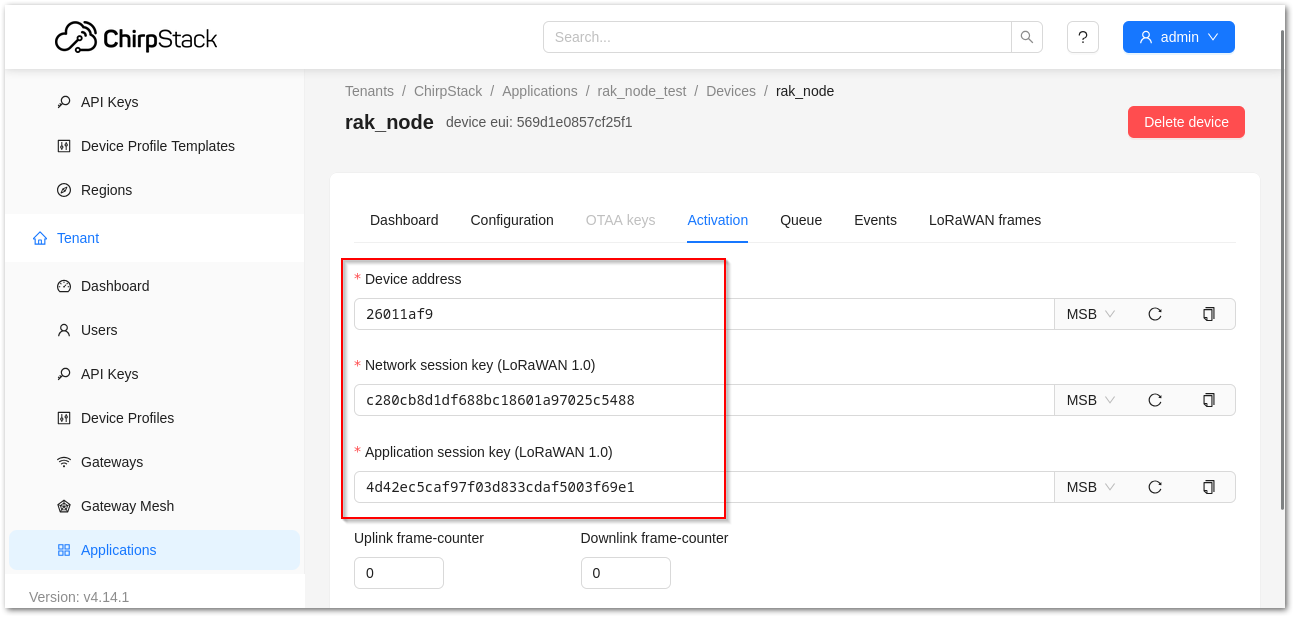 Figure 1: Chirpstack ABP activation parameters needed
- The parameters can either be generated as random numbers by the platform or set with user-defined values. Once these parameters are filled in correctly, the process is completed by clicking on the ACTIVATE DEVICE button.
After registering the device on ChirpStack, choose the configuration method that matches your activation mode.
OTAA Configuration for ChirpStack
- Open the Serial terminal like the RAK Serial Port Tool. Select the right COM port and set the baud rate to 115200.
It is recommended to start by testing the serial communication and verify that the current configuration is working by sending these two AT commands:
AT
ATE
ATE will echo the commands you input to the module, which is useful for tracking the commands and troubleshooting.
You will receive OK when you input the two commands. After setting ATE, see all the commands you input together with the replies. Try again AT and you should see it on the terminal followed by OK.
If you haven't received an OK or any reply, you need to check if the wiring of your UART lines is correct and if the baud is correctly configured to 115200. Also, you can check if the device is powered correctly. If you are getting power from a USB port, ensure that you have a good USB cable.
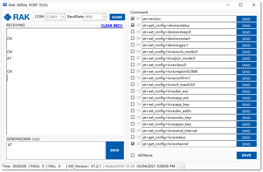 Figure 1: at+version command response
- The next step is to configure the OTAA LoRaWAN parameters in the module:
Set the work mode to LoRaWAN. You might need to reconnect on the Serial Terminal Software Tool if you lost connection after using the AT+NWM=1 command.
AT+NWM=1
Set the LoRaWAN activation to OTAA.
AT+NJM=1
Set the LoRaWAN class to Class A.
AT+CLASS=A
Set the frequency/region to EU868.
AT+BAND=4
Depending on the Regional Band you selected, you might need to configure the sub-band of your RAK end device to match the gateway and LoRaWAN network server. This is especially important for Regional Bands like US915, AU915, and CN470.
To configure the masking of channels for the sub-bands, you can use the AT+MASK command that can be found on the AT Command Manual.
To illustrate, you can use sub-band 2 by sending the command AT+MASK=0002.
List of band parameter options
| Code | Regional Band |
|---|---|
| 0 | EU433 |
| 1 | CN470 |
| 2 | RU864 |
| 3 | IN865 |
| 4 | EU868 |
| 5 | US915 |
| 6 | AU915 |
| 7 | KR920 |
| 8 | AS923 |
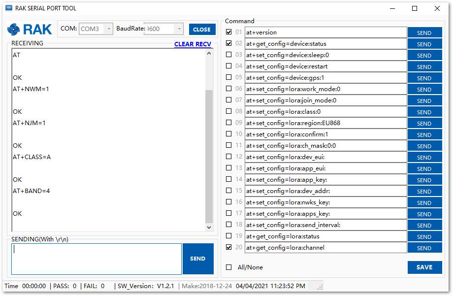 Figure 1: Configuring LoRa parameters
- Set up the EUIs and key. You need to use the values from the TTN console you configured in the earlier steps, the values shown are examples.
The Application EUI parameter is not required in the ChirpStack platform; therefore, it is possible to use the same id as the Device EUI.
Set the Device EUI.
AT+DEVEUI=5E9D1E0857CF25F1
Set the Application EUI.
AT+APPEUI=5E9D1E0857CF25F1
Set the Application Key.
AT+APPKEY=F921D50CD7D02EE3C5E6142154F274B2
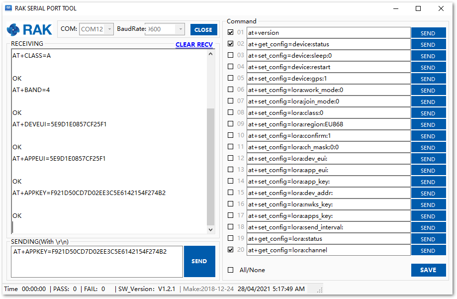 Figure 1: Configuring LoRa Parameters
- After the EUI and key configuration, the device can now join the network and send some payload. Join command format:
AT+JOIN=w:x:y:z
AT+JOIN=1:0:10:8
| Parameter | Description |
|---|---|
| w | Join command - 1: joining, 0: stop joining. |
| x | Auto-join config - 1: auto-join on power-up, 0: no auto-join |
| y | Reattempt interval in seconds (7-255) - 8 is the default. |
| z | Number of join attempts (0-255) - 0 is default. |
After 5 or 6 seconds, if the request is successfully received by a LoRa gateway, you should see the JOINED status reply.
If the OTAA device failed to join, check if your device is within reach of a working LoRaWAN gateway that is configured to connect to Chirpstack. It is also important to check that all your OTAA parameters (DEVEUI and APPKEY) are correct, using the AT+DEVEUI=? and AT+APPKEY=? commands. Lastly, ensure that the antenna of your device is properly connected.
After checking all the things above, try to join again.
- With the end-device properly activated, try to send some payload after a successful join. Send command format:
AT+SEND=<port>:<payload>
AT+SEND=2:12345678
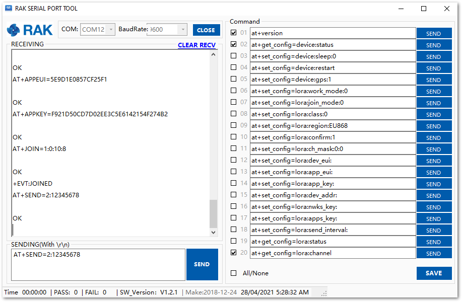 Figure 1: OTAA test sample data sent via RAK Serial Port Tool
On the ChirpStack platform, you should see the join and uplink messages in the LORAWAN FRAMES tab. By convention, messages sent from nodes to gateways are considered as Uplinks while messages sent by gateways to nodes are considered as Downlinks.
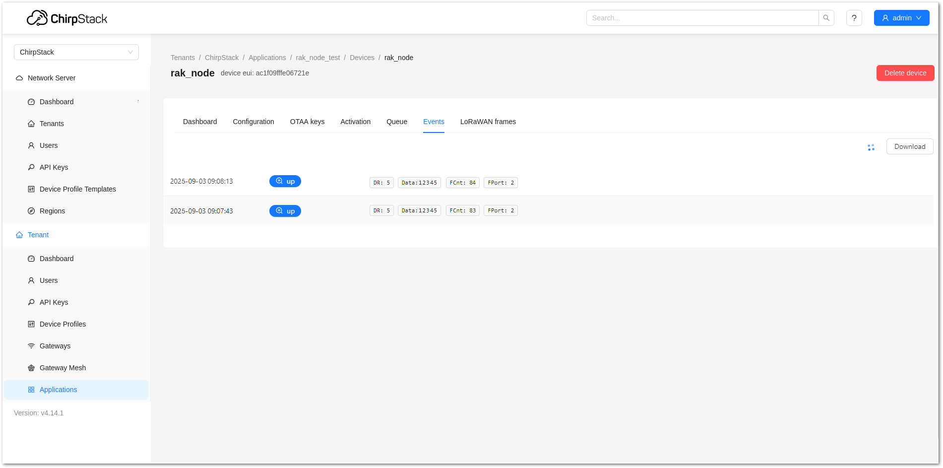 Figure 1: Chirpstack data received preview
ABP Configuration for ChirpStack
-
Open the RAK Serial Port Tool. Select the right COM port and set the baud rate to 115200.
-
The next step is to configure the ABP LoRaWAN parameters in RAK end device:
Set the work mode to LoRaWAN. You might need to reconnect on the Serial Terminal Software Tool if you lost connection after using the AT+NWM=1 command.
AT+NWM=1
Set the LoRaWAN activation to ABP.
AT+NJM=0
Set the LoRaWAN class to Class A.
AT+CLASS=A
Set the frequency/region to EU868.
AT+BAND=4
Depending on the Regional Band you selected, you might need to configure the sub-band of your RAK end device to match the gateway and LoRaWAN network server. This is especially important on Regional Bands like US915, AU915, and CN470.
To configure the masking of channels for the sub-bands, you can use the AT+MASK command that can be found on the AT Commands Manual.
To illustrate, you can use sub-band 2 by sending the command AT+MASK=0002.
List of band parameter options
| Code | Regional Band |
|---|---|
| 0 | EU433 |
| 1 | CN470 |
| 2 | RU864 |
| 3 | IN865 |
| 4 | EU868 |
| 5 | US915 |
| 6 | AU915 |
| 7 | KR920 |
| 8 | AS923 |
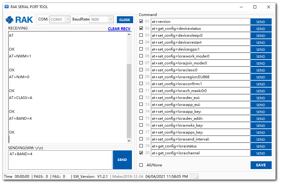 Figure 1: Configuring LoRa parameters
- After the configuration of the LoRaWAN parameters, the next step is to set up the device address and session keys. Use the values from the Chirpstack device console.
Set the Device Address.
AT+DEVADDR=26011AF9
Set the Application Session Key.
AT+APPSKEY=4D42EC5CAF97F03D833CDAf5003F69E1
Set the Network Session Key.
AT+NWKSKEY=C280CB8D1DF688BC18601A97025C5488
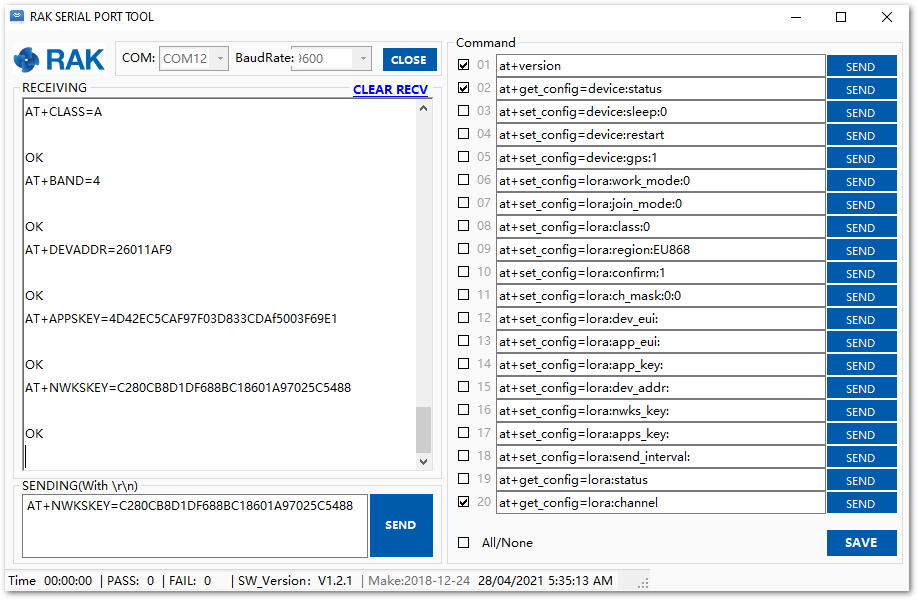 Figure 1: Configuring LoRa parameters
After the EUI and keys configuration, the device can now join the network and send some payload.
AT+JOIN=1:0:10:8
Join command format: AT+JOIN=w:x:y:z
| Parameter | Description |
|---|---|
| w | Join command - 1: joining, 0: stop joining. |
| x | Auto-join config - 1: auto-join on power-up, 0: no auto-join |
| y | Reattempt interval in seconds (7-255) - 8 is the default. |
| z | Number of join attempts (0-255) - 0 is default. |
-
After 5 or 6 seconds, if the request is successfully received by a LoRa gateway, you should see the JOINED status reply.
-
You can now try to send some payload after a successful join. Send command format:
AT+SEND=<port>:<payload>
AT+SEND=2:12341234
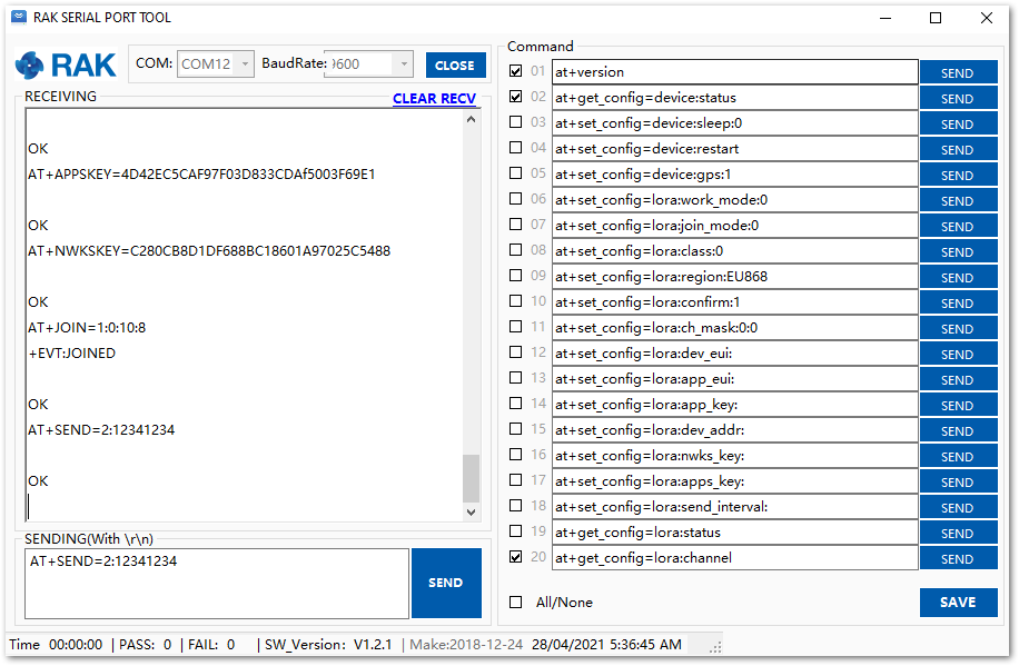 Figure 1: ABP test sample data sent via RAK Serial Port Tool


