RAK7243C Quick Start Guide
Prerequisites
What Do You Need?
- RAK7243C WisGate Developer D3+ Gateway
- 16 GB SD Card + Card Reader
- 5 V at least 3 A Micro USB Power Supply
- A Windows/Mac OS/Linux Computer
- Latest RAK7243C Firmware
The SIM card slot of the cellular versions is not hot-swappable. Make sure the gateway is switched off before inserting or ejecting the SIM card.
What's Included in the Package?
 Figure 1: RAK7243C WisGate Developer D3+ Gateway Package Contents
Product Configuration
Accessing Your Gateway
After burning the firmware image onto the SD Card, make sure you have inserted the SD Card into the RAK7243C WisGate Developer D3+ Gateway and have the LoRa, GPS, and LTE Antenna connected. To learn more on how to burn the image, check the Learn section.
After which, you can now safely power on the gateway. In this section, several ways to access the gateway are provided to have different alternatives for you to choose from depending on the availability of the requirements needed.
::: warning Before powering the Raspberry Pi 3B+, you should connect the LoRa, GPS, and LTE antennas. Not doing so might damage the boards. :::
Wi-Fi AP Mode
By default, the gateway will work in Wi-Fi AP Mode which means that you can find an SSID named Rakwireless_XXXX on your PC Wi-Fi Network List.
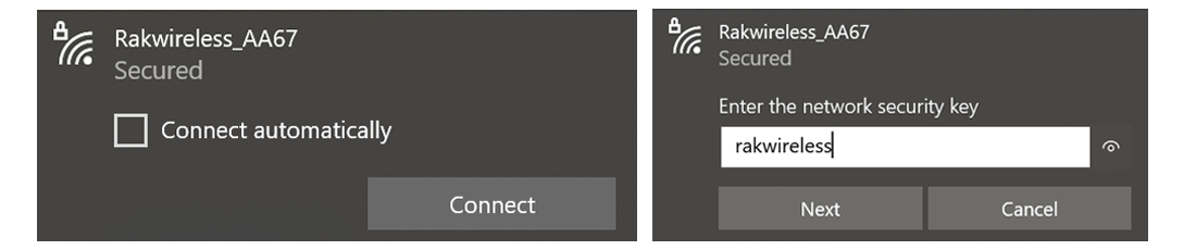 Figure 1: RAKwireless access point
XXXX is the last 2 bytes of your RAK7243C Wi-Fi MAC address. Connect to this Wi-Fi SSID using the password provided below. Take note also of the default IP address of the gateway provided below as this will be needed in connecting via SSH.
- Wi-Fi Password: rakwireless
- Default IP Address:
192.168.230.1
Raspberry Pi 3B+ Ethernet Port
You can also connect your PC with the gateway through an Ethernet cable. By default, the IP address of the gateway’s Ethernet interface is 192.168.10.10, so you need to set the IP address of your PC’s Ethernet to the same network segment, for example, 192.168.10.20.
- To do this on a Windows PC, go to Control Panel -> Network and Internet -> Network and Sharing Center and click on Ethernet.
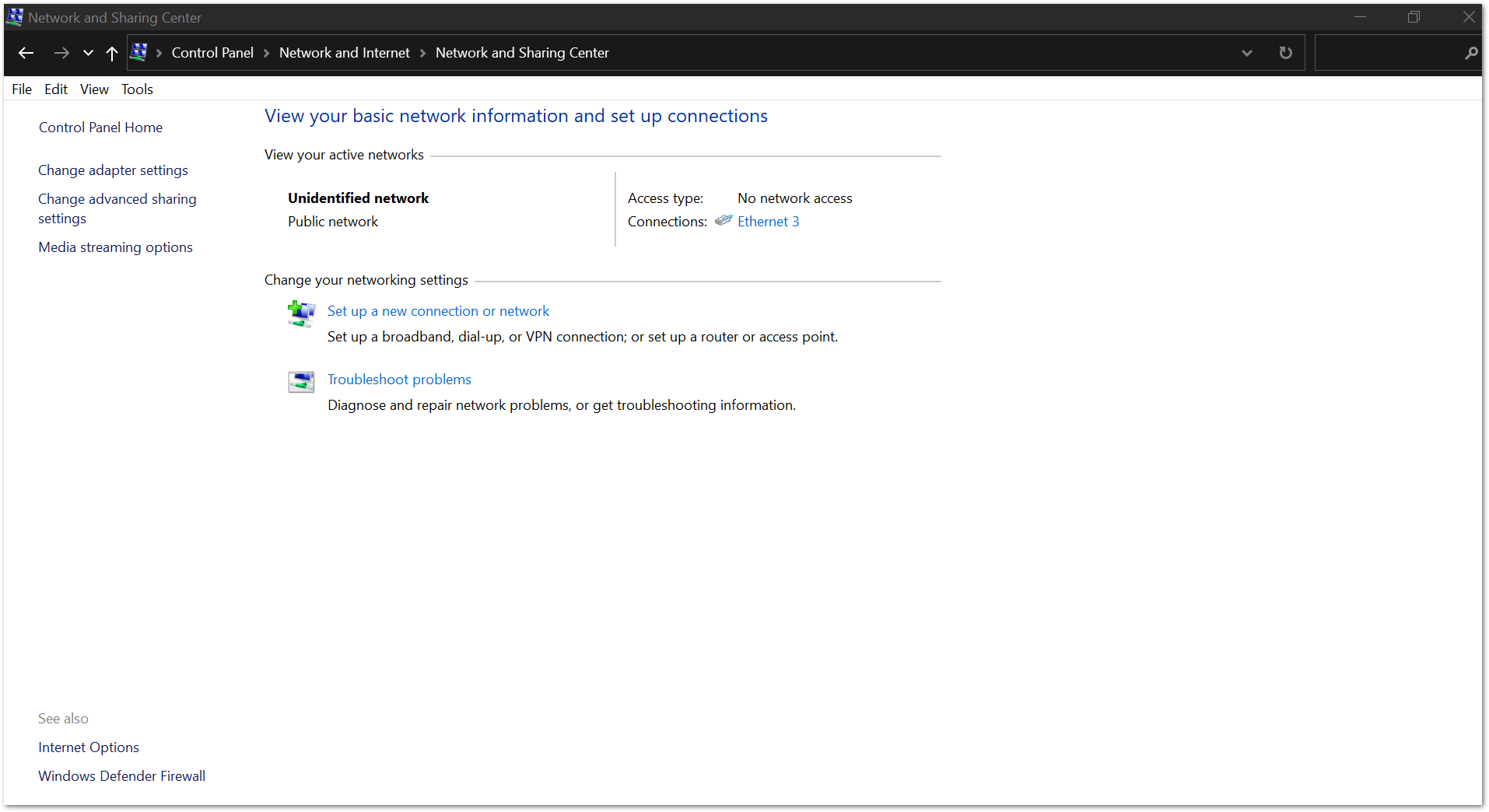 Figure 1: Network and sharing center
- Click Properties then Choose Internet Protocol Version 4 (TCP/IPv4).
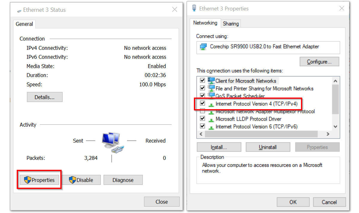 Figure 1: Ethernet properties
- By default, the PC will obtain an IP address automatically. Click Option Use the following IP Address and enter the IP address
192.168.0.10.20, then press OK.
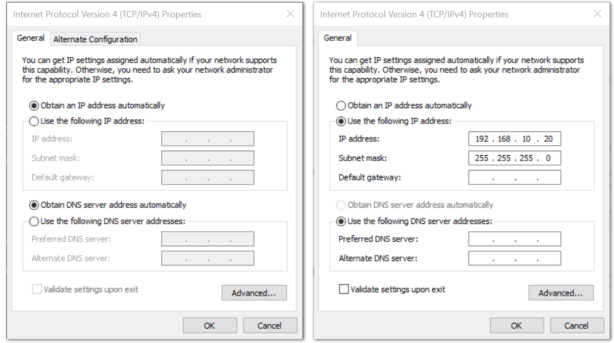 Figure 1: TCP/IPv4 properties
Now, you should be able to access your gateway from your PC successfully using the IP address 192.168.10.10 through SSH.
Log in to the Gateway
Windows OS
SSH (Secure Shell) is typically used to log in to a remote machine and execute commands. There are a lot of free and good SSH Clients out there namely Putty, BitVise SSH Client, MobaXterm and many more. Feel free to choose one that fits your needs. But for this guide, you will be using Putty.
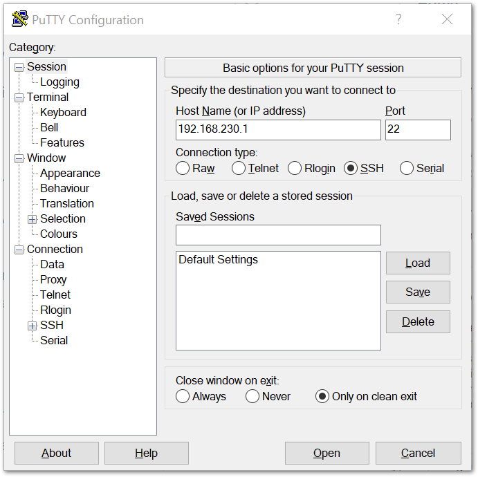 Figure 1: Putty Software for SSH in Windows
- If you have connected to the gateway through Wi-Fi AP Mode, the IP Address is
192.168.230.1 - If you have connected to the gateway through Ethernet, the IP Address is
192.168.10.10 - It will then prompt you to enter the username and password. The default username and password are provided below:
- Username: pi
- Password: raspberry
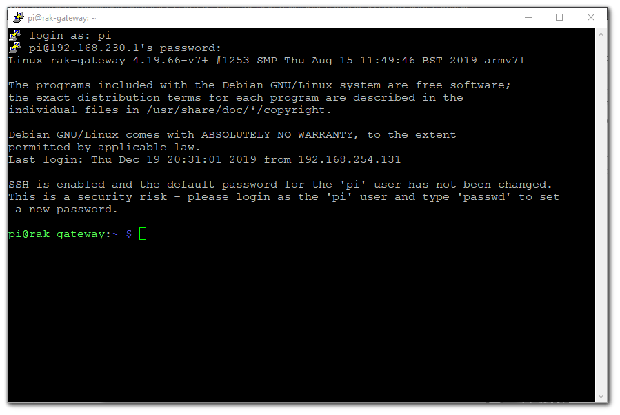 Figure 1: Command line after log in
Mac OS
Open the Terminal of Mac OS. Launch the Terminal application, which is found in /Applications/Utilities/ directory. But you can also launch it from Spotlight by hitting Command + Spacebar, typing Terminal, and then return:
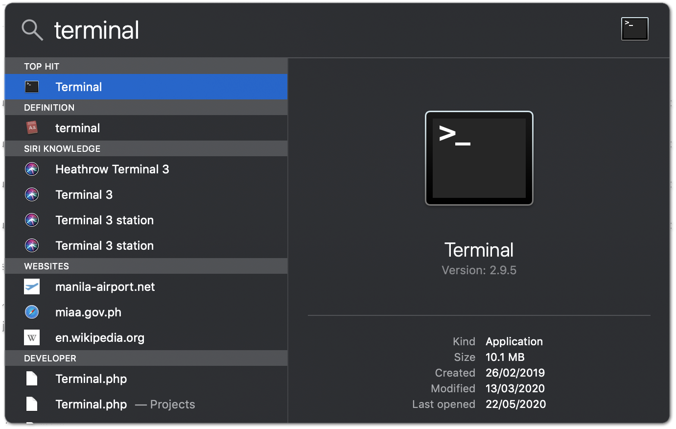 Figure 1: Opening Terminal in Mac OS
Open the terminal of Mac OS. Enter root mode by typing the following command:
sudo -i
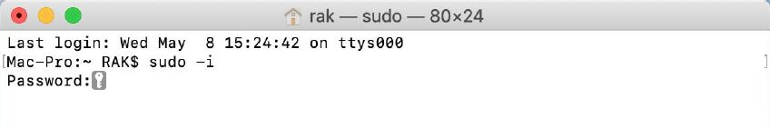 Figure 1: SSH in Mac OS
- If you are not in root mode, enter
ssh pi@192.168.230.1in the terminal to login to your gateway, the default password is raspberry. - If you connect your PC with the gateway through Ethernet Cable, you should enter
ssh pi@192.168.10.10, the default password is raspberry.
Once you have logged successfully into your gateway through SSH, you will see the following image:
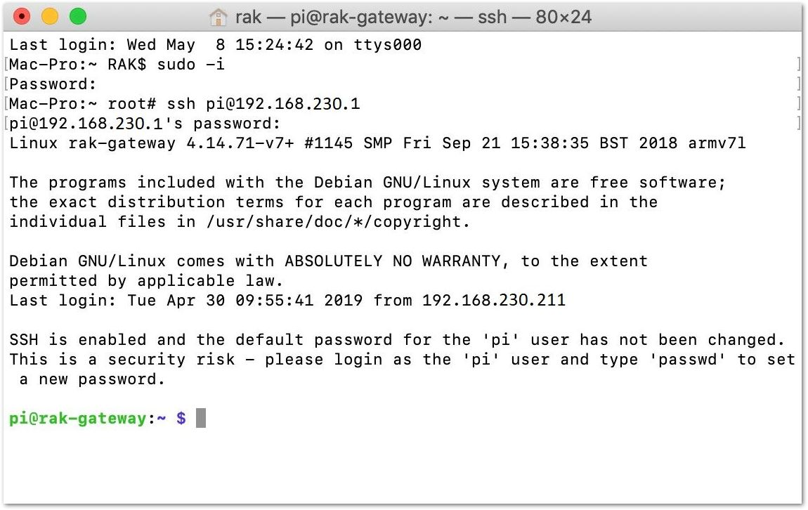 Figure 1: Successful log in notification
Linux OS
If the OS of your PC is Linux, you should do the same as the Mac OS, except for the root mode.
Accessing the Internet
Assuming you have successfully logged into your gateway using SSH. Enter the following command in the command line:
sudo gateway-config
Then, you will see a page the same as Figure 11.
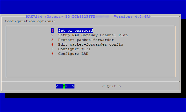 Figure 1: Configuration options for the gateway
- Set pi password - used to set/change the password of the gateway.
- Setup RAK Gateway Channel Plan - used to configure the frequency, on which the gateway will operate, and the LoRaWAN Server which the gateway will work with.
- Restart packet-forwarder - used to restart the LoRa packet forwarder.
- Edit packet-forwarder config - used to open the
global_conf.jsonfile, to edit LoRaWAN parameters manually. - Configure WIFI - used to configure the Wi-Fi settings in order to connect to a network.
- Configure LAN - used to configure the Ethernet adapter settings.
- Configure APN Name (optional) – used to configure the access point name of the mobile network.
- Configure LTE Module (optional) – used to enable/disable LTE automatic dial-up.
Points 7 and 8 can be found only on LTE versions of the gateway.
Connect through Wi-Fi
If you want to connect through Wi-Fi, it can easily be done with the wireless capabilities of the Raspberry Pi 3B+ by choosing 5 Configure WIFI. By default, the RAK7243 Developer works in Wi-Fi AP Mode.
For the gateway to connect to the router, it must work in Wi-Fi Client Mode.
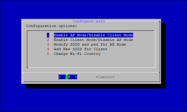 Figure 1: Wi-Fi options configuration
There are 5 options to choose from in the Wi-Fi configuration menu:
There are 5 options to choose from in the Wi-Fi configuration menu:
- Enable AP Mode/Disable Client Mode - the gateway will work in Wi-Fi Access Point Mode after rebooting while the Wi-Fi Client Mode will be disabled (this is the default mode).
- Enable Client Mode/Disable AP Mode - the gateway will work in Wi-Fi Client mode after rebooting, while Wi-Fi AP Mode will be disabled.
- Modify SSID and pwd for AP Mode - used to modify the SSID and password of the Wi-Fi AP. Only works if the Wi-Fi AP Mode is enabled.
- Add New SSID for Client - this is used if you want to connect to a new Wi-Fi Network. Only works in Wi-Fi Client mode.
- Change Wi-Fi Country - this is used to modify the Resident Country to match Wi-Fi standards.
To enable Wi-Fi Client Mode, you have to disable AP Mode first.
Once Wi-Fi AP Mode has been disabled by choosing 2 Enable Client Mode/Disable AP Mode, you can now connect to a new Wi-Fi Network by choosing 4 Add New SSID for Client.
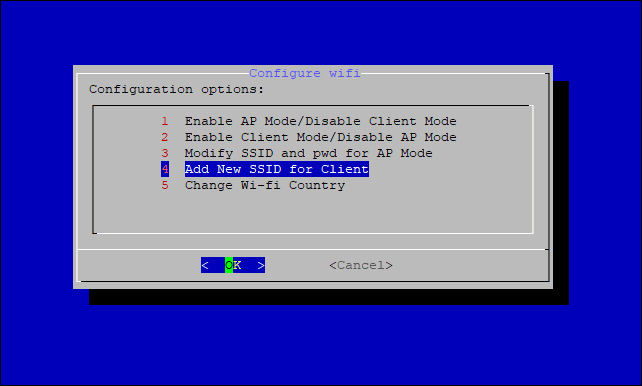 Figure 1: Add a new SSID
- Start by selecting your country of residence.
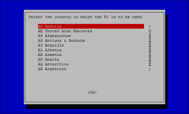 Figure 1: Selecting country of residence
- Enter the SSID of the network you want to connect.
Make sure to input the correct Wi-Fi SSID and password or you will not be able to connect to the RAK7243 again via SSH in Wi-Fi AP Mode. If stuck in this situation, follow this procedure listed in the Reverting to Wi-Fi AP Mode section, which is applicable for all Raspberry Pi based gateways to work again in Wi-Fi AP mode.
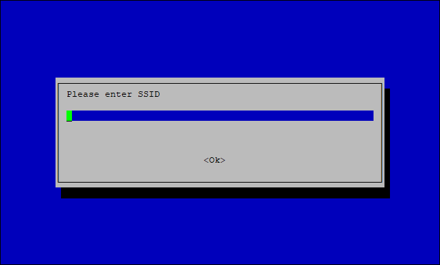 Figure 1: SID of the network you want to connect
- Type the password. If there is none, leave the field empty.
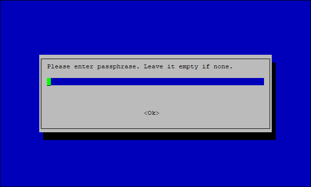 Figure 1: Wi-Fi password
Connect through Ethernet
If you want to connect to the router through an Ethernet cable, do the following steps:
- In the main configuration menu, choose 6 Configure LAN. This will let you set up a static IP address for the gateway’s Ethernet adapter.
- Type a static IP Address according to the IP address of the router you want to connect. The gateway and the router must be in the same network segment, otherwise, the connection will fail.
- By default, the IP Address of the gateway's Ethernet is
192.168.10.10
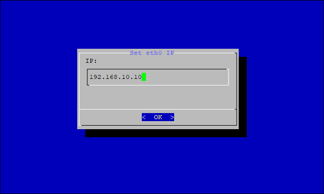 Figure 1: Default gateway Ethernet IP address
- Then configure the IP address of the Router. This is the LAN Interface IP address of the router.
 Figure 1: LAN Interface IP Address of the Router
- Press OK, and the success message will appear.
Reboot
Lastly, reboot the gateway using the command shown below and put it in the command line.
sudo reboot
After reboot, the gateway will connect to the router successfully through Ethernet.
Optional Configurations
The configurations under this section are only optional and situational.
Reverting to Wi-Fi AP Mode
If you have entered either or both incorrect Wi-Fi SSID and password in the Wi-Fi Client Mode setup for the RAK7243C Developer to connect to the router, follow this set of steps for you to work again in Wi-Fi AP Mode and redo the setup.
- Remove the SD card from your RAK7243C WisGate Developer D3+ Gateway and insert it into your PC. Your PC should be able to detect it.
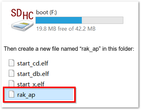 Figure 1: Creating rak_ap file to your SD card
- Using your Command Prompt or Terminal, navigate to your SD card and type this command to generate the
rak_apfile.
cd > rak_ap
- Check if the
rak_apfile is created successfully. If so, re-insert the SD Card into your RAK7243C WisGate Developer D3+ Gateway and it should work again in Wi-Fi AP Mode.
Configuring the Gateway
If you have successfully logged into your gateway using SSH, enter the following command in the command line:
sudo gateway-config
Then you will see a page like in Figure 20.
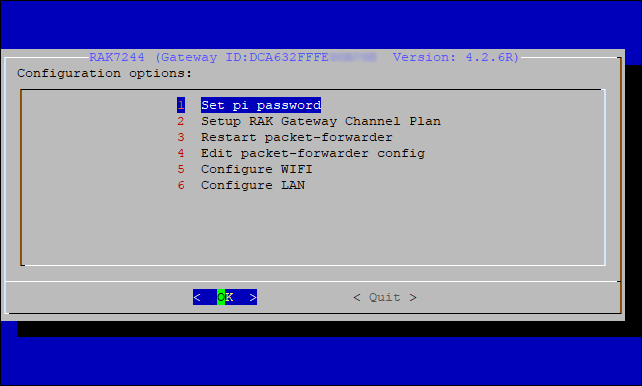 Figure 1: Configuration options for the gateway
- Set pi password - used to set/change the password of the gateway.
- Setup RAK Gateway Channel Plan - used to configure the frequency, on which the gateway will operate, and the LoRaWAN Server which the gateway will work with.
- Restart packet-forwarder - used to restart the LoRa packet forwarder.
- Edit packet-forwarder config- used to open the
global_conf.jsonfile, to edit LoRaWAN parameters manually. - Configure WIFI - used to configure the Wi-Fi settings in order to connect to a network.
- Configure LAN - used to configure the Ethernet adapter settings.
A unique ID will be generated for the gateway. This is also called Gateway EUI and is essential for registering the gateway with any LoRa Network Server (TTN and ChirpStack).
There is also another way to get your Gateway ID. Just enter the command below in the command line:
sudo gateway-version
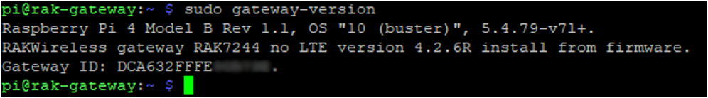 Figure 1: Gateway ID using the command line
Setting a New Password for the Gateway
It is a good security practice to change the default password raspberry, which is the same on all Raspberry Pi devices.
- First, choose 1 Set pi password option.
 Figure 1: Set Pi Password
2. Next, press "Yes" and you will be asked to enter your new password twice then press "Enter".
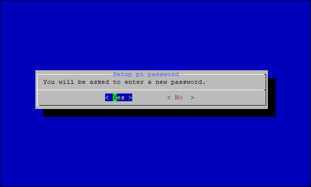 Figure 1: Confirm Password Change
- А success message for changing the password will then pop up.
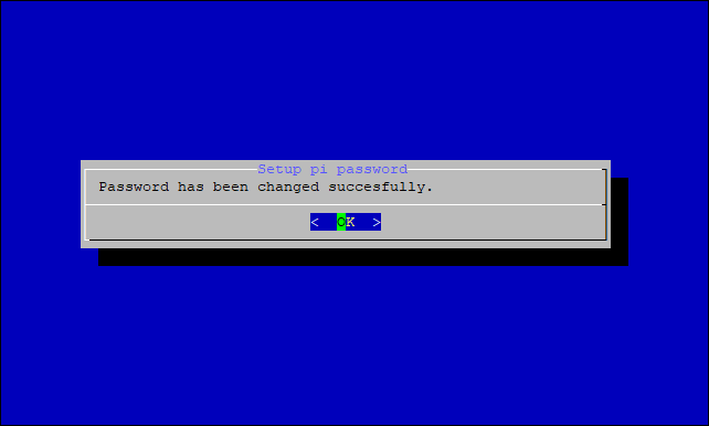 Figure 1: Successful password change
Setup RAK Gateway Channel Plan
This menu allows you to select your LoRa frequency band and one of the two available Networks Server options by choosing 2 Setup RAK Gateway Channel Plan.
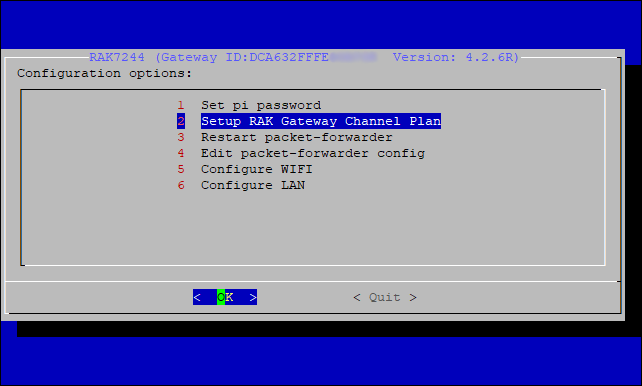 Figure 1: Choosing a channel plan
You can choose one of two supported LoRa servers here: TTN or ChirpStack.
Server is TTN
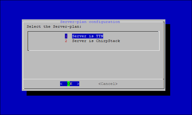 Figure 1: TTN server
- TTN (The Things Network) - If you choose TTN as the LoRa Server, you will see a page the same as shown in Figure 27. Visit LoRa Alliance Regional Parameters for more information on your local frequency plan. This will allow you to choose the correct plan.
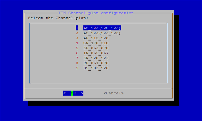 Figure 1: Selecting the TTN channel plan
After choosing the correct frequency, a success message will appear, as shown in Figure 28.
 Figure 1: Successfully changed the frequency
When a channel plan is selected, the gateway is configured to connect to the nearest cluster to the region. If new clusters are presented, the channel plans will be updated. For now, the only available clusters are as follows:
- Europe: eu1.cloud.thethings.network
- Australia: au1.cloud.thethings.network
- North America: nam1.cloud.thethings.network
Server is Chirpstack
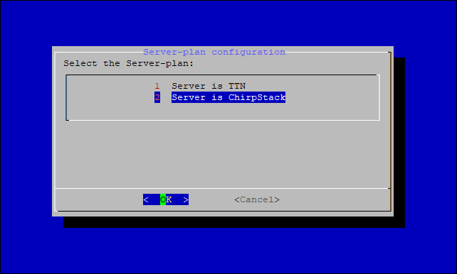 Figure 1: Chirpstack server
ChirpStack - If you choose Chirpstack as your LoRa Server, you will see the following page with two options available:
- ChirpStack Channel Plan Configuration - used to configure your Regional Frequency Band.
- ChirpStack ADR Configure - used to enable/disable the Adaptive Data Rate (ADR) functionality.
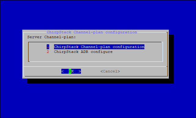 Figure 1: Configure ChirpStack channel plan
First, select 1 ChirpStack Channel-plan configuration for configuring your frequency channel.
Figure 1: Regional frequency band optionThen set the IP address of the ChirpStack.
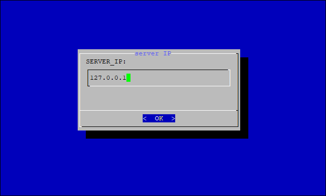 Figure 1: Default LoRaServer IP address
The default IP Address is 127.0.0.1. If you want to use an external LoRaServer, you need to set it to its IP address.
- If you have instead selected Chirpstack ADR Configure, you can enable/disable the Adaptive Data Rate (ADR) functionality:
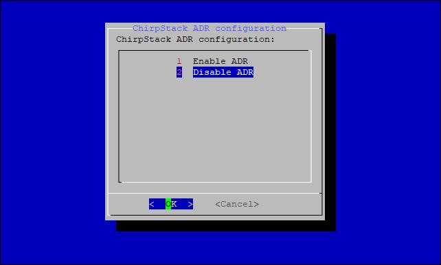 Figure 1: Chirpstack ADR Enable/Disable
If you want to use ChirpStack for LoRa Network server, refer to the LoRaWAN Network Server Guide documentation under Connecting with ChirpStack section.
Connect through an LTE Network
The RAK7243C comes with the RAK2013 Cellular, making it capable of connecting through LTE network. In this section, you will learn how to connect your gateway to an LTE network.
-
Insert a SIM card of the appropriate type and size into the SIM card slot. Power on the gateway.
-
Log into the gateway through SSH, and enter the following command:
sudo gateway-config -
In the main configuration menu, choose 7 Configure LTE Module.
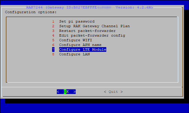 Figure 1: Configure LTE module
Two configuration options are available for your LTE.
- Enable LTE Automatic Dial-up - the default option and is used to enable automatic connection during start-up.
- Disable LTE Automatic Dial-up - used to disable automatic connection during start-up.
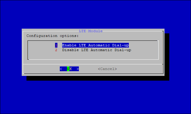 Figure 1: LTE configuration options
-
Next, you need to configure the LTE network operator’s information. Make sure to disable the automatic connection on the start-up feature before starting.
-
Execute the command below in the console to start the minicom tool:
sudo minicom -D /dev/ttyAMA0 -b 115200
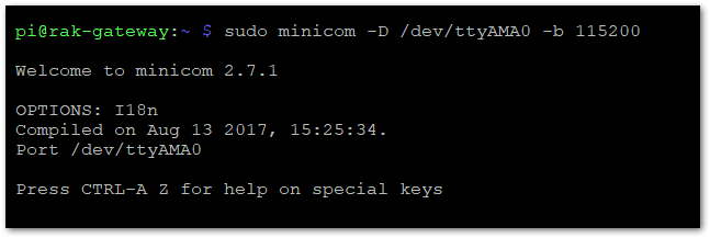 Figure 1: Minicom tool
- Next, try entering the AT command in the tool, if the return message is OK, it means you have opened the serial port successfully.
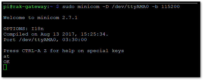 Figure 1: AT Command in Minicom
If you cannot see the at, which you just entered. Try to hold CTRL+A, then press Z, then E. This should allow you to go to the command entering mode.
- Next, execute the AT command
at+cops=?to look for all available LTE networks in range.
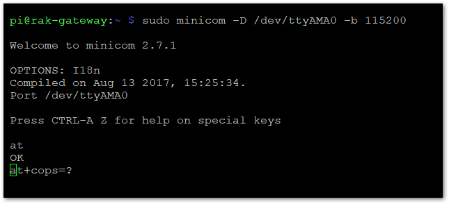 Figure 1: AT Command for LTE network query
This may take a couple of seconds. After that, you'll see the available LTE network information similar to Figure 39.
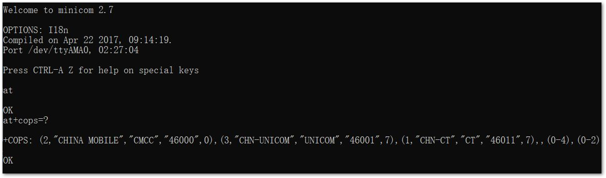 Figure 1: LTE network example
Figure 39 shows the available LTE network in China. This information may vary depending on the available network in your region. For instance, in China, the available networks are CHINA MOBILE, CHN-UNICOM, or CHN-CT.
- Next, execute the AT command below to set the information of the LTE network operator that you want to use.
- XXX - this parameter is set to describe the network operator. For example,
CHINA MOBILE,CHN-UNICOM, orCHN-CT. - YYY - this parameter is set as the last value of every operator. Choose the network with 0 value as this is the currently used network.
Now, take this LTE network in Europe (Bulgaria) as an example:
 Figure 1: Sample LTE Networks in EU
Then, using the sample AT command described above, the command will be:
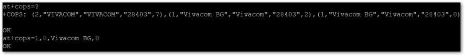 Figure 1: Sample AT Command for LTE network
Lastly, you will receive OK, which means you have successfully configured the LTE network.
To exit Minicom, press Enter, Ctrl + A then press Q. A pop-up will appear and choose Yes.
- Proceed to set the APN name for the pppd process. From the main configuration menu, choose 6 Configure APN name.
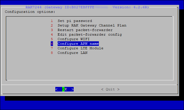 Figure 1: Configure APN name
- Then, you will see the window option below where you can change the APN Name or retain its default name.
If you want to modify the APN Name, make sure it is a real and valid APN Name.
 Figure 1: APN name
- Lastly, set the baud rate. The default value is
115200.
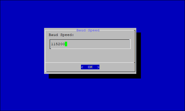 Figure 1: Baud rate setting
You have now finished configuring your LTE network. Now, you can test and verify the connection as follows:
Execute the following command in the terminal:
sudo pppd call gprs
There will be a series of logs. After that, you will see the following information at the end of the log.
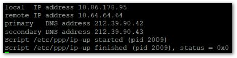 Figure 1: IP address Information
You will be assigned an IP address (local and remote) along with the DNS addresses. Having this information signifies that your connection has been successfully established.
Also, do not forget to re-enable the automatic LTE connection on start up
 Figure 1: Enabling the automatic LTE connection during start-Up