RAK7267 WisGate Soho Pro Unboxing & Installation
For outdoor gateways, RAKwireless recommends completing basic gateway configuration indoors before field installation. This helps verify gateway access, Internet connectivity, SIM card status, and LoRaWAN® server settings before the gateway is permanently installed outdoors.
This guide is organized by setup scenario. You can first choose the scenario that matches your deployment stage, then follow the referenced hardware setup procedures.
Prerequisites
Package Inclusions
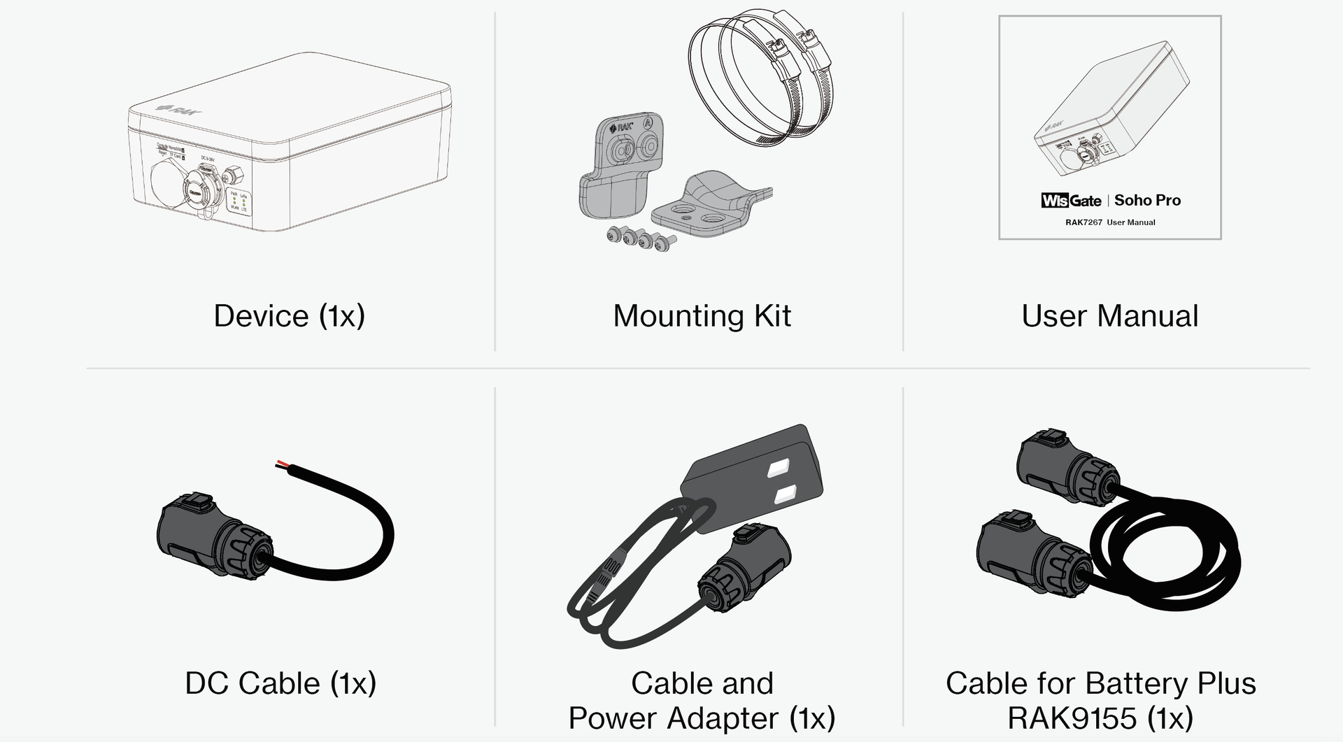 Figure 1: RAK7267 package list
The packing list shows cables for all power options supported by the gateway. This may not exactly match the cable options out of the box, depending on the bundle you purchased.
Additional Hardware Required
- A Windows/MacOS/Linux Computer – For configuration via Web UI
- NanoSIM Card – Size:12 x 9 x 0.67 mm
Installation Workflow
This section describes the recommended installation workflow for outdoor gateway deployments.
Indoor Pre-Configuration
Use this scenario when you want to power on and configure the gateway indoors before installing it outdoors.
During indoor pre-configuration, you can complete the basic hardware setup required for software configuration.
Complete the following sections:
- Insert SIM Card
- Power On the Gateway
- Continue with the Quick Start Guide to:
- Access the WisGateOS 2 Web UI
- Configure Internet access
- Configure the LoRaWAN® Network Server connection
After the indoor pre-configuration is complete, power off the gateway and continue with outdoor field installation.
Outdoor Field Installation
Use this scenario when the gateway is ready to be permanently installed outdoors.
Outdoor field installation includes mounting the gateway, applying gateway grounding, connecting the final power source, and verifying gateway status after installation.
Complete the following sections:
-
NOTE
If the SIM card has already been inserted during indoor pre-configuration, you can skip this step.
-
Verify gateway status in WisGateOS 2 or WisDM after installation.
Hardware Setup Procedures
Insert SIM Card
- If the gateway is running WisGateOS 2.3.1 or later, the SIM card slot supports hot-swapping.
- For versions earlier than WisGateOS 2.3.1, the SIM card slot is not hot-swappable. Always power off the gateway before inserting or removing the SIM card.
- Start by unscrewing the cap of the NanoSIM interface on the gateway Unify Enclosure to expose the SIM card slot.
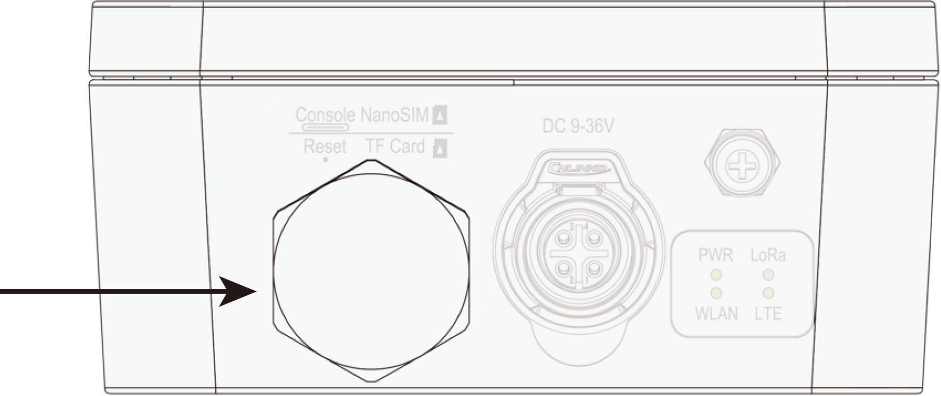 Figure 1: SIM card slot
- Push the SIM card into the card slot according to the placement method marked on the interface.
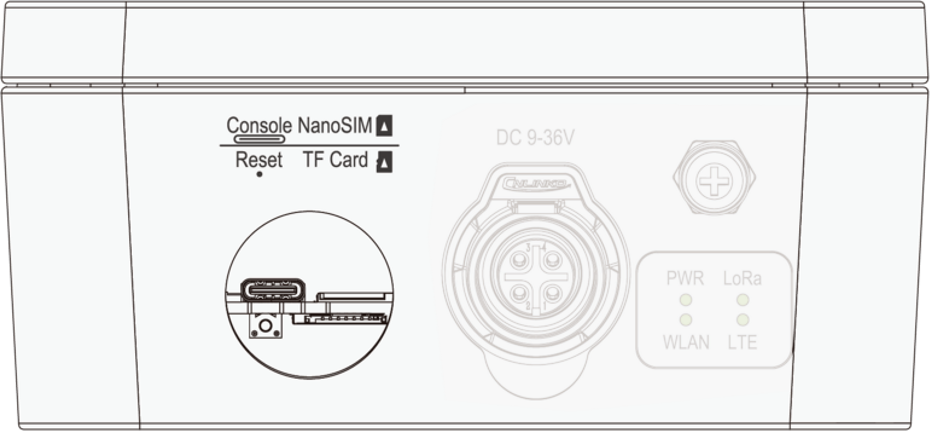 Figure 1: Inserting the SIM card
- Once completed, screw back the metal cap. Make sure it is tightly screwed.
Mount the Gateway
- Attach the pole mounts to the Unify Enclosure using four (4) M3 × 8 mm screws with washers. Refer to Figure 5 for the correct mounting positions.
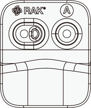 Figure 1: Pole mounts marked with the letter A
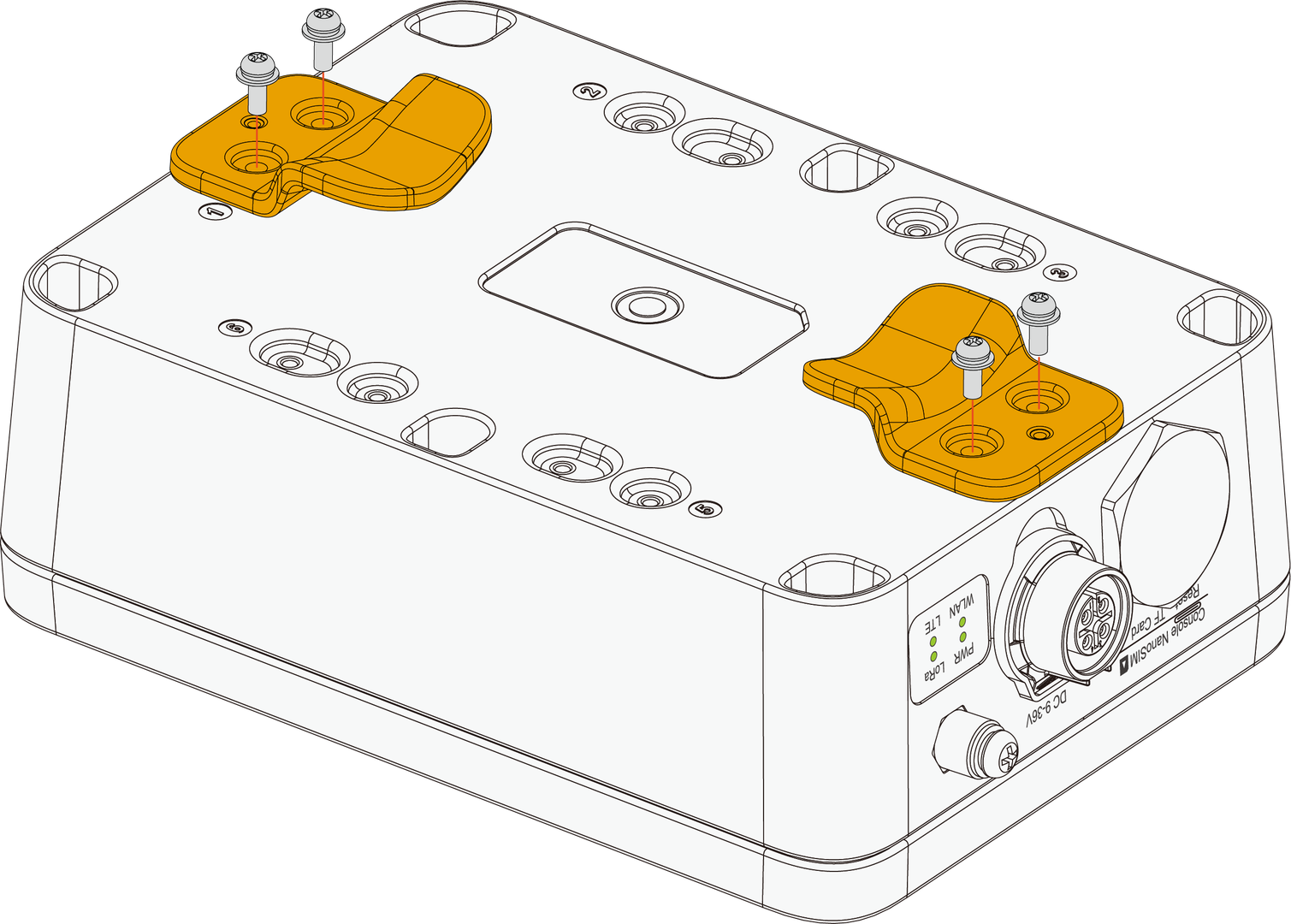 Figure 1: Fixing the pole mounts on the enclosure
- After fixing the mounts to the enclosure, use two (2) steel strips (65–89 mm) to secure the Unify Enclosure onto the pole.
The steel strips ONLY support 65~89 mm diameter pole.
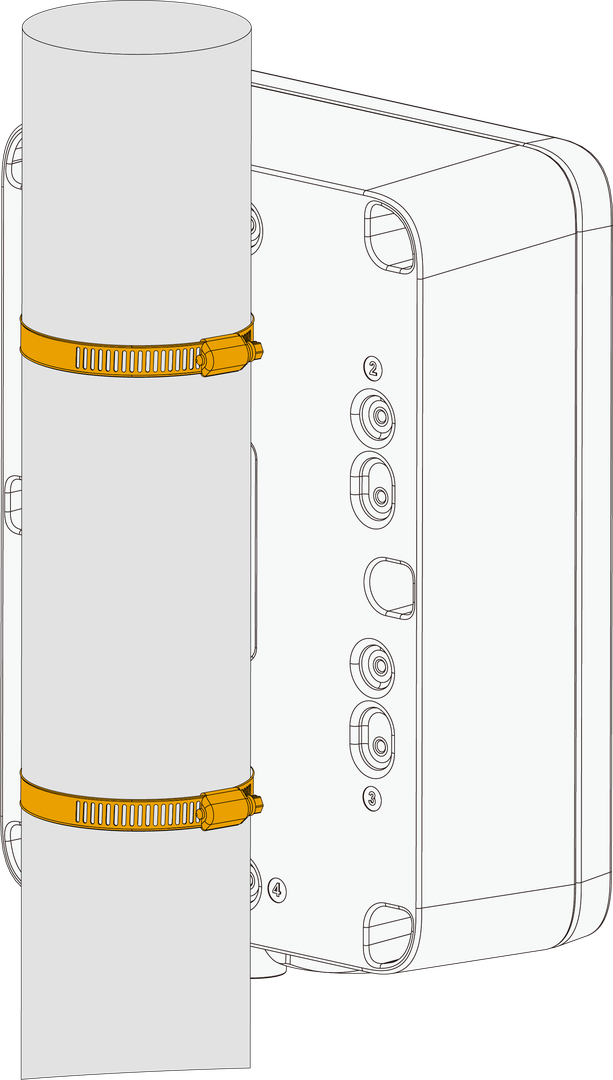 Figure 1: Fixing the enclosure on the pole
Gateway Grounding
Lightning strikes can generate powerful electrical surges that may harm sensitive electronic devices. It is essential to take appropriate precautions to minimize the risk of damage. The warranty provided does not cover damages resulting from lightning strikes or other acts of nature.
Gateway grounding connects the gateway enclosure to a reliable grounding point. This helps discharge electrical surges safely and reduces the risk of damage to the gateway and connected equipment.
To ground the gateway:
- Locate the grounding screw on the bottom side of the gateway casing.
- Use 10 AWG or thicker grounding wire. Connect one end of the grounding wire to the gateway grounding screw.
- Connect the other end to a proper grounding point, such as:
- A grounding rail mounted on the building wall
- A grounding bar in field deployments
- Another qualified protective earth grounding system
Power On the Gateway
The gateway supports various power supply options. Connect it to the proper source using the power cables included in your package.
Power Adapter
When the gateway is deployed indoors, it is recommended to use the provided cable and power adapter to power the gateway.
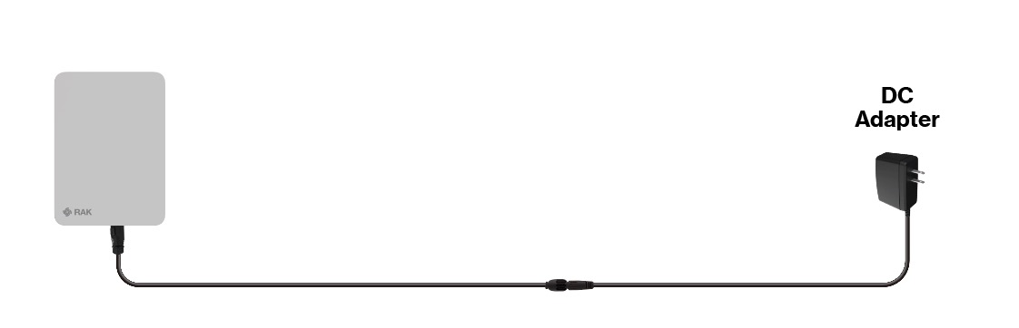 Figure 1: Powering the gateway through a DC adapter
DC Power Input (9–36 VDC)
If you use a customized external DC power supply, connect it to the gateway using the DC cable. The supported input voltage range is 9–36 VDC.
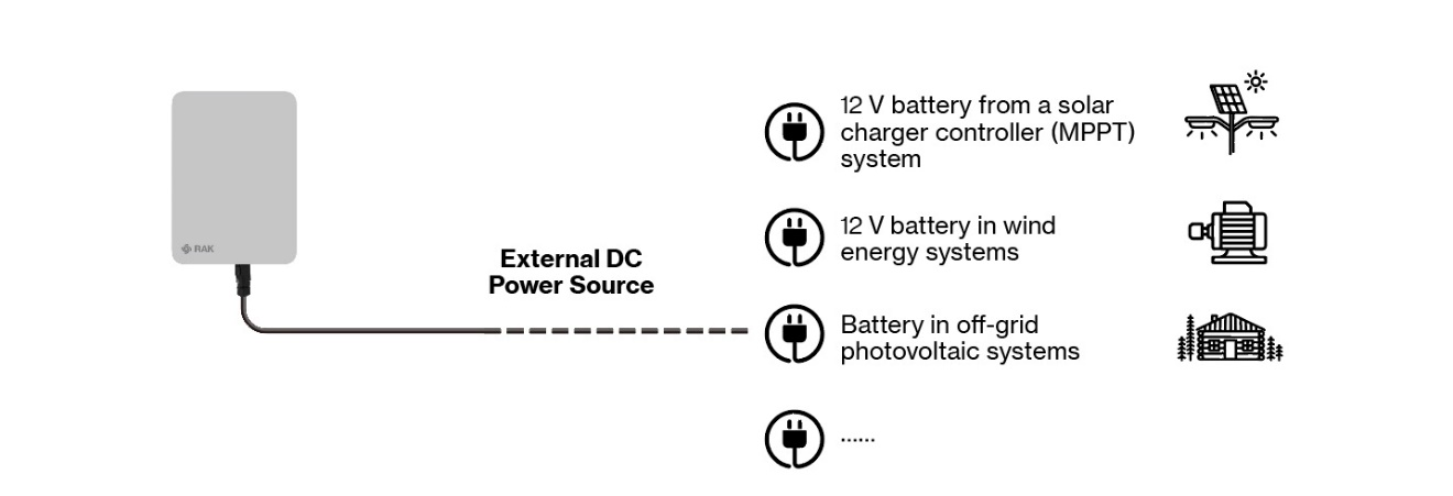 Figure 1: Powering the gateway through an external DC power source
RAK9155 Battery Plus
For outdoor deployment scenarios, it is recommended to use the RAK9155 Battery Plus as the power supply. Use the dedicated cable included for connecting to the Battery Plus.
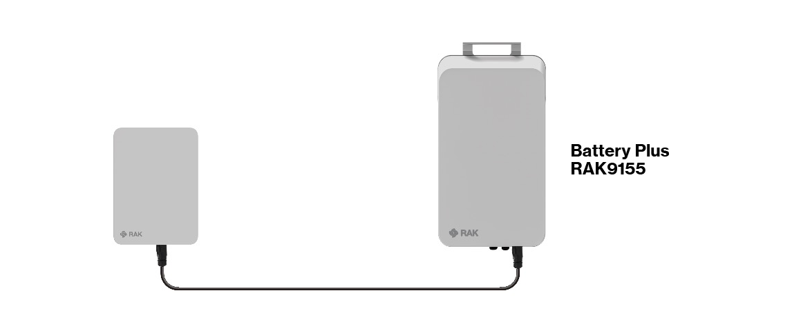 Figure 1: Powering the gateway through RAK Battery Plus
RAK9155 Battery Plus is not included in the bundle, it needs to be purchased separately.