RAK7289V2/RAK7289CV2 Unboxing & Installation
For outdoor gateways, RAKwireless recommends completing basic gateway configuration indoors before field installation. This helps verify gateway access, Internet connectivity, SIM card status, and LoRaWAN® server settings before the gateway is permanently installed outdoors.
This guide is organized by setup scenario. You can first choose the scenario that matches your deployment stage, then follow the referenced hardware setup procedures.
Prerequisites
Package Inclusions
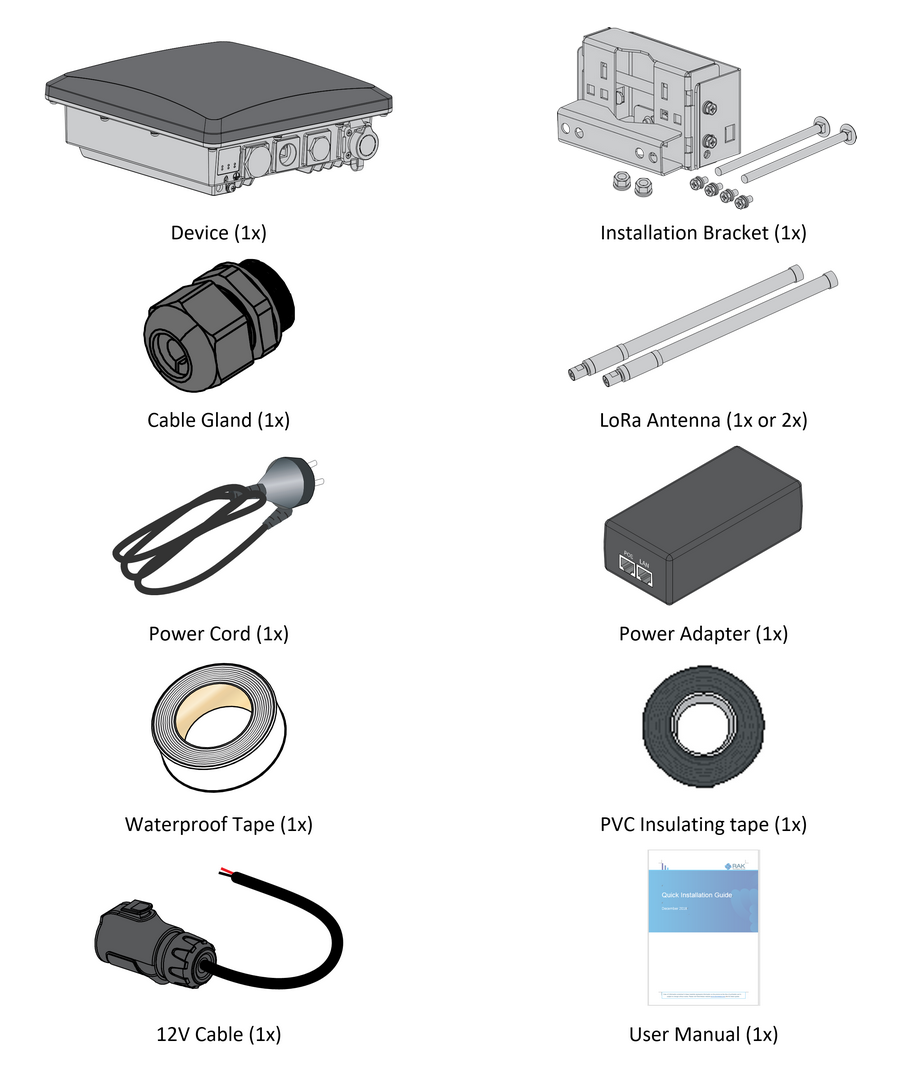 Figure 1: RAK7289V2/RAK7289CV2 package list
LoRa® antenna is not included and must be purchased separately.
Additional Hardware Required
-
Ethernet Cable (RJ-45 Port) – Required for network setup
-
A Windows/MacOS/Linux Computer – For configuration via Web UI
-
LoRa® Antenna(s) – One or two antennas may be required, depending on your gateway model
-
NanoSIM Card (for LTE version) – Size: 12 x 9 x 0.67 mm
Installation Workflow
This section describes the recommended installation workflow for outdoor gateway deployments.
Indoor Pre-Configuration
Use this scenario when you want to power on and configure the gateway indoors before installing it outdoors.
During indoor pre-configuration, you can complete the basic hardware setup required for software configuration.
Complete the following sections:
- Insert SIM Card — for cellular models only
- Attach Antennas and Cables
- Power On the Gateway
- Continue with the Quick Start Guide to:
- Access the WisGateOS 2 Web UI
- Configure Internet access through Ethernet, Wi-Fi, or Cellular
- Configure the LoRaWAN® Network Server connection
After the indoor pre-configuration is complete, power off the gateway and continue with outdoor field installation.
Outdoor Field Installation
Use this scenario when the gateway is ready to be permanently installed outdoors.
Outdoor field installation includes mounting the gateway, installing antennas and cables, applying grounding and lightning protection, weatherproofing the connectors, and connecting the final power source.
Complete the following sections:
-
Insert SIM Card — for cellular models only
NOTEIf the SIM card has already been inserted during indoor pre-configuration, you can skip this step for cellular models.
-
Verify gateway status in WisGateOS 2 or WisDM after installation
Hardware Setup Procedures
Insert SIM Card (For cellular models)
- If the gateway is running WisGateOS 2.3.1 or later, the SIM card slot supports hot-swapping.
- For versions earlier than WisGateOS 2.3.1, the SIM card slot is not hot-swappable. Always power off the gateway before inserting or removing the SIM card.
- Start by unscrewing the cap of the NanoSIM interface on the gateway enclosure to expose the SIM card slot.
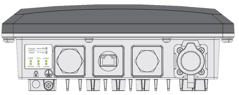 Figure 1: Unscrewing the cap of the NanoSIM interface
- Push the SIM card into the card slot according to the placement method marked on the interface.
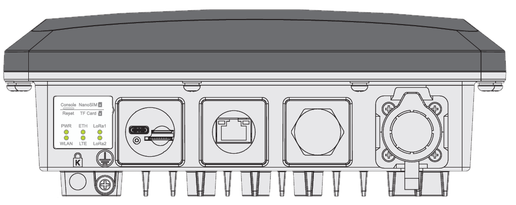 Figure 1: Inserting the SIM card
- Once completed, screw back the metal cap. Make sure it is tightly screwed.
Mount the Gateway
- Fix the bracket included in the mounting kit on the bottom of the enclosure with four M6*12 screws.
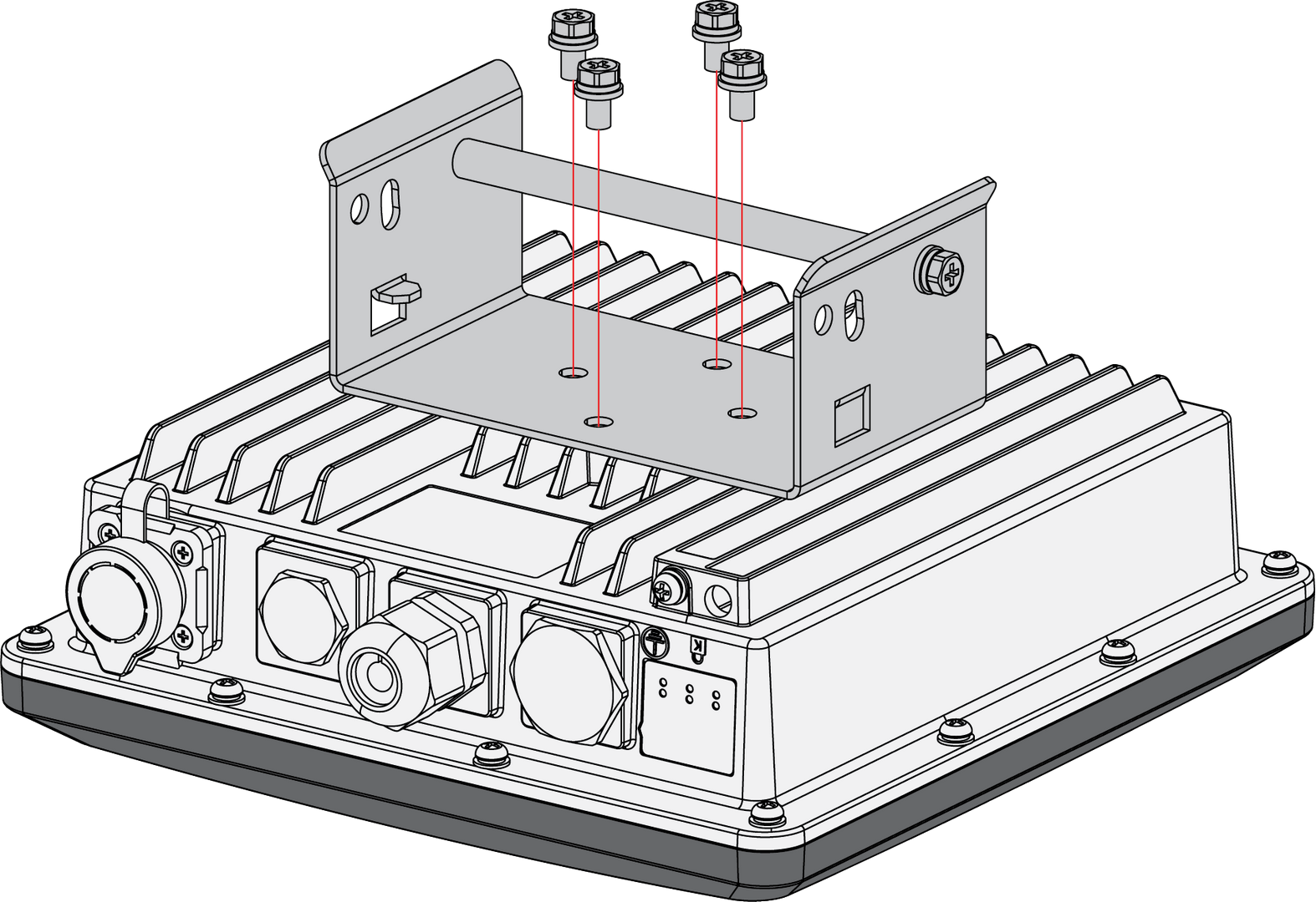 Figure 1: Mounting the bracket to the enclosure
- Position the pole clamps together around the pole, then tighten them with bolts, washers, and nuts.
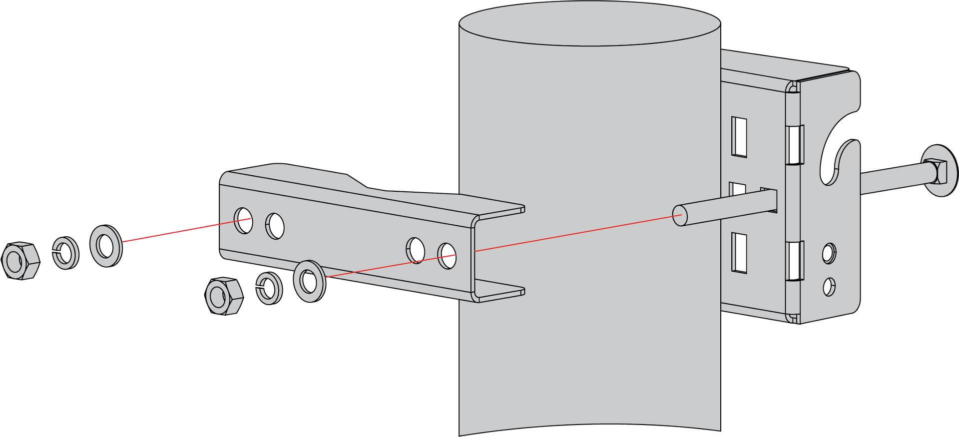 Figure 1: Mounting the clamps to a pole
The diameter of the pole that is supported by the brackets is 50-100 mm. If the pole diameter is more than this value, hose clamps can be used. The standard mounting kit does not include hose clamps. If needed, they should be purchased separately.
The clamp's back also has openings for hose clamps that are not included in the mounting kit.
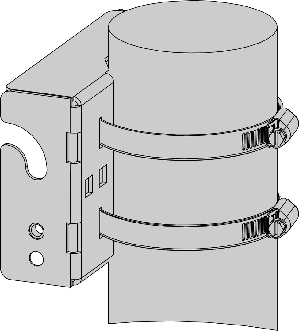 Figure 1: Mounting using hose clamps
-
Mount the enclosure and secure it to the bracket.
 Figure 1: Fastening the enclosure to the bracket
- Hang the enclosure on the pre-installed mounting hook (①).
- Use the adjustment screw (②) to fine-tune the vertical angle of the gateway. This allows you to correct any tilt caused by the enclosure‘s draft angle or pole misalignment, ensuring that the antenna is perfectly vertical.
- Once the alignment is complete, secure the enclosure by tightening the two M6×12 screws (③).
Gateway Grounding and Lightning Protection
Lightning strikes can generate powerful electrical surges that may harm sensitive electronic devices. It is essential to take appropriate precautions to minimize the risk of damage. The warranty provided does not cover damages resulting from lightning strikes or other acts of nature.
For outdoor deployments, protection should cover the gateway enclosure, outdoor antenna connections, and the Ethernet/PoE connection to indoor network devices. The protection system typically includes:
- Gateway grounding: Provides a safe discharge path for electrical surges through the gateway enclosure.
- Antenna lightning protection: Protects LoRa® antenna connectors from lightning-induced surges.
- Ethernet/PoE surge protection: Protects indoor network devices, such as PoE injectors, switches, or routers, from surges carried through the Ethernet cable.
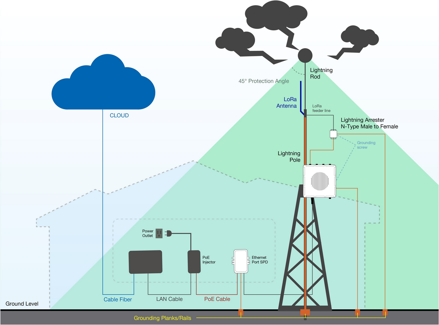 Figure 1: Gateway grounding and lightning protection setup
Gateway Grounding
Gateway grounding connects the gateway enclosure to a reliable grounding point. This helps discharge electrical surges safely and reduces the risk of damage to the gateway and connected equipment.
To ground the gateway:
- Locate the grounding screw on the bottom-left side of the gateway.
- Use 10 AWG or thicker grounding wire. Connect one end of the grounding wire to the gateway grounding screw.
- Connect the other end to a proper grounding point, such as:
- A grounding rail mounted on the building wall
- A grounding bar in field deployments
- Another qualified protective earth grounding system
Antenna Lightning Protection
LoRa® antenna lightning protection helps protect the gateway antenna ports from surge currents induced by lightning or nearby electrical discharge.
For each LoRa® antenna connection:
- Install a lightning arrestor on each antenna’s N-type terminal (LoRa®). The arrestors must be N-type Female to Male to match the antenna and gateway interface.
- Use 10 AWG or thicker grounding wire to connect the arrestor grounding terminal to the grounding rail mounted on the building wall or a grounding bar in field deployments.
- Keep the grounding wire as short and straight as possible to reduce surge impedance.
Ethernet/PoE Surge Protection
Ethernet/PoE surge protection helps protect indoor network devices connected to the outdoor gateway, such as PoE injectors, switches, and routers.
To protect indoor equipment and circuitry connected to the gateway, it is recommended to install an Ethernet SPD (Surge Protection Device) on the Ethernet cable path between the outdoor gateway and the indoor network equipment.
For Ethernet/PoE protection:
- Install the Ethernet SPD between the gateway and the indoor PoE injector, switch, or router.
- Connect the SPD grounding terminal to a proper building grounding point.
- Make sure the Ethernet cable and SPD are suitable for the required network speed and outdoor deployment conditions.
No additional Ethernet surge protection is required on the gateway side. The gateway already has a built-in surge protection system for the Ethernet connection.
Recommended Equipment
-
Lightning Arrestor for the LoRa Antennas: This surge protective device safeguards transceivers against over-voltage and surge current induced by lightning strikes.
-
Pulsar cable RAK9731: The RAK9731 Pulsar cable is utilized for lightning protection with the RAK7289V2/RAK7289CV2. This cable features an N-Type Male to N-Type Female configuration and is available in custom lengths of 1.5 m, 3 m, 5 m, 10 m, or longer. It is constructed with LMR-400 coaxial cable and N-type connectors.
-
Signal Surge Protective Device: This device is designed to protect Category 6 or Class E cables, safeguarding equipment from surge and over-voltage events caused by lightning or internal system factors. It finds extensive application in office and industrial network wiring projects, as well as telecommunications setups including Gigabit Ethernet, ATM, ISDN, and VoIP systems.
-
Ethernet Cabling: For outdoor surge protection systems, a CAT5 Ethernet Cable is recommended. It serves to establish connections between the PoE injector, Ethernet SPD, router/switch, and the Ethernet/PoE port.
Attach Antennas and Cables
After completing lightning protection installation, connect the required antennas and cables according to your deployment setup.
Attach LoRa® Antennas
Connect the LoRa® antenna(s) to their respective antenna port(s). If lightning arrestors have been installed, connect the antennas through the lightning arrestors.
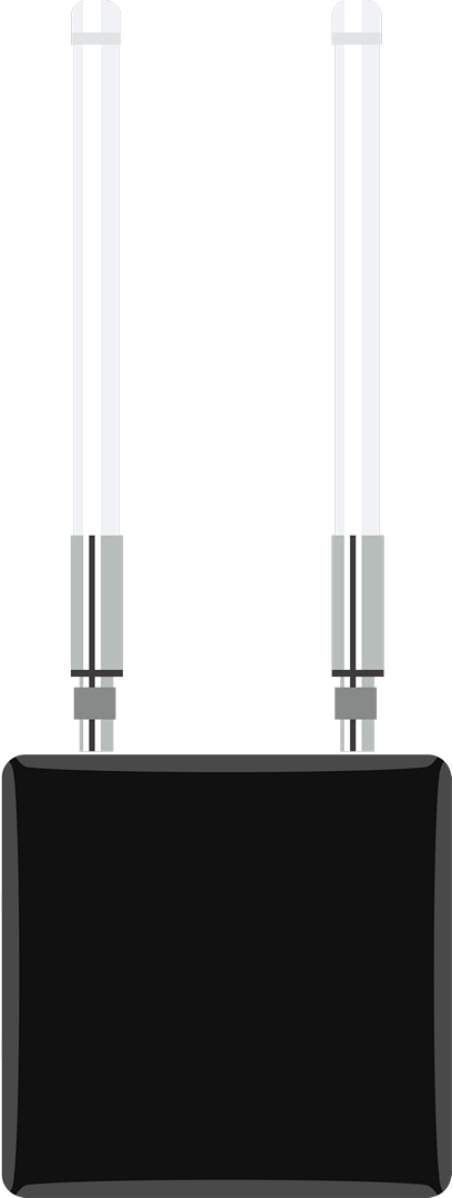 Figure 1: RAK7289V2/RAK7289CV2 with attached antennas
Connect Ethernet/PoE Cable
Connect the Ethernet cable based on your power and network setup. If an Ethernet SPD has been installed, route the Ethernet cable through the SPD according to the surge protection setup.
- If using PoE for power, connect the Ethernet cable to the ETH (PoE) port on the gateway.
- If using Ethernet for wired network access, connect the Ethernet cable to the ETH (PoE) port and the other end to the PoE injector, switch, or router as required.
Weather Protection
To better protect the Ethernet cable gland and all antenna connectors from from moisture and environmental damage, you need to cover them with PVC tape.
- Clean the surface area of the connector that will be wrapped. Wrap a layer of PVC tape with a 50% overlap according to the rotation direction of the connector. Continue wrapping the PVC tape to about 10 mm below the end of the connector.
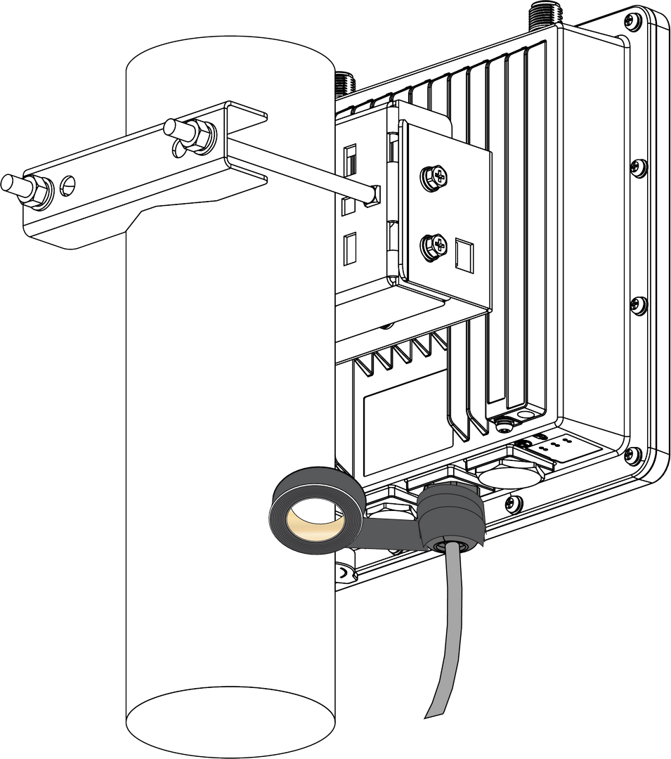 Figure 1: Wrapping with PVC tape
- Cut off about 50 cm waterproof tape. Stretch it to double the length. Wrap three layers around the connector with a 50% overlap. Hold the tape in place with your hand for a few seconds.
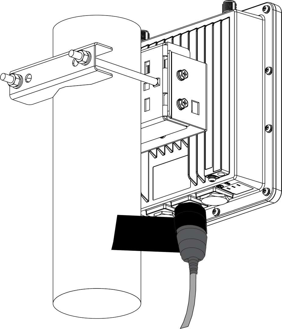 Figure 1: Wrapping with waterproof tape
- Wrap three additional layers with PVC tape with natural uncoiling force and a 50% overlap. Ensure to cover the head and the tail of the connector.
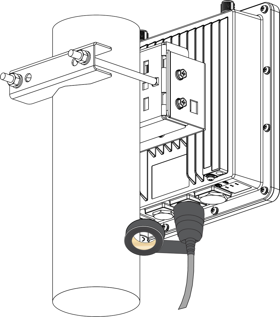 Figure 1: Final PVC wrapping
Power On the Gateway
Do not power the device if any antenna port has been left open.
The gateway supports multiple power supply options. Connect the gateway to the appropriate power source based on your needs.
PoE (Power over Ethernet)
- Connect the Ethernet cable—already attached to the gateway’s ETH (PoE) port—to the PoE port of the injector.
- Plug the injector into a power outlet to power up the gateway.
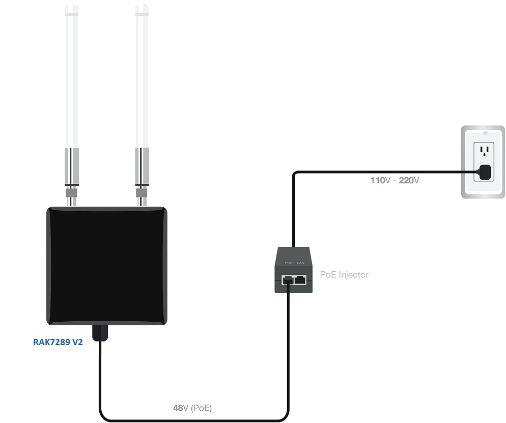 Figure 1: Powering the gateway using PoE
DC Power Input (12 V DC)
The gateway supports an external 12 V DC power supply through its DC input port. You can either use the included power cable to connect the gateway to your own 12 V DC power source, or power the gateway with the RAK9155 Battery Plus.
RAK9155 Battery Plus is not included in the bundle, it needs to be purchased separately.
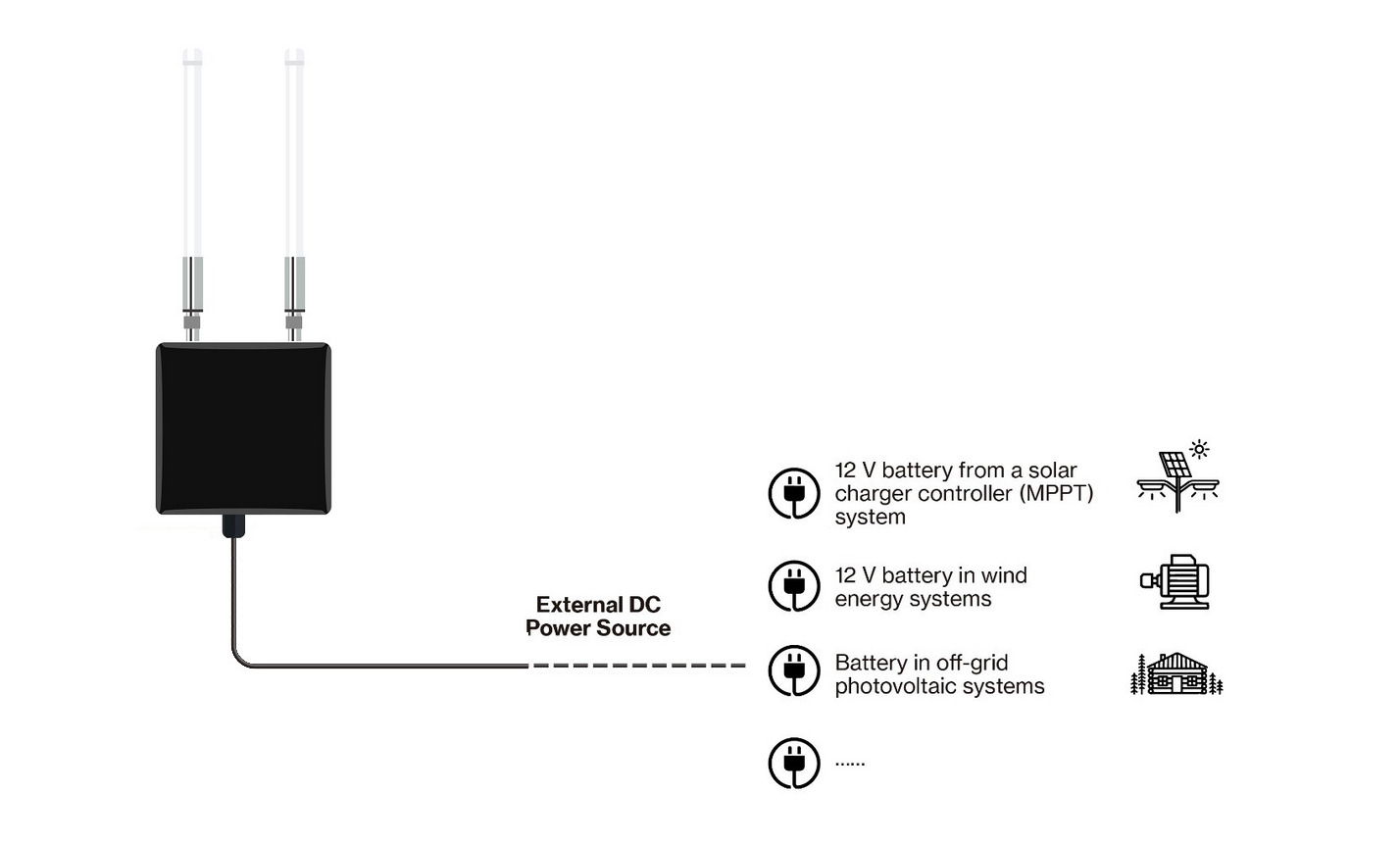 Figure 1: Powering the gateway using external DC power supply