RAK8213 WisLink Cellular mPCIe Installation Guide
Prerequisites
The following two sections will provide a list of the components and tools you need to get started with the development board. Some of those are included in the package, others you need to provide yourself.
Hardware Tools
- RAK8213 WisLink Cellular mPCIe
- Raspberry Pi 3/4
- RAK8213 Pi HAT
- LTE and GPS antennas (included)
- Hologram SIM card
Software Tools
- Balena Etcher (a tool for burning the firmware on the SD card)
- Latest RAK8213 Firmware
Device Firmware Setup
An easy and quick way to have a fully functional gateway is by using a Precompiled Firmware Image. This section provides step-by-step instructions on how to install the image on the SD card used for the gateway.
Burn the Latest Firmware
- Download the latest firmware, which is based on the Raspbian OS.
- Use an image writing tool to install the firmware on the SD card. For this, you will be using Etcher, which is an open-source utility used for burning image files.
- Insert your SD card into the SD card reader and plug it into your computer.
- Open the Etcher software and select the downloaded image file.
Your SD card should be automatically detected by the Etcher software. If not, secure a proper connection.
Click Flash and wait for a couple of minutes until it displays Flash Complete.
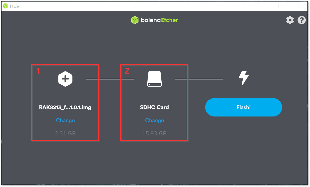 Figure 1: Balena Etcher Software
Assemble the RAK8213
For the RAK8213 module to function as an extension for the Raspberry Pi, you need to assemble several components.
Insert the SIM Card
Insert the SIM card in the slot that sits on the back of the RAK8213. Best do this now as later on, it will be more difficult to access.
Mount the RAK8213 Module
Insert your RAK8213 module into the mPCIe slot on the RAK8213 Pi HAT. Make sure the card fits snugly into the connector. It should end up sticking out at an angle of 45°.
Gently press it down and fasten it with two (2) screws. If you have positioned the card correctly, the screw holes on the RAK8213 will match the ones on the RAK8213 HAT.
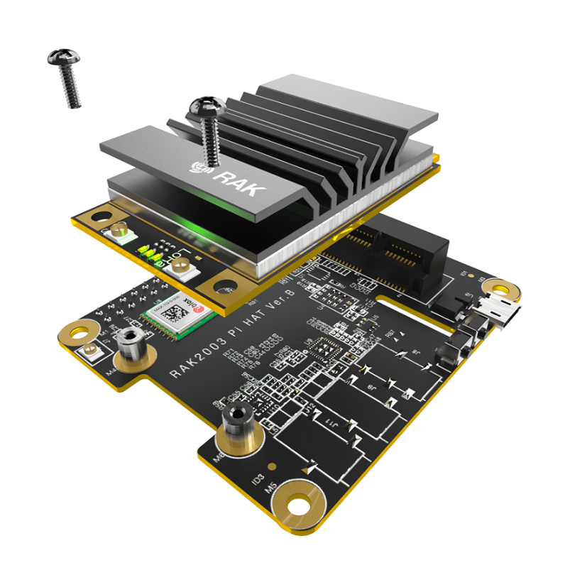 Figure 1: Assembly of the RAK8213 Module and the HAT
Connect the Antennas
The module comes with two (2) antennas: Cellular and GPS. Both have pigtail cables with uFL connectors that fit onto the corresponding ports on the RAK8213.
The GPS antenna is on the right when looking at the module from the side where the BG96 is. Match each antenna to its corresponding port and gently press until the connectors fit together.
It is not recommended to power the device with the antennas detached. This might damage the circuitry.
Mount the HAT
Take the RAK8213 HAT, which now has the RAK8213 securely mounted on top, and place it over the Raspberry Pi. Both the Pi and the HAT have a 40-pin connector that should fit together snugly when pressed on top of each other.
Power the RAK8213
The RAK8213 requires additional power via the Micro USB port on the RAK8213 Pi HAT.
Attach a standard Micro USB to USB cable, connecting one of the Raspberry Pi's USB ports to the Micro USB port on the RAK8213 HAT.
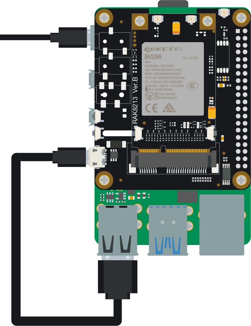 Figure 1: Power Connection for the RAK8213 HAT
Insert the SD Card
Insert the SD card with the firmware you flashed in the previous step into the SD card slot on the bottom of the Raspberry Pi.
Boot
Power the Raspberry Pi via the Micro USB port (Pi3) / USB Type-C port (Pi4). As this is the first time booting the OS, wait for a couple of minutes for everything to set up.
It is recommended to use at least a 2 A power supply.


