RAK2560 WisNode Sensor Hub Quick Start Guide
Prerequisites
Before you begin, prepare the following items:
Hardware
- RAK2560 WisNode Sensor Hub
- Accessories - Sensor Probe, Probe IO, or a combination (numbers and variations depending on the use case)
- Additional accessories - Probe Cable, Probe Splitter, power supply, and others (numbers and variations depending on the use case)
- An Android or iOS mobile device with Bluetooth and NFC
Software
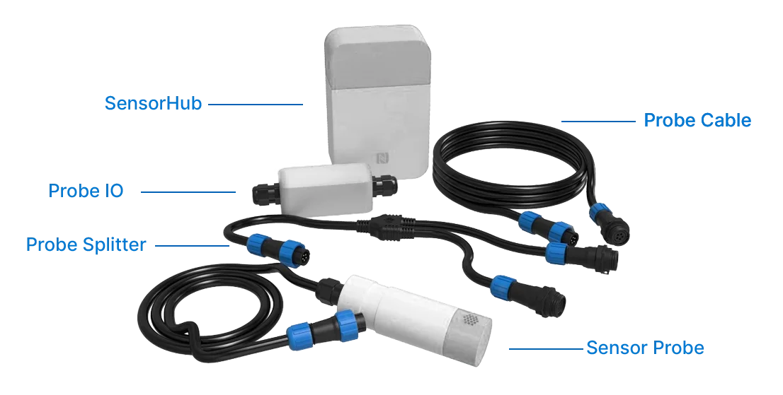 Figure 1: Sensor Hub ecosystem
WisNode Sensor Hub can be powered with batteries or a dedicated power adapter. It supports 2 to 4 battery types: ER18505 3.6 V 4000 mAh Li-SOCl2 NON-rechargeable lithium batteries which are NOT included upon purchase.
You can source the batteries locally or from one of the global electronics distributors:
Product Configuration
Before powering on the Sensor Hub, make sure that the sensor, Sensor Probe or Probe IO, and Sensor Hub are properly connected according to your setup.
Power On the Sensor Hub
Do not power the Sensor Hub before connecting the sensors to avoid damage to the device.
- Connect the Sensor Probe/Probe IO to the port of the RAK2560-Hub.
NOTE
If the Sensor Probe with Temperature, Humidity, and Pressure is used (RAK1901+RAK1902), there will be two temperature values in the WisToolBox. Due to the different accuracy of the temperature sensors, the values might be different.
- Use the power supply of your choice that is compatible with the device.
NOTE
Using the 12 VDC adapter provided with the Sensor Hub is recommended. You can also use 4 x EVE ER18505 3.6 V Lithium 4000 mAh battery and the voltage must be stable.
Device Configuration via WisToolBox
Accessing the Sensor Hub
- Download and install the WisToolBox app on your smartphone.
 Figure 1: WisToolBox App
 - Launch the app and make sure that the NFC is enabled on your mobile device and the Bluetooth is on. Tap SELECT DEVICE.
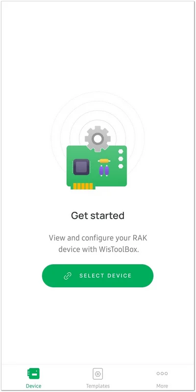 Figure 1: App home screen
 - Select the connection mode to pair the device.
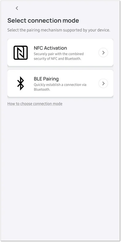 Figure 1: Connection mode
 - Select the Sensor Hub from the list of devices.
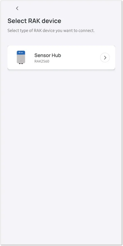 Figure 1: In-app list of devices
 - Pair your smartphone and the Sensor Hub by touching your phone to the N symbol on the front of the Hub and pressing CONNECT in the app. Retain the position of the smartphone touching the N symbol on the Hub and wait until the scan is done.
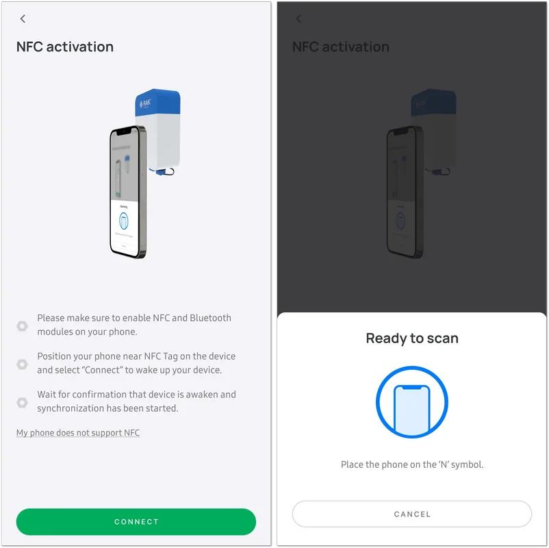 Figure 1: Pairing the Hub to your smartphone
 - Once the scan is done, a Scan successful message will appear.
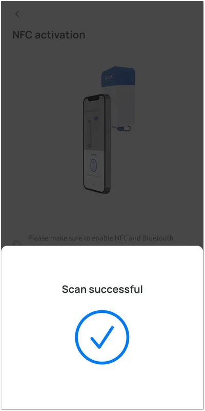 Figure 1: Scan successful
 - Automatic synchronization will start, wait until the process is complete.
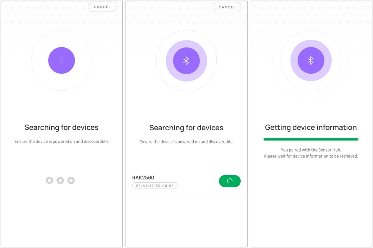 Figure 1: Device syncing
By default, the BLE advertising of the Sensor Hub is turned off automatically if no connection is established within 30 seconds of availability. Connect to the RAK device immediately after powering it on again.
Some Android smartphones require GPS enabled to permit connection to BLE. When GPS is enabled, no sensitive information is used or shared with the application.
Sensor Hub Info
When the data synchronization process is completed, you will see the SENSOR HUB INFO screen.
- HARDWARE: Product hardware version information
- FIRMWARE: Product software version information
- DEVEUI: EUI number of the device
- HARDWARE MODEL: Product model
- HUB SERIAL: The serial number of the device
- № SENSOR PROBES: Number of Sensor Probes currently connected to the device
- Documentation: A link to the RAK Documentation center
- Disconnect device: Break the connection between your smartphone and the Hub
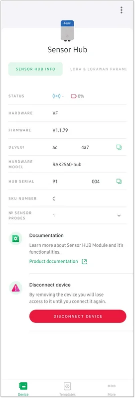 Figure 1: Sensor Hub Info
LoRa® and LoRaWAN® Parameters
In the LORA & LORAWAN PARAMETERS tab, you can set and see all the information needed so the device can join a network server of your choice.
- Configure the Join mode and Active region in Global settings.
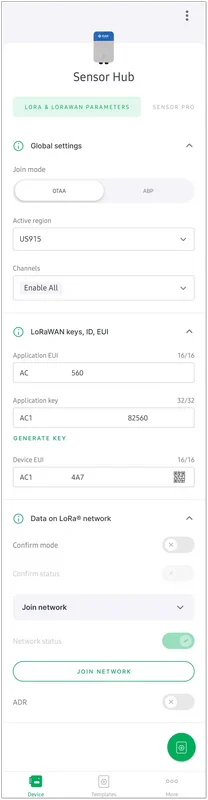 Figure 1: LoRa and LoRaWAN parameters screen
 - In the Active region menu, select the LoRaWAN band to be used.
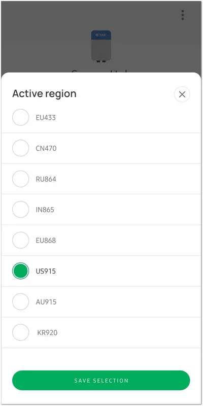 Figure 1: Active region list
 - You can see the Sensor Hub Application EUI, Application Key, and Device EUI that are needed to register the device in the network.
- You can turn on/off the Enable auto-join and ADR buttons according to your preferences.
- Tap the Join network button, and the device will be able to access the network, assuming you registered it properly.
Sensor Probe
- In the SENSOR PROBE screen, you can get all the information about the connected sensors.
- Probe ID: The ID that the Sensor Hub uses to identify the probe (until a reset is made). Value: 1~250
- Hardware: Probe's type version information
- Firmware: Probe's software version information
- Hardware model: Product model
- Probe type: RAK2560-Probe has two WisBlock slots that allow the mount of one or two WisBlock sensor modules in the mass production phase.
- Sensor count: The number of sensors in the probe.
The table shows the probe, module combination, and functionalities.
| Probe | Module Combination | Function | |||
|---|---|---|---|---|---|
| Temperature | Humidity | Barometric Pressure | 3-Axis Acceleration | ||
| A | RAK1901 | ✔ | ✔ | ||
| B | RAK1902 | ✔ | ✔ | ✔ | |
| C | RAK1904 | ✔ | |||
| AB | RAK1901+RAK1902 | ✔ | ✔ | ✔ | |
| AC | RAK1901+RAK1904 | ✔ | ✔ | ✔ | |
| BC | RAK1902+RAK1904 | ✔ | ✔ | ✔ | ✔ |
 Figure 1: Synchronization in progress
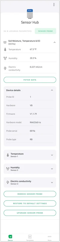 Figure 1: Sensor Probe screen
- Each sensor has a dropdown menu with the option to set some parameters as well.
 Figure 1: Sensor parameters
- Detailed sensor settings: Configure the parameter for sending the data.
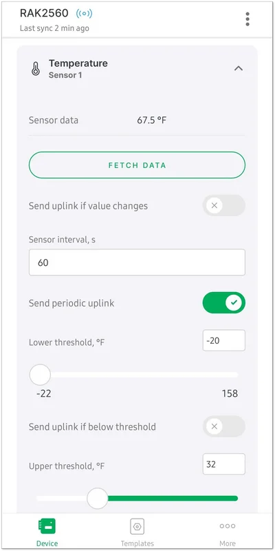 Figure 1: Detailed sensor settings
- Sensor data: The currently fetched data value
- Toggle button sensor data changes: Send data if there is any change in the sensor value
- Sensor interval(s): Payload sending interval in seconds (when periodic sensor rule is used). Limit: 60~86400 seconds
- Toggle button for periodic uplink: Sends data in the time interval configured
- Lower Threshold: Set up the lower value for the sending rules
- Upper Threshold: Set up the upper value for the sending rules
- The Sensor Probe sends data to the Sensor Hub according to established rules. Those rules are as follows:
| Name | Bit | Description |
|---|---|---|
| Alert | 0 | If below/above/between is triggered, the probe's sending interval will temporarily be changed to the min interval. |
| Below | 1 | If the below threshold is triggered, data will be sent. |
| Above | 2 | If the above threshold is triggered, data will be sent. |
| Periodic | 3 | Data follows the sensor's send interval. |
| Between | 4 | Data is between the below and above the threshold values. |
| Different | 5 | Data is different than the last data. |
Key = 0x03(Hex) = 0b00000011(Bin)
0x03 will enable the alert and the below rules. If below is triggered, data will be sent to the Sensor Hub.
- 0b00000001 = Alert Enable
- 0b00000010 = Below Enable
Key = 0x08(Hex) = 0b00001000(Bin)
0x08 will enable the periodic rule. The probe will send data according to the sensor's interval set.
- 0b00001000 = Periodic Enable
Configuring Sensor Hub for LoRaWAN Usage
To complete a LoRaWAN® deployment, you can register the Sensor Hub with a LoRaWAN Network Server (LNS). The following video provides an example of connecting the Sensor Hub to The Things Stack (TTN) and visualizing the received sensor data in Datacake using a WisGate Edge Gateway. You can use another supported LoRaWAN Network Server and application platform according to your deployment.
This tutorial uses the Weather Station solution as an example. The LoRaWAN network registration and data visualization workflow can be used as a reference for other Sensor Hub deployments.
Additional Resources
For additional setup examples and application-specific guidance, refer to the following resources.
Sensor Hub Solutions
For ready-to-deploy Sensor Hub configurations with supported sensors, refer to the WisNode Sensor Hub Solutions.
These solutions provide application-specific guidance for Sensor Hub, Sensor Probe, and Probe IO combinations.
Integrate Your Own Third-Party Sensor
If your sensor is not included in one of the predefined Sensor Hub Solutions, you can use the Generic Probe IO to integrate compatible third-party sensors.
Refer to the following guides for examples of configuring different sensor interfaces:


