RAK7201V2 WisNode Button 4K Quick Start Guide
Prerequisites
Package Inclusion
- 1 pc RAK7201V2 WisNode Button 4K
- 1 pc Micro USB cable
- 1 pc Sticker for attaching the button to a flat surface
Additional Requirements
- A LoRaWAN gateway in range
- Windows PC
Connect to the RAK7201V2
The RAK7201V2 can be configured using AT commands through the RAK Serial Port Tool. This Quick Start Guide covers the commands required for basic setup and LoRaWAN® network connection.
For the complete list of supported commands, refer to the RAK7201V2 AT Command Manual.
- Connect your RAK7201V2 WisNode Button 4K to your Windows machine using the provided Micro USB cable.
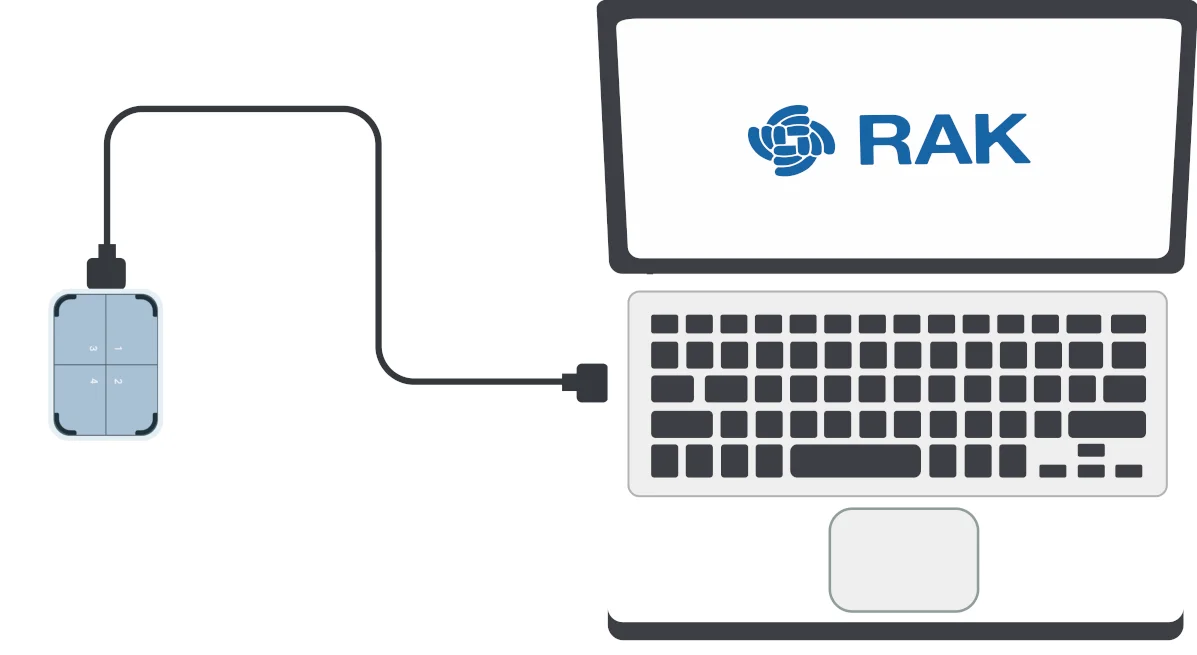 Figure 1: RAK7201V2 WisNode Button 4k to laptop connection
 - Open the RAK Serial Port Tool.
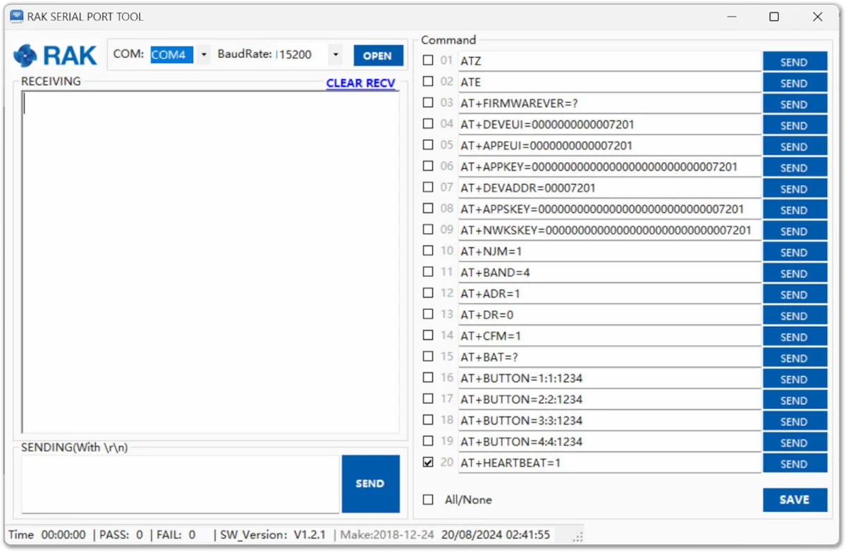 Figure 1: RAK Serial Port Tool
 - To choose the correct COM Port number for your device, go to your Device Manager by pressing the Windows key + R and type devmgmt.msc. You can also search for the Device Manager in the Start menu.
- Once opened, look for Ports (COM & LPT) and find the name USB-SERIAL CH340. The COM Port Number differs, and in this guide, it is COM4.
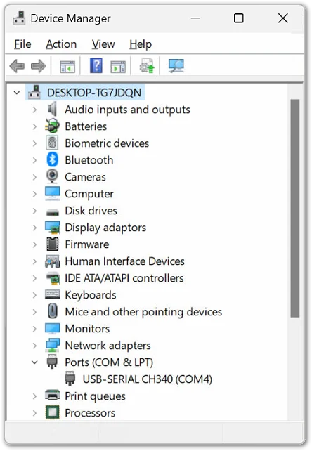 Figure 1: Device Manager
 - Choose the correct COM port number from the device manager and the correct baud rate, then click Open. The default baud rate of the WisNode Button 4K is 115200 bps.
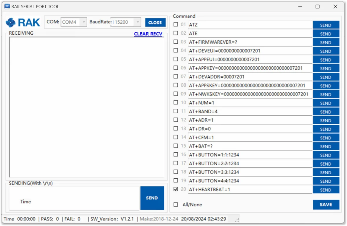 Figure 1: Correct COM port and baud rate are chosen
Connect to a LoRaWAN Network Server
The RAK7201V2 can connect to a compatible LoRaWAN Network Server (LNS) using either OTAA or ABP activation.
To connect the device successfully, make sure that the LoRaWAN region, activation mode, and credentials configured on the RAK7201V2 match the settings configured on the network server.
The following sections use the WisGate built-in Network Server as an example.
Connect to the WisGate Built-In Network Server
The following example uses the WisGateOS 2 Web UI and assumes that the gateway has already been configured to use its built-in LoRaWAN Network Server.
For instructions on configuring the built-in Network Server mode, refer to the user guide for your WisGate gateway.
Create an Application
- Login into the gateway via the Web UI and select the Application tab in the LoRa menu.
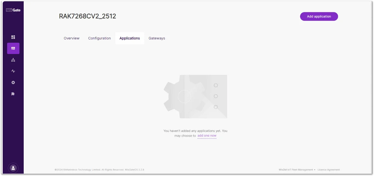 Figure 1: Application menu in the web UI of the gateway
 - Click the Add application button and fill out the Application name. Select Unified Application key as Application Type and use the Autogenerate button to generate an Application Key and Application EUI.
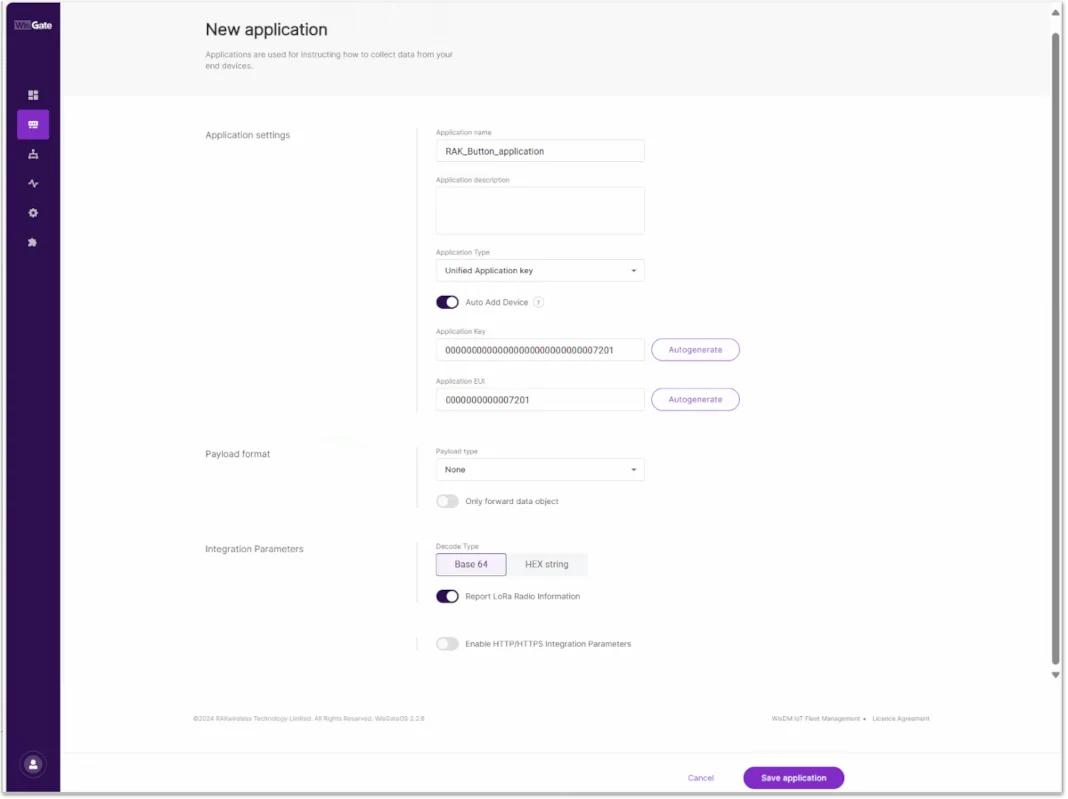 Figure 1: Creating an application
Add the RAK7201V2
-
In the created application, click on the End device tab and then the Add end device button.
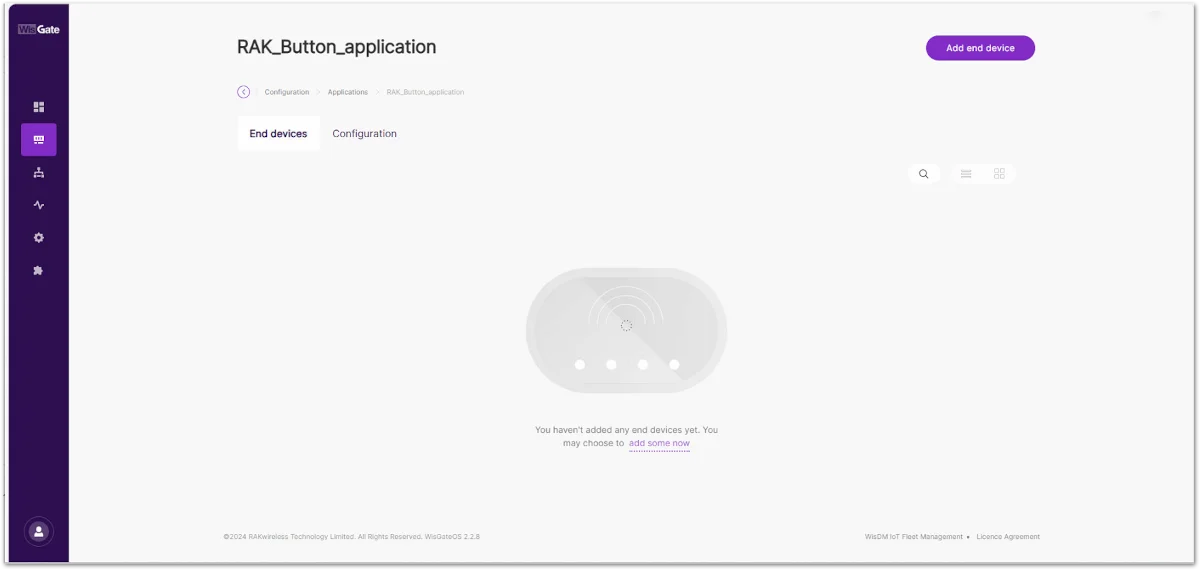 Figure 1: Application edit
 -
Select the Activation Mode for the end device. This guide uses OTAA as the example.
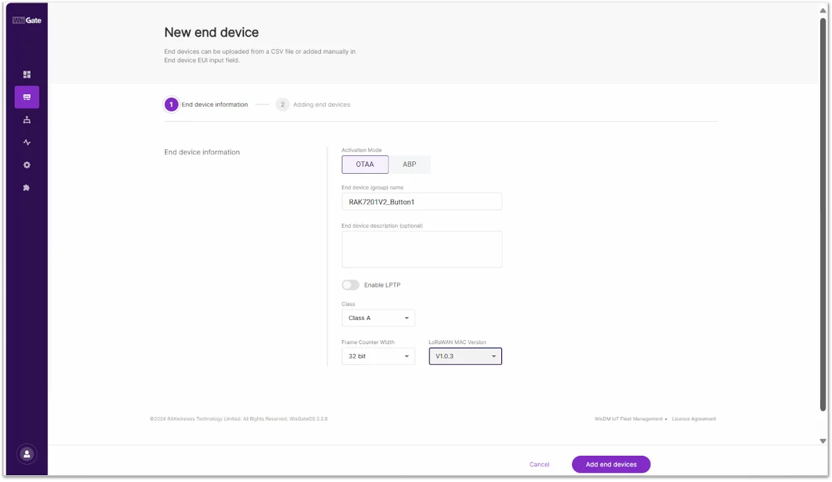 Figure 1: Adding the deviceNOTE
- OTAA uses the Application EUI and Application Key for network activation.
- ABP uses the End Device Address, Application Session Key, and Network Session Key.
Make sure the activation mode and corresponding parameters configured on the Network Server match those configured on the RAK7201V2.
-
Fill out the End device name and the LoRaWAN MAC Version (V1.0.3 is the correct one for RAK7201V2). Click on the Add end devices.
-
Input the End Device EUI of your device and then click Add to "End Devices list".
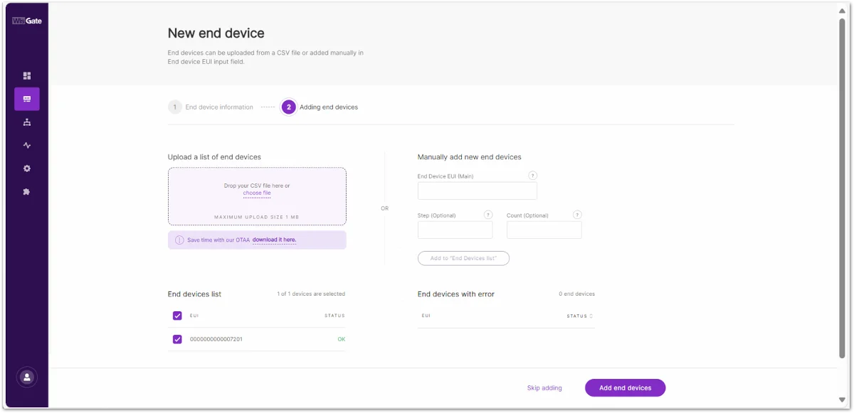 Figure 1: Configuring the device's setingsNOTE
If ABP is selected, configure the End Device Address (Main), Application Session Key, and Network Session Key according to the Network Server settings.
-
You will see the device in the End devices list and the Add end devices button will allow you to register your end device in the application.
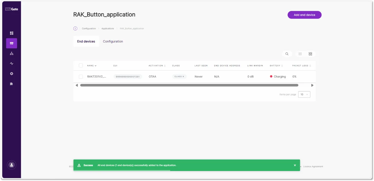 Figure 1: The device is registered
Configure the RAK7201V2 LoRaWAN Parameters
Configure the RAK7201V2 with parameters that match the settings on your LoRaWAN Network Server.
OTAA Mode
- To set the RAK7201V2 in OTAA work mode, the following AT commands must be executed in the RAK Serial Port Tool:
- Join Mode (OTAA)
AT+NJM=1
- Region (EU868 for this example)
AT+BAND=2
- Device EUI (on the sticker at the back of the device)
AT+DEVEUI=ac1f09fffexxxxxx
- Application EUI (from the application configuration created previously in the gateway)
AT+APPEUI=bf3112d69fxxxxxx
- Application Key (from the application configuration created previously in the gateway)
AT+APPKEY=ea980d6f2e42772550c66ec265xxxxxx
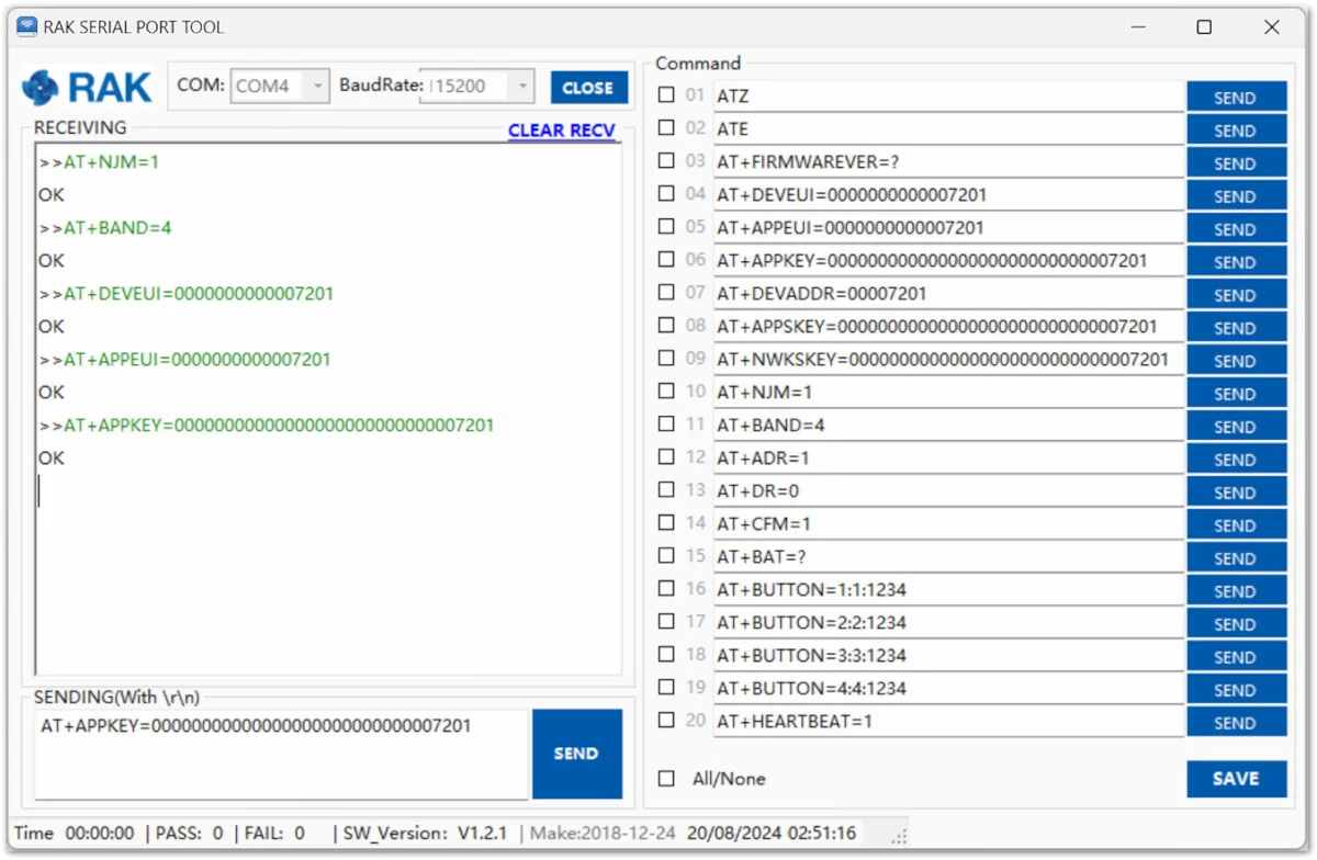 Figure 1: Configuring RAK7201V2 in OTAA mode
The Keys and EUIs shown here are just examples, use the ones generated by your system or corresponding to your device.
- To connect to the LoRaWAN Network after the configuration, the device must be restarted. The restart command is as follows:
ATZ
-
After restarting in OTAA mode, the RAK7201V2 attempts to join the configured LoRaWAN network.
NOTE-
If you need to manually initiate another join attempt, press and hold Button 1 for three seconds.
-
You can also use
AT+JOINto manually initiate a join through the serial interface during configuration or troubleshooting. For additional join parameters and options, refer to the RAK7201V2 AT Command Manual.
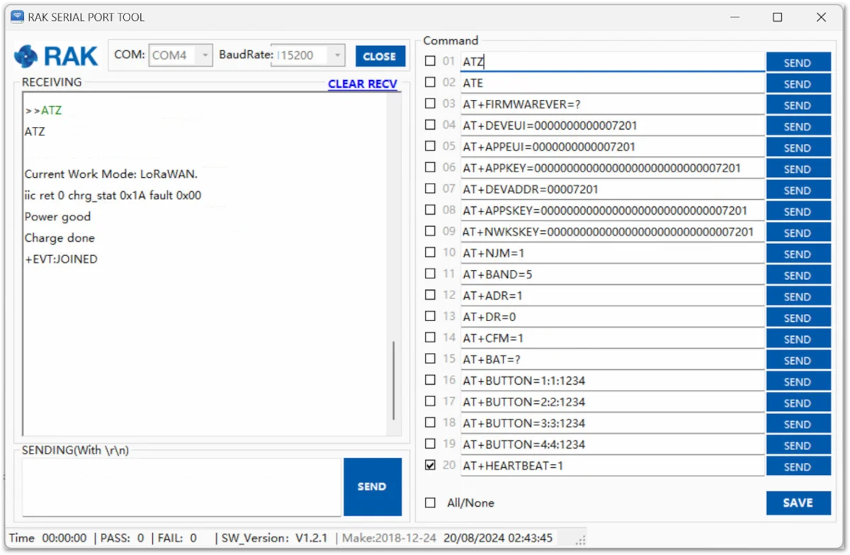 Figure 1: The device has restarted and connected to the LoRaWAN Network
 -
-
After the successful connection, the data obtained from pressing the buttons will be transmitted to the application server of the gateway.
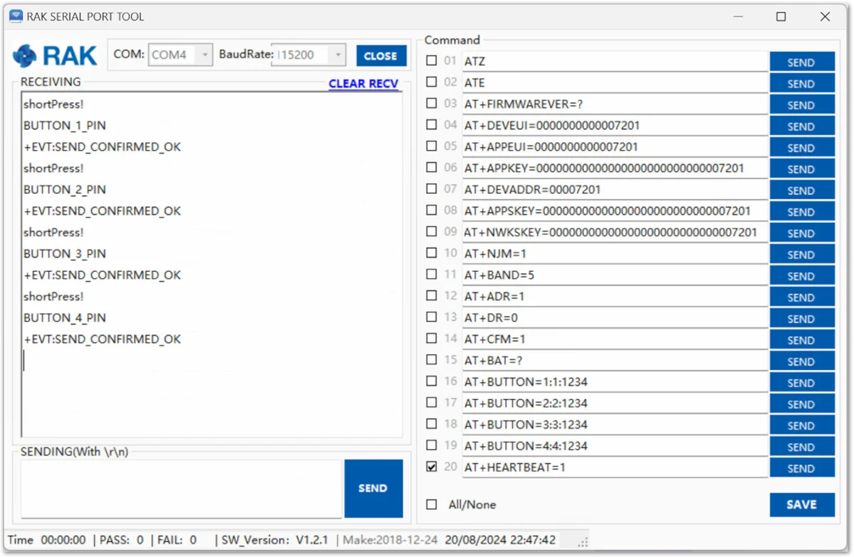 Figure 1: Successful operation of the buttons
 -
The received data from RAK7201V2 can be seen in the web UI of the gateway under Application > Device > Live Device Data.
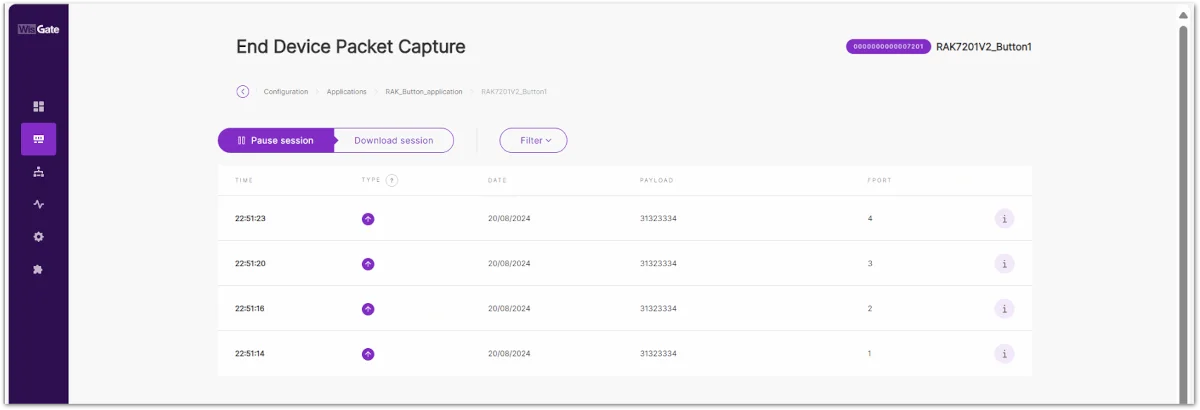 Figure 1: Received data
ABP Mode
When ABP is selected on the Network Server, configure the RAK7201V2 with the corresponding ABP parameters.
- To set the RAK7201V2 in ABP work mode, the following AT commands must be executed in the RAK Serial Port Tool:
- Join mode (ABP)
AT+NJM=0
- Device Address (from the device configuration created previously in the gateway)
AT+DEVADDR=00000001
- Application Session Key (from the device configuration created previously in the gateway)
AT+APPSKEY=bfb959106b004e5a32d8dde9fexxxxxx
- Network Session Key (from the device configuration created previously in the gateway)
AT+NWKSKEY=0a8139122e9e9011c049bcc575xxxxxx
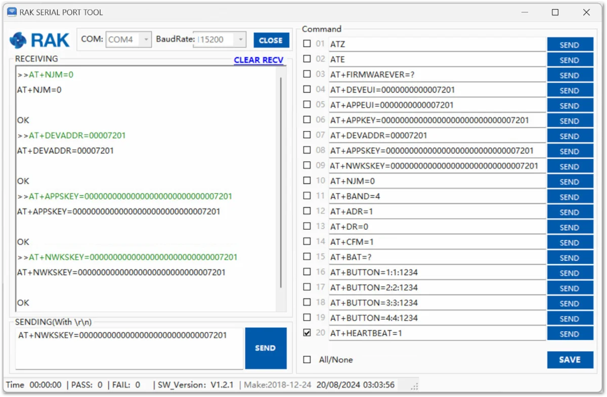 Figure 1: Configure the RAK7201V2 in ABP mode
The Keys and EUIs shown are just examples. Use the ones generated by your system or corresponding to your device.
- To connect to the LoRaWAN Network after the configuration, the device must be restarted. The restart command is as follows:
ATZ
-
After the restart, the device will be ready to send the information through the LoRaWAN Network.
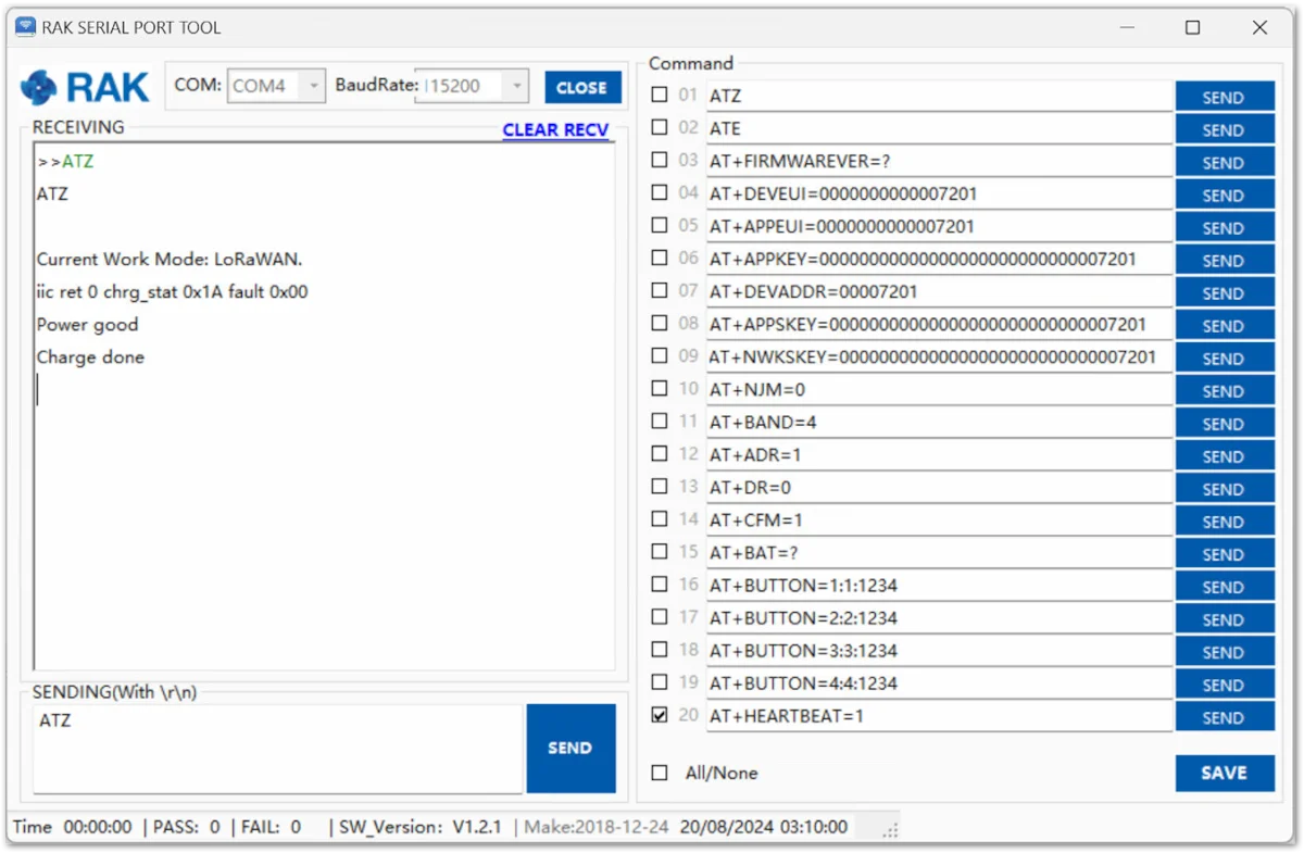 Figure 1: Configure the RAK7201V2 in ABP mode
There is no Join procedure in ABP mode. To be sure that the Button can send data, you need to press the buttons and see if you have uplinks in the Live Device Data field of the device in the gateway.
-
To test the ABP mode, press the buttons of the device.
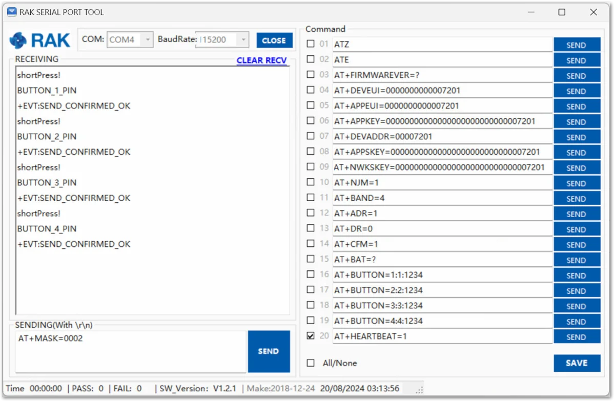 Figure 1: Testing the ABP mode
 -
The received data from RAK7201V2 can be seen in the web UI of the gateway under Application > Device > Live Device Data.
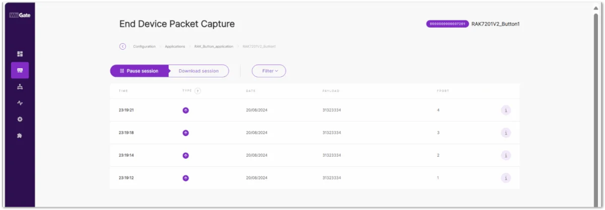 Figure 1: Received data
Other LoRaWAN Network Servers
The WisGate built-in Network Server is used as the configuration example in this guide. The RAK7201V2 can also connect to other compatible LoRaWAN Network Servers. When using another Network Server, make sure that the LoRaWAN region, activation mode, and corresponding credentials configured on the Network Server match those configured on the RAK7201V2.
Device Configuration
Customize the Data Sent
This section addresses the main functionality of the different keys (buttons) of the device.
The default payload data of the keys:
| Key | Data |
|---|---|
| Key 1 | A |
| Key 2 | B |
| Key 3 | C |
| Key 4 | D |
To customize the data sent by every button, follow the AT command:
AT+BUTTON=<button>:<port>:<data>
Where:
-
<button>: the configured key (range 1-4) -
<port>: the configured port number (range 1-223) -
<data>: the sent data (max length is 10 characters)
Example:
Change the data sent from the pressing of button 1 to HelloWorld using the command:
AT+BUTTON=1:1:HelloWorld
-
If the device is still transmitting data after a button press, additional button presses are ignored until the current transmission is complete.
-
Refer to the datasheet for the functions assigned to each button.
HeartBeat Functions
The HeartBeat is used to monitor the network connection and to send the battery level information of the RAK7201V2.
The device can send a HeartBeat packet according to the configured HeartBeat interval. The AT command for configuring the HeartBeat interval is as follows:
AT+HEARTBEAT=<interval>
Where:
- The interval range is 0-120 (in hours), 0 to turn off the function.
Example:
Set the HeartBeat to one hour using the command:
AT+HEARTBEAT=1
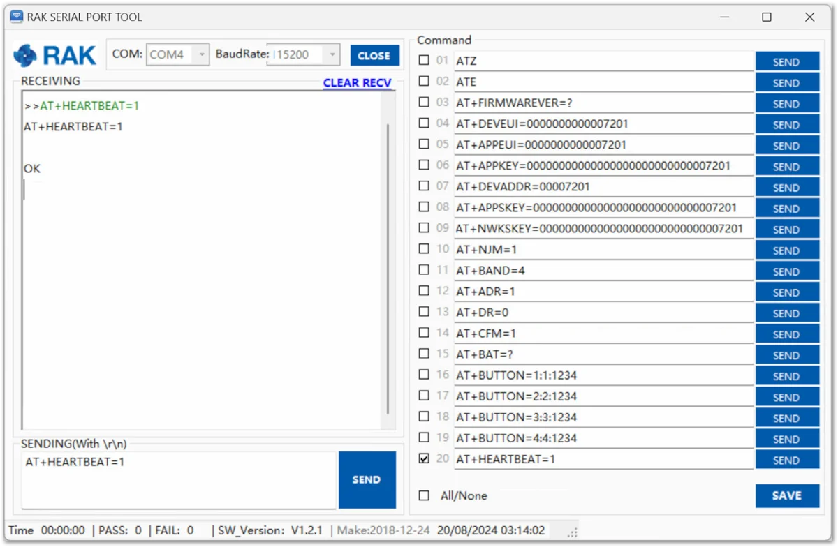 Figure 1: Set the HeartBeat interval
Heartbeat Payload
The HeartBeat message data format is as follows:
| Headers | Payload |
|---|---|
| 0X48 | Battery level in HEX |
The battery level is represented in percentage form in hexadecimal format.
Example:
If the payload message of the HeartBeat is 48 61, it represents 97% battery level.
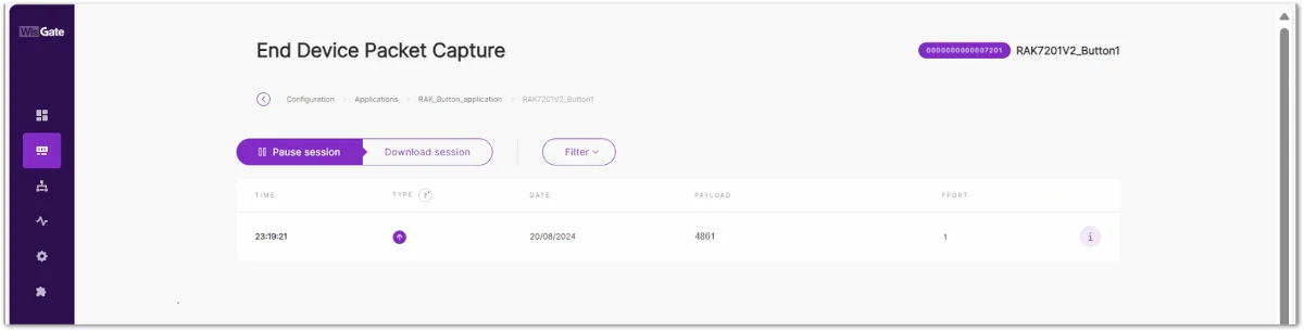 Figure 1: HeartBeat message in the Live Device Data
Low-Battery Warning
The device will automatically send a low-voltage alarm signal when the battery power is below 20% and again when it is below 10%.
Battery power warning signal:
| Battery Power | Warning Signal |
|---|---|
| Power is less than 20%. | 57 14 |
| Power is less than 10%. | 57 0a |
Device Restart
Two restart options are available:
- Using an AT command:
ATZ
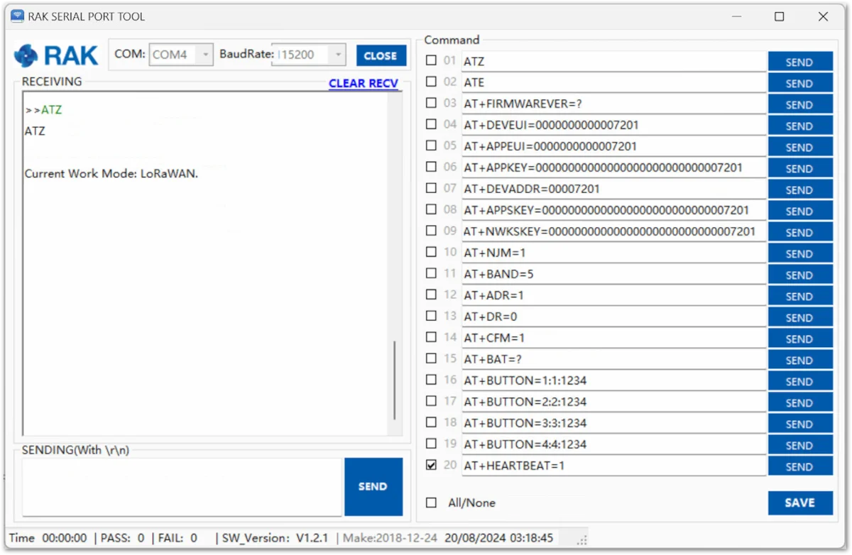 Figure 1: Restarting with an AT command
- Hold Key 2 for three (3) seconds. When held, the blue LED will stay lit. It will turn off when the device is restarted.
If the RAK7201V2 is configured in OTAA mode, it attempts to reconnect to the LoRaWAN network after restarting. The four blue LEDs flash clockwise while the device is attempting to join.
If the automatic join attempts are unsuccessful, the red LED on Button 4 flashes for one second to indicate a join failure.
To manually retry the network join, press and hold Button 1 for three seconds.
The AT+JOIN command can also be used to manually initiate a join when the device is connected to the serial interface.


