All-in-One. 5G NR Radio Configuration
This document describes the configuration of the integrated Next Generation Node B (gNB) for software version BaiBBU_QSS_1.1.x. It is a guide on how to configure the device after completing installation.
Overview
The All-in-One. 5G NR Next Generation Node B (gNB) is loaded with its own GUI for configuring its operating parameters. You can log in to the GUI either locally through the Local Maintenance Terminal (LMT), which is an Ethernet port, or remotely via an IP address.
After the gNB is powered on, configure the gNB to start services and access UEs, providing voice and data service. When configuring a newly installed gNB, we recommend you follow the flow that is shown in Figure 1.
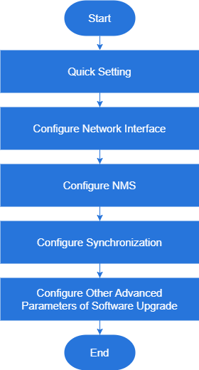 Figure 1: gNB Configuration Flow
Before configuring the device, data planning needs to be done first. The data to configure includes local parameters and network parameters. These parameters are either provided by the user or determined after negotiation with the customers.
The data to prepare includes network parameters, cell parameters, protocol parameters, software version, etc., as shown in Table 1.
Table 1: Data Planning
| Item | Parameter | Description |
|---|---|---|
| IP Address | OAM IP | OAM uses a separate IP address. |
| AMF IP | Planned by the customer. | |
| Cell | PLMN | Planned by the customer. |
| Parameters | TAC | Planned by the customer. |
| CellID | Planned by the customer. | |
| NREF(PointA, SSB) | Planned by the customer. | |
| Offset To PointA | Planned by the customer. | |
| Kssb | Planned by the customer. |
Login Client Web
Client Web Environmental Requirements
Table 2: Client Environmental Requirements
| Item | Description |
|---|---|
| CPU | Intel core above 1 GHz |
| Memory | At least 2G RAM |
| Hard disk | At least 100 MB of storage space |
| Operating system | Microsoft: Windows XP, Windows Vista, Windows 7 or Windows10 Mac: MacOS X 10.5 or above |
| Screen resolution | Above 1024 x 768 |
| Browser | Chrome 6 or higher |
Connect Client Web to Base Station
Connect the Ethernet interface of the computer to the network interface of the base station with the Ethernet cable.
Set Up Client Computer
Before logging into the Web client, the client computer’s IP address needs to be set up first so that the connection between the client and the server is possible. Take Windows 10 as an example:
- Open Control Panel from the Start Menu, then go to Network and Internet.
- Choose View network status and tasks, and then click Local Connectivity in the resulting window.
- Within the Status of Local Connectivity, click on Properties to open the Properties Local Connectivity pop-up window.
- Choose Internet Protocol Version (TCP/IPV4) and click Properties to access the window, as shown in Figure 2.
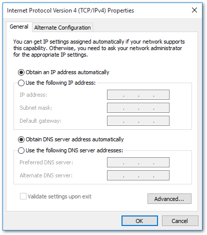 Figure 1: Internet Protocol Version4
Select either Obtain an IP address automatically or Use the following IP address:
- If Obtain an IP address automatically is chosen, proceed to step 7
- If Use the following IP address is selected, follow step 5 to step 7
In general, if the Obtain an IP address automatically setting fails, one needs to set up the IP address manually.
- Select Use the following IP address.
- Enter the IP address for the Operation and Maintenance (OAM) interface, along with the subnet mask and default gateway, then click OK to save the settings.
- IP address:
192.168.150.XXX(recommended XXX: 100~254).
Avoid using '192.168.150.7' since it's already assigned to the LAN interface of the base station.
- Subnet mask:
255.255.255.0 - Default gateway:
192.168.150.7
The default OAM IP address is 192.168.150.7/24. If the gNB configures IP address in other segments, you should configure according to your actual network environment.
- Open a command window and run the 'ping
192.168.150.XXXcommand to test the connection between the client computer and the server. If the ping command does not succeed, contact network engineers to verify network connectivity.
GUI Log In
- Open a web browser, and enter http://192.168.150.7, as shown in Figure 3.
This guide uses the initial IP address 192.168.150.7. If the IP address is changed, log in through the new IP address.
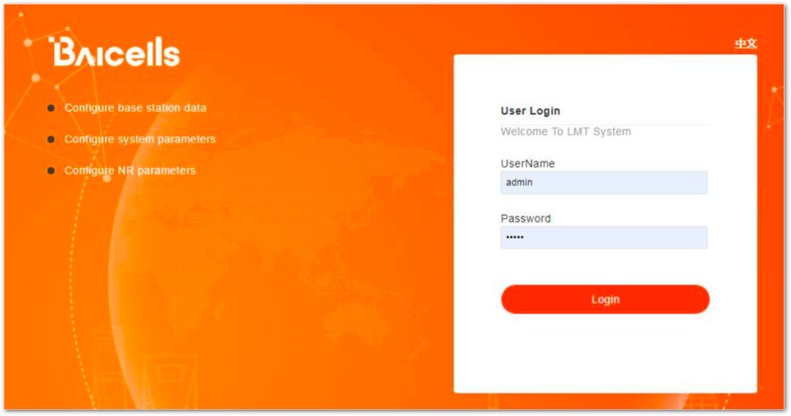 Figure 1: GUI Login
- Input user name, password, and click Login. The homepage is shown in Figure 4.
Default credentials:
username:new_user
password:gNB@2014
For security reasons, you should change the password after you first log in rather than leaving the default value.
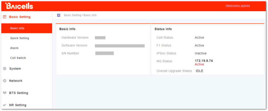 Figure 1: GUI Homepage
The menus and information may vary by product type or software version.
The homepage displays the navigation pane on the left, and shows the window for the first menu: Basic Setting and then Basic Info. This window is like a dashboard for the device.
- Basic info: shows information such as the hardware version, software version, and serial number, and many more.
- Status info: shows the status information of Cell, F1, IPSec, NG and the Overall Upgrade. If the Cell status, F1 status, and NG status all show Active, it indicates that the cell is normal.
- IPsec status: is an indicator which is configured according to the actual network environment.
- Overall Upgrade Status: is the upgrade status indicator.
For the second menu: Basic Setting and then Alarm is the menu displays the current alarms, as shown in Figure 5.
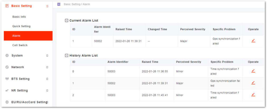 Figure 1: Current Alarm
Basic Setting
The quick settings determine important RF parameters. These parameters need to be planned in advance during the network planning stage.
- In the navigation column in the left, select Basic Setting and then Quick Setting to enter the quick setting page, as shown in Figure 6.
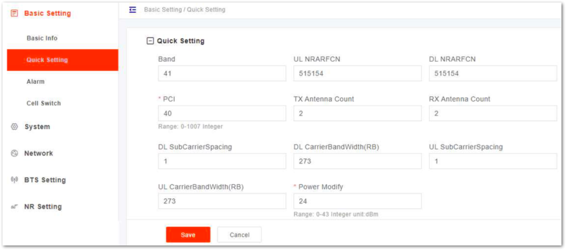 Figure 1: Quick Setting
- Input quick setting parameters, the parameter descriptions are given in Table 3.
Table 3: Quick Setting Parameter Description
| Parameter | Description |
|---|---|
| Band | Operation frequency band, currently includes N48, N78 |
| UL NRARFCN | Uplink NR-ARFCN |
| DL NRARFCN | Downlink NR-ARFCN |
| PCI | Physical Cell ID (PCI) is allocated by the operator. It is an essential Layer 1 cell identity for each cell site in the network. Planning PCIs is crucial for QoS. Range from 0 to 1007. |
| TX Antenna Count | The number of transmitting antennas. The gNB supports up to 2 TX antenna. |
| RX Antenna Count | The number of receiving antennas. The gNB supports up to 2 RX antennas. |
| DL SubCarrierSpacing | Downlink subcarrier spacing The gNB supports 30 kHz in this version. |
| DL CarrierBandWidth(RB) | Downlink carrier bandwidth |
| UL SubCarrierSpacing | Uplink subcarrier spacing The gNB supports 30 kHz in this version. |
| UL CarrierBandWidth(RB) | Uplink carrier bandwidth |
| Power Modify | Transmitted power Range from 0 to 43 dBm. |
- Click Save to complete the quick settings for the gNB.
System Parameter Configuration
NTP Configuration
This page includes the time zone and the NTP configuration, which are configured according to actual needs. If NTP is used by the gNB as an external clock source, up to five NTP servers are supported, one for master NTP service and the others for backup.
- In the navigation column on the left, select System and then NTP to enter the NTP setting page, as shown in Figure 7. The page displays the current date and time.
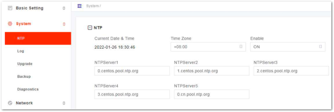 Figure 1: NTP Server Setting
- Select the Time Zone where the gNB is located.
- Select whether or not to enable the NTP function.
- Input NTP server parameters. The parameter description is shown in Table 4.
Table 4: NTP Server Parameter Description
| Parameter | Description |
|---|---|
| NTPServer1 | Domain name or IP address of the primary NTP server. Must be consistent with the other end. |
| NTPServer2 | Domain name or IP address of a secondary NTP server. Must be consistent with the other end. |
| NTPServer3 | Domain name or IP address of a secondary NTP server. Must be consistent with the other end. |
| NTPServer4 | Domain name or IP address of a secondary NTP server. Must be consistent with the other end. |
| NTPServer5 | Domain name or IP address of a secondary NTP server. Must be consistent with the other end. |
- Click Save to complete the NTP server configuration.
Log Configuration
In the navigation column on the left, select System and then Log to enter the log level setting page, as shown in Figure 8.
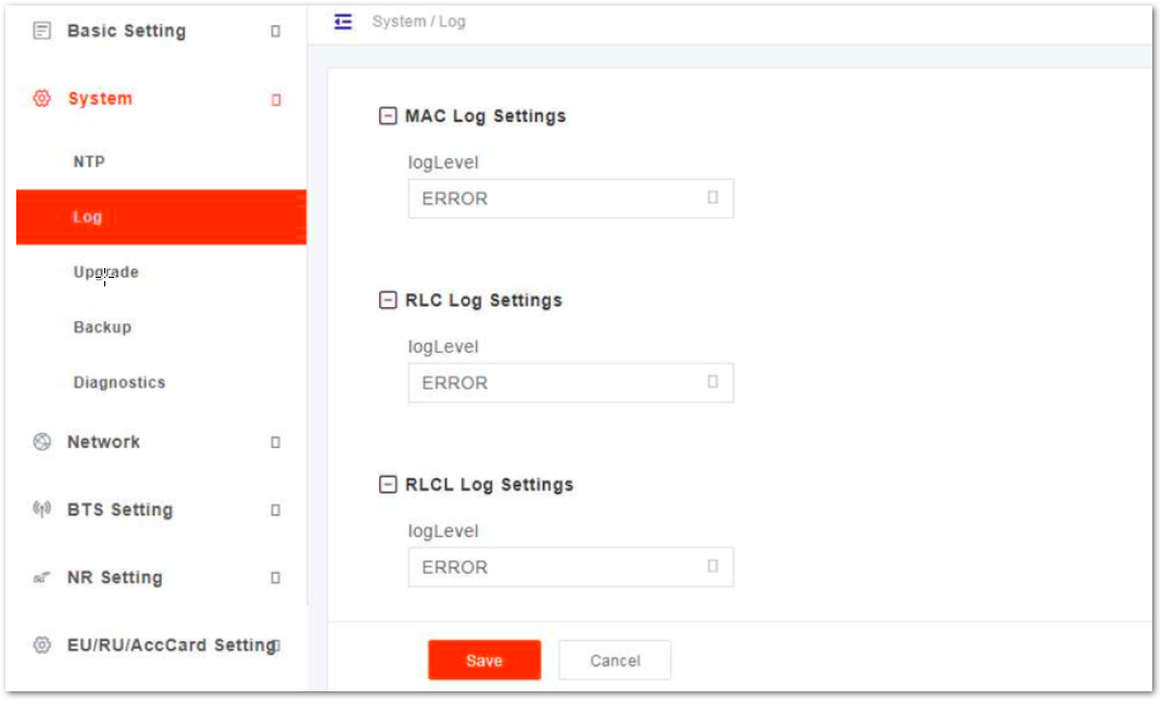 Figure 1: Log Level Setting
The gNB supports the log level setting for Media Access Control (MAC) log, Radio Link Control (RLC) log and RLCL.
The following levels are supported:
- FATAL
- ERROR
- INFO
- BRIEF
- DETAILED
- DETAILED ALL
Software Upgrade
When the preset version does not meet the actual need, the software version needs to be updated to the latest version. The system supports firmware version upgrade and rollback, configuration upgrade, etc.
Firmware upgrade may lead to the damage of the gNB file, contact the support engineer before upgrading. If necessary, the vendor will provide the technical support.
Firmware Upgrade
- In the navigation column on the left, select System and then Upgrade to enter the upgrade page, as shown in Figure 9.
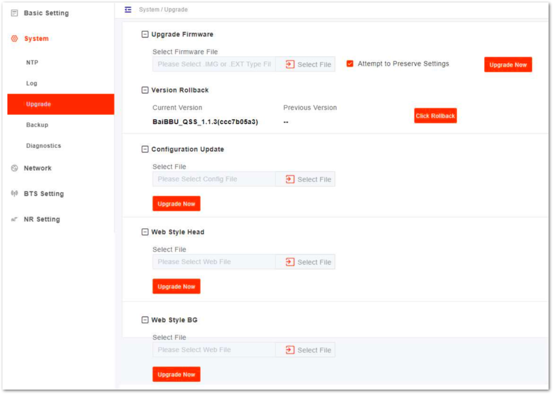 Figure 1: Upgrade
- Get new version of firmware file and save it to your local computer.
- Select whether or not to preserve the current settings.
- Click Select File to select the firmware file to upload.
- Check whether the software version is correct again and then click Update Now.
- In the pop-up window click PROCEED.
- In step 4, the file type is
.EXT. - In the Basic Setting > Basic Info page, the upgraded version displayed should match the version from step 2.
Rollback
Only one rollback operation is allowed for each upgrade. By permission of the BBU, the software can roll back to the version before upgrading. After the rollback, a new rollback will not be permitted until an upgrade has taken place. If the previous version is -, there is no software version for rollback.
- Click Click Rollback.
- In the pop-up window, click OK. Wait for about three minutes until the base station will reboot completely. In the Basic Setting > Basic Info page, the version after rollback will be displayed in the Software Version.
Configuration Upgrade
- Click Select File to select the configuration file to upload.
- Then click Update Now
Other file will also upgrade by following these steps.
Backup
In the navigation column on the left, select System and then Backup to enter the backup page, as shown in Figure 10.
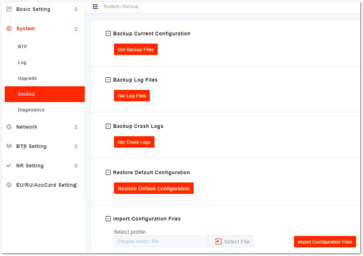 Figure 1: System Backup
Backup Current Configuration
- Click Get Backup Files.
- In the pop-up download dialog box, select the file path to save the current configuration file to the local computer.
Backup Log Files
- Click Get Backup Files.
- In the pop-up download dialog box, select the file path to save the log files to the local computer.
Backup Crash Logs
- Click Get Backup Files.
- In the pop-up download dialog box, select the file path to save the crash log files to the local computer.
Restore Default Configuration
After the restore operation, the gNB will reboot immediately. Be careful when using the Restore Default Configuration feature. It will disrupt the current service.
- Click Restore Default Configuration.
- In the pop-up download dialog box click OK, the base station will reboot immediately.
Wait for about three minutes, the base station will reboot completely.
Import Configuration File
- Click Select File to select the configuration file from the local computer.
- Click Upload to import the configuration file.
- Click Import Configurations Files to import the configuration file.
Diagnostics
The gNB supports the tcpdump command to collect and analyze network data.
- In the navigation column on the left, select System and then Diagnostics to enter the diagnostics page, as shown in Figure 11.
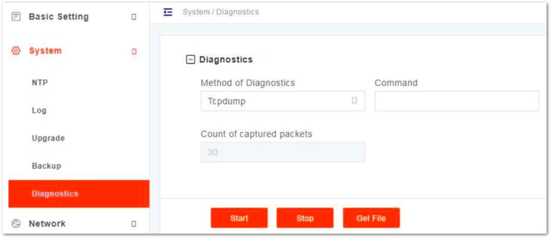 Figure 1: Diagnostics
- Input network diagnostics parameters, the parameter descriptions are shown in Table 5.
Table 5: Parameter Description of tcpdump Command
| Parameter | Description |
|---|---|
| Method of Diagnostics | Tcpdump |
| Command | Tcpdump command |
| Count of captured packets | The number of captured packets. |
- Click Start to run the tcpdump command.
- Click Stop to stop running.
- Click Get File to download the file to the local computer.
Reboot
The reboot operation will interrupt the current service, so be careful when performing this operation.
- On the left navigation, select Reboot to enter the reboot window.
- Click Reboot, and the gNB will restart immediately.
Network Interface Configuration
Configuration of the network interface includes WAN, VLAN, IPsec, Differentiated Services Code Point (DSCP) and static routes.
WAN/LAN Interface Configuration
The WAN interface is an external communication portal (Internet connection) to the core network. The only option for the Interface name field is WAN. The WAN interface supports the configuration of multiple VLANs.
- On the navigation column on the left, select Network and then WAN/VLAN to enter the WAN interface and VLAN configuration page, as shown in Figure 12.
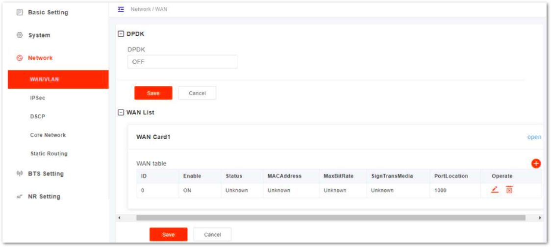 Figure 1: Configure WAN/VLAN
In this software version, DPDK is not supported.
- Click
+to add WAN card, as shown in Figure 13.
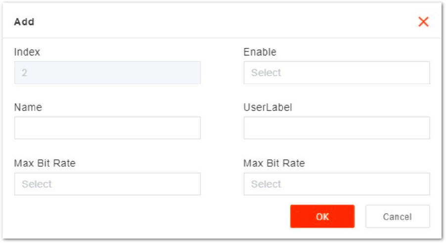 Figure 1: Add WAN Card
- Input parameters of the WAN card, as shown in Table 6.
Table 6: WAN Card Parameter Description
| Parameter | Description |
|---|---|
| Index | The Index is generated automatically. |
| Enable | Enables or disables the port. |
| Name | Name |
| User Label | User Label |
| Max Bit Rate | Select maximum bit rate of the port from the drop-down list. The units are in Mbit/s
|
| Mode | Select the working mode of the port from the drop-down list:
|
- Click Open to display the attribute parameters of the WAN interface, as shown in Figure 14.
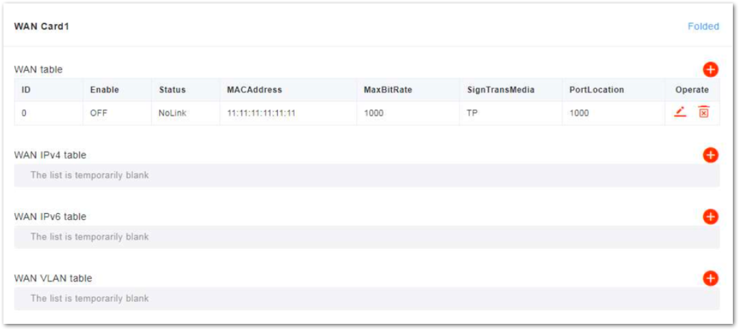 Figure 1: Configure WAN Interface Attribute
- Configure IPv4, IPv6, or VLAN parameters based on the actual network deployment.
• IPv4
Click + on WAN IPv4 table zone to display the IPv4 configuration parameters, as shown in Figure 15.
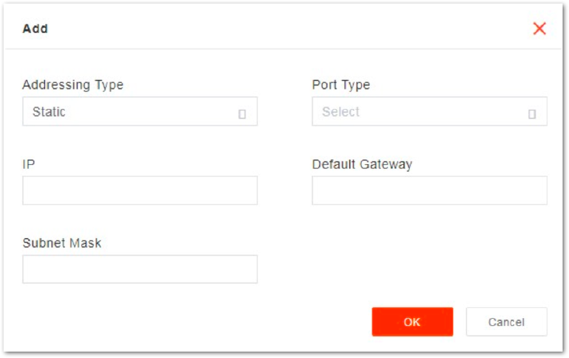 Figure 1: IPv4 Configuration Parameters
The description of IPv4 configuration parameters is shown in Table 7.
Table 7: IPv4 Parameter Description
| Parameter | Description |
|---|---|
| Addressing Type | The interface protocol used by the WAN interface. It includes:
|
| Port Type | WAN port type. According to the network plan, specify the usage of the port.
|
| IP | When Addressing Type is set to Static, the parameter displays. |
| Default Gateway | When Addressing Type is set to Static, the parameter displays. |
| Subnet Mask | When Addressing Type is set to Static, the parameter displays. |
• IPv6
Click + on WAN IPv6 table zone to display the IPv6 configuration parameters, as shown in Figure 16.
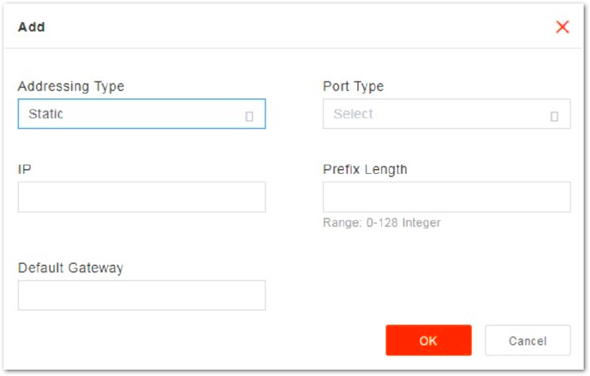 Figure 1: IPv6 Configuration Parameters
The description of IPv6 configuration parameters is shown in Table 8.
Table 8: IPv6 Parameter Description
| Parameter | Description |
|---|---|
| Addressing Type | The interface protocol used by the WAN interface, includes:
|
| Port Type | WAN port type. According to the network plan, specify the usage of the port.
|
| IP | When Addressing Type is set to Static, the parameter displays. The IP address of the WAN interface. |
| Default Gateway | When Addressing Type is set to Static, the parameter displays. The IP address of the default gateway. |
| Subnet Mask | When Addressing Type is set to Static, the parameter displays. The Subnet mask address of the IP address. |
• VLAN
Click + on WAN VLAN table zone to display the VLAN configuration parameters, as shown in Figure 17.
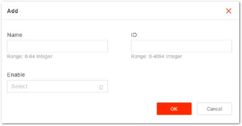 Figure 1: VLAN Configuration Parameters
The description of VLAN configuration parameters is shown in Table 9.
Table 9: VLAN Parameter Description
| Parameter | Description |
|---|---|
| Name | VLAN name |
| ID | VLAN ID |
| Enable | Enables or disables VLAN
|
- Click Save to complete the WAN and VLAN configuration.
IPSec Configuration
The security gateway (SeGW) can provide a security protocol at the network layer to ensure safe message transmission. If the operator has deployed the security gateway, the gNB needs to enable the IPsec function accordingly to establish a safe VPN channel between the gNB and the SeGW.
The gNB disables the IPsec by default.
- Select Network and then IPsec to enter the IPsec configuration page, as shown in Figure 18.
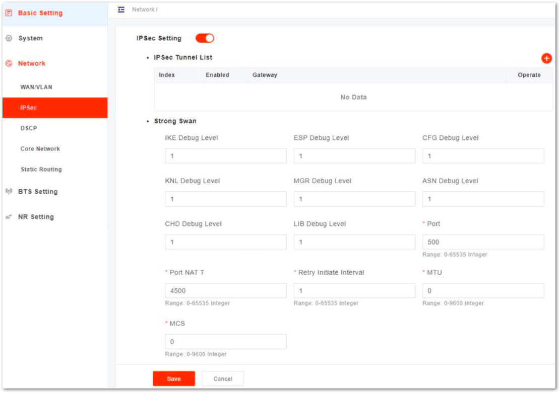 Figure 1: Configure IPsec
- Select enable or disable the IPsec function. The IPsec function is enabled by default.
- If the IPsec function is enabled, click
+to add a IPsec tunnel. - In IPsec Tunnel List area, click Edit to enter the edit dialog box, as shown in Figure 19.
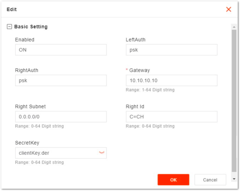 Figure 1: Edit IPsec Tunnel
The description of basic parameters is shown in Table 10.
Table 10: IPsec Tunnel Basic Parameter Description
| Parameter | Description |
|---|---|
| Enabled | Enables or disables this IPsec tunnel. |
| LeftAuth | Local authentication type of the IPsec. Must be consistent with the security gateway side.
|
| RightAuth | Peer authentication type of the IPsec. Must be consistent with the security gateway side.
|
| Gateway | The security gateway (IPsec server) IP address. Make sure the IP address entered here matches the actual IP address on the security gateway side. |
| Right Subnet | IP address of the remote subnet, which must be consistent with the security gateway side. Message within this address range will be packed as a tunnel. |
| Right Id | Identification of the server end (0-48 digits string). It must be consistent with the security gateway side. |
It is highly recommended that for the Advanced Setting fields you use the default values. Improper changes may lead to system malfunctions.
Changes in the LeftAuth and RightAuth values are not recommended.
The Advanced Setting fields become particularly important to network operations as areas become denser with users.
The description of advanced parameters is shown in Table 11.
Table 11: Advanced Parameter Description of IPsec Tunnel Mode
| Parameter | Description |
|---|---|
| Left Id | The Identification of the client end (0-48 digit string). It must be consistent with the security gateway side. If there is no security gateway left identifier, leave this field empty. |
| LeftCert | If set LeftAuth to Pubkey, the parameter needs to be set. Certificate name. On this version is clientCert.derpsk. |
| LeftSourceIp | The Virtual address allocation assigned by the system. If absent, use the local IP address |
| Left Subnet | The IP address of the local subnet. |
| Fragmentation | The type of fragmentation
|
| IKE Encryption | The Internet Key Exchange (IKE) encryption method. IKE is a protocol used to ensure security for virtual private network (VPN) negotiation and remote host or network access.
|
| IKE DH Group | IKE Diffie-Hellman (DF) groups set key size and strength used in the key exchange process. It enable devices to agree on a secret key without direct transmission while enhancing security in the IKE protocol.
|
| IKE Authentication | Authentication algorithm
|
| ESP Encryption | Encapsulating Security Payload (ESP) – member of the IPsec protocol suite that provides origin authenticity, integrity, and confidentiality protection of packets.
|
| ESP DH Group | ESP Diffie-Hellman (DF) groups determine key size and strength for securing communication in the IPSec protocol. It enhancesencryption in a concise manner.
|
| ESP Authentication | ESP Authentication algorithm
|
| Key Life | IPsec security association (SA) renegotiation time. Format: Seconds, Minutes, Hours or Days. |
| IKELifeTime | IKE security association renegotiation time. Format: Seconds, Minutes, Hours or Days. |
| RekeyMargin | Renegotiation time before the expiry of IKE life time (negotiate the IKE security association time before the expiry of IKE life time). Format: Seconds, Minutes, Hours or Days. |
| Dpdaction | DPD stands for dead peer detection (DPD) protocol. Determines what action to take when a gateway exception occurs.
|
| Dpddelay | Time interval for sending the DPD detection message. Format: Seconds, Minutes, Hours or Days. |
| Left Interface | The interface on the gNB side. |
- Input strong WAN configuration parameters, as shown in Table 12.
Table 12: Strong WAN Parameter Description
| Parameter | Description |
|---|---|
| IKE Debug Level | IKE debug level Range: -1,0,1,2,3,4 |
| ESP Debug Level | ESP debug level Range: -1,0,1,2,3,4 |
| CFG Debug Level | CFG debug level Range: -1,0,1,2,3,4 |
| KNL Debug Level | KNL debug level Range: -1,0,1,2,3,4 |
| MGR Debug Level | MGR debug level Range: -1,0,1,2,3,4 |
| ASN Debug Level | ASN debug level Range: -1,0,1,2,3,4 |
| CHD Debug Level | CHD debug level Range: -1,0,1,2,3,4 |
| LIB Debug Level | LIB debug level Range: -1,0,1,2,3,4 |
| Port | Port number |
| Port NAT T | NAT T port number |
| Retry Initiate Interval | Retry initiate interval |
| MTU | Maximum transmission unit The maximum value is 9600 bytes. |
| MCS | MCS Range: 0 9600 bytes |
- Click Save to complete the IPsec configuration.
DSCP Configuration
- In the navigation column on the left, select Network and then DSCP to enter the DSCP configuration page, as shown in Figure 20.
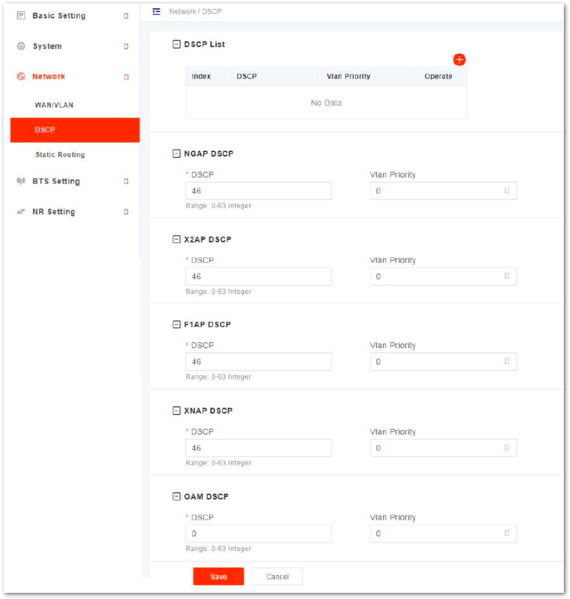 Figure 1: Configure DSCP
- Click
+to display DSCP adding window as shown in Figure 21.
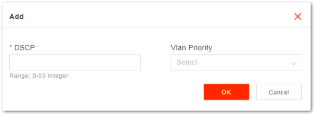 Figure 1: Add a DSCP
- Input DSCP parameters, as shown in Table 13.
Table 13: Strong WAN Parameter Description
| Parameter | Description |
|---|---|
| DSCP | DSCP code is used to differentiate the priority level. Range from 0 to 63 (integer). |
| VLAN Priority | Vlan priority Range from 0 to 7 (integer). |
- Click Save to complete the DSCP setting.
On the lower of the page, you can specify DSCP value and VLAN priority for NGAP, X2AP, F1AP, XNAP and OAM.
Core Network Configuration
This version does not support this menu.
Static Routing Configuration
This function is for users that need to configure static routing.
- In the navigation column on the left, select Network and then Static Routing to enter the static routing configuration page, as shown in Figure 22.
 Figure 1: Configure Static Routing
This page displays the static route list.
- Click
+to display static configuration parameters, as shown in Figure 23.
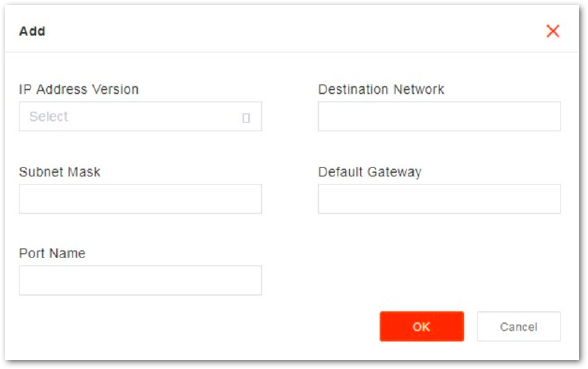 Figure 1: Add Static Route
Input the configuration parameters of the static route, which are given in Table 14.
Table 14: Static Route Parameter Description
| Parameter | Description |
|---|---|
| IP Address Version | Profit
|
| Port Name | Port Name |
| Destination Network | The destination IP address. |
| Subnet Mask | The subnet mask of target IP address. |
| Default Gateway | The gateway IP address of target IP address. |
- Click Save to complete the static route configuration.
For the Destination Network, the target IP address must reachable from the original IP address of the WAN interface or VLAN source port.
BTS Parameter Configuration
Management Server Configuration
For the Network Management System (NMS), an operator can configure their own management server.
After configuring NMS, you can log in to NMS to check whether the gNBs have been added or not. Once added, the gNB can be configured and managed on the NMS.
- In the left navigation column, select BTS Setting and then Management Server as shown in Figure 24.
 Figure 1: Configure Network Management Server
- Input the network management parameters, whose descriptions are given in Table 15.
Table 15: Network Management Server Parameter Description
| Parameter | Description |
|---|---|
| Management Server | The URL of the management server. Example: http://172.17.9.82:8080/smallcell/AcsService When the NMS is hosted in the cloud, the domain name is also supported. |
| Period | The period of the gNB and the NMS, range from 1 to 65535. The units are in minutes. |
| OMC Vendor | The vendor that provides the NMS. |
- Click Save to complete the NMS configuration.
Performance Management
- In the left navigation column, select BTS Setting and then Performance Management as shown in Figure 25.
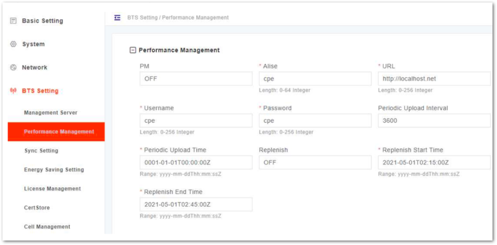 Figure 1: Performance Management
- Input the performance management parameters, whose descriptions are given in in Table 16.
Table 16: Performance Management Parameter Description
| Parameter | Description |
|---|---|
| PM | Enables or disables performance management.
|
| Alise | Alise |
| URL | http://localhost.net |
| Username | Username |
| Password | Password |
| Periodic Upload Interval | Periodic upload interval |
| Periodic Upload Time | Periodic upload time |
| Replenish | Enables or disables replenish |
| Replenish Start Time | Replenish start time |
| Replenish End Time | Replenish end time |
- Click Save to complete the performance management configuration.
Synchronization Configuration
5G technology standards specify time synchronization requirements between adjacent gNBs. Synchronization between gNBs can help reduce interference, optimize bandwidth utilization, and improve network capacity.
This gNB supports GPS synchronization in this version.
- In the left navigation column, select BTS Setting and then Sync Setting to enter the synchronization configuration page, as shown in Figure 26.
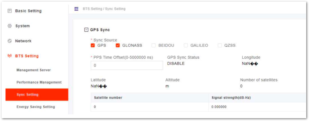 Figure 1: Synchronization Mode Setting
- Select GPS source.
- GPS
- GLONASS
- BEIDOU
- GALILEO
- QZSS
- Input PPS time offset. Range is from 0 to 5,000,000 ns.
- Click Save to complete the synchronization setting.
Energy Saving Configuration
In this software version, energy saving is not be supported.
License Management
The License Management menu may be used to import license files for optional features, such as regulatory certificates of authorization to operate. When imported, the files are stored in the gNB memory and shown in the License List area of this window.
- In the left navigation column, select BTS Setting and then License Management to enter the License Management page, as shown in Figure 27.
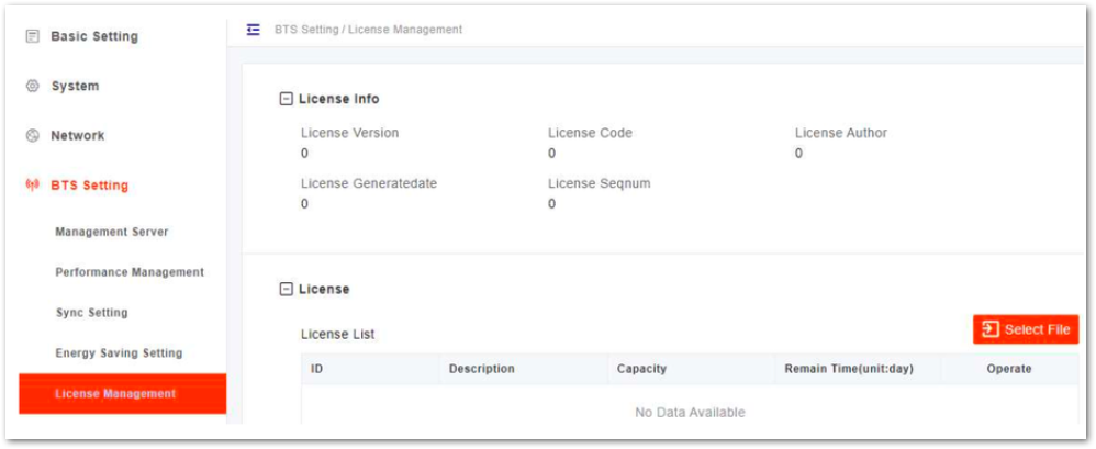 Figure 1: License Management
Remain Time Indicates the remaining days of the License. If 0 is displayed, apply for a License and upload it to update it as soon as possible. Otherwise, the cell cannot be activated or user access is restricted.
- Select the License file from the local computer.
- Click Import License to upload the license file to the gNB. After the License file is uploaded, it will display in the license list.
Certificate Store
If the gNB wants to achieve some functions which need some authentication, this page supports to upload, view, export, or delete these certificates.
For IPsec private setting, only the .der files need to be uploaded. The .bin files are generated automatically and do not need to be uploaded.
This version does not support the menu.
Cell Management
In the left navigation column, select BTS Setting and then Device Topology to enter the device topology page, as shown in Figure 28.
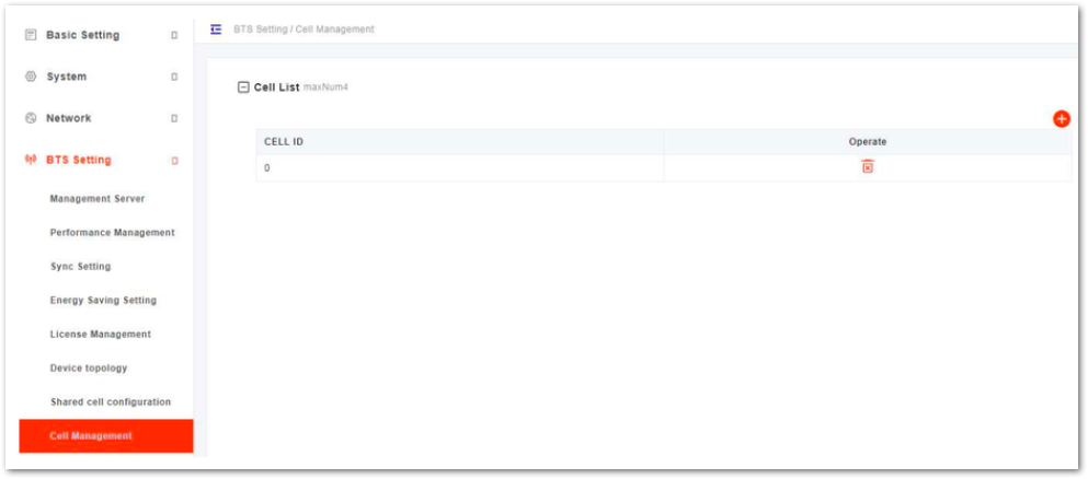 Figure 1: Cell Management
This version supports one cell.
NR Parameter Configuration
LTE Neighbor Frequency and Cell Configuration
- In the left navigation column, select NR Setting and then LTE Freq/Cell to enter the LTE neighbor frequency and cell configuration page, as shown in Figure 29.
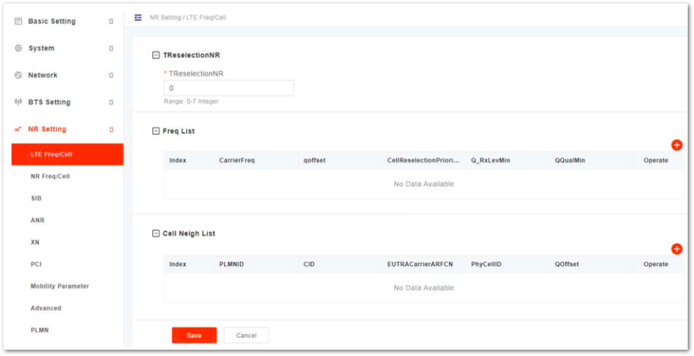 Figure 1: LTE Neighbor Frequency/Cell Settings
Users can add, modify, and delete the LTE neighbor frequency and cell. Up to eight LTE neighbor frequencies and 16 LTE neighbor cells can be set.
- Input TRSelectionNR. (Range from 0 to 7 (integer))
LTE Neighbor Frequency
- In the neighbor frequency list, click
+to enter the page for adding an LTE neighbor frequency. The parameter descriptions are given in Table 17.
Table 17: LTE Neighbor Frequency Parameter Description
| Parameter | Description |
|---|---|
| CarrierFreq | The carrier frequency. Range is from 0 to 3279165 (integer). |
| AllowdMeasBandWidth | The allowable measurement of bandwidth. |
| PresAntenaPort1 | The current antenna port. Value is 0 or 1. |
| Q_OffsetRange | Indicates the difference in signal level between the serving and neighboring gNBs, as determined by the received signal level at the UE. If the received signal level is better from a neighboring gNB by at least this amount of difference in dB, the UE will reselect the other cell. The range is -24 to +24. A typical value is 0 dB. |
| WideBandRsrqMeas | The RSRQ measurement of the bandwidth. Value is 0 or 1. |
| CellReselection Priority | Priority of the cell reselection to cells at this frequency. Range is 0 to 7 (integer). A typical value is 4. |
| ThreshXHigh | The cell reselection threshold for higher priority inter-band frequency. It represents the access threshold level, at which the UE will leave the serving cell and reselect another cell at the target frequency. This occurs if the target frequency cell has a higher reselection priority than the serving cell. Range is 0 to 31 dB. A typical value is 18 dB. |
| ThreshXLow | The cell reselection threshold for lower priority inter-band frequency. It epresents the access threshold level at which the UE will leave the serving cell and reselect another cell at the target frequency. This occurs if the target frequency cell has an absolute priority lower than the serving cell. Range is 0 to 31 dB. A typical value is 13 dB. |
| QRxLevMin | The minimum received signal level at which user equipment (UE) will detect a neighboring gNB’s signal. Range is from -70 to -22. |
| QQualMin | The minimum received signal quality. Range is from -34 to -3. |
| PMaxEUTRA | The maximum transmit power that UEs in this cell are allowed to use in the uplink. Range is -30 to 33 dBm. A typical value is 23 dBm. |
| PLMNID | PLMN ID |
LTE Neighbor Cell
- In the neighbor cell list, click
+to enter the page for adding a LTE neighbor cell, the parameter descriptions are given in Table 18.
Table 18: LTE Neighbor Cell Parameter Description
| Parameter | Description |
|---|---|
| PLMNID | PLMN ID |
| CID | Unique identification number for the Cell. |
| EUTRACarrierARFC | Frequency point of the neighbor cell. |
| PhyCellID | Physical Cell Identifier (PCI) of the neighbor cell. |
| QOffset | Frequency offset this neighbor cell. Indicates the difference in signal level between the serving and this neighboring eNB, as determined by the received signal level at the UE. If the received signal level is better from a neighboring eNB by at least this amount of difference in dB, the UE will reselect this cell. Range is +24 to -24. A typical value is 0 dB. |
| QRxLevMinOffsetCell | Cell minimum received level offset. This parameter represents the cell’s minimum received level offset. It is used only when the UE resides in the VPLMN and cell selection is triggered due to periodic searches for high-priority PLMNS. Range is from 1 to 8. |
| QQualMinOffsetCell | Cell minimum received signal quality offset. This parameter represents the cell’s minimum received signal quality offset. Range is from 1 to 8. |
| CIO | Cell Individual Offset (CIO) is this neighbor gNB’s cell offset, which is one of the variables used to determine which gNB will best serve a given UE. Range is +24 to -24. A typical value is 0 dB. |
| Blacklisted | Blacklisted Value is 0 or 1. |
| TAC | Tracking Area Code (TAC) of this neighbor cell Range is from 0 to 16777215. |
| eNB Type | eNB Type Value is 0 or 1. |
| eNB ID | The global identity of the E-UTRAN cell Range is from 0 to 1048575. |
| No Remove | No remove identity ON or OFF. |
- Click Save to complete the setting of the LTE neighbor frequencies and cells.
NR Neighbor Frequency and Cell Configuration
- In the left navigation column, select NR Setting and then NR Freq/Cell to enter the NR neighbor frequency and cell configuration page, as shown in Figure 30.
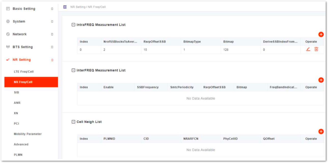 Figure 1: NR Neighbor Frequency/Cell Settings
Users can add, modify, and delete the NR neighbor frequency and cell.
Intra Frequency Measurement
- In the IntraFREQ Measurement list, click
+to enter the page for adding an intra frequency measurement, the parameter descriptions are given in Table 19.
Table 19: Intra Frequency Measurement Parameter Description
| Parameter | Description |
|---|---|
| SSBlocksConsolidationRsrp | The consolidation of Synchronization Signal and PBCH block (SSB) blocks of Reference Signal Receiving Power (RSRP). Range is from 0 to 127. |
| SSBlocksConsolidationRsrq | The consolidation of SSB blocks of Reference Signal Receiving Quality (RSRQ). Range is from 0 to 127. |
| SSBlocksConsolidationSinr | The consolidation of SSB blocks of Signal to Interference plus Noise Ratio (SINR). Range is from 0 to 127. |
| NrofSSBlocksToAverage | This parameter indicates the signal quality of a cell in NR measurement of SSB. Range is from 2 to 16. |
| RsrpOffsetSSB | The SSB offset of RSRP. Range is from 0 to 30. |
| RsrqOffsetSSB | The SSB offset of RSRQ. Range is from 0 to 30. |
| SinrOffsetSSB | The SSB offset of SINR. Range is from 0 to 30. |
| RsrpOffsetCsiRs | The CSI-RS offset of RSRP. Range is from 0 to 30. |
| RsrqOffsetCsiRs | The CSI-RS offset of RSRQ. Range is from 0 to 30. |
| SinrOffsetCsiRs | The CSI-RS offset of SINR. Range is from 0 to 30. |
| BitmapType | Bitmap type Range is 0, 1, 2. |
| Bitmap | Bitmap Range is from 0 to 18446744073709551615. |
| DeriveSSBIndexFromCell | Whether the frame boundaries of all cells at this frequency point are the same. Value is 0 or 1. |
| SSBFrequency | The frequency of SSB. Range is from 0 to 3279165. |
| SubcarrierSpacing | The space between subcarriers. |
| Content Cell | The period of (SSB-based RRM Measurement Timing Configuration) SMTC.
|
| SmtcOffset | The offset of SMTC. Range is from 0 to 159. |
| SmtcDuration | The duration time of SMTC. |
| PLMNID | PLMN ID |
Inter Frequency Measurement
- In the InterFREQ Measurement list, click
+to enter the page for adding an inter frequency measurement, the parameter descriptions are given in Table 20.
Table 20: Inter Frequency Measurement Parameter Description
| Parameter | Description |
|---|---|
| Enable | Enables or disables the inter frequency measurement function.
|
| SSBFrequency | The frequency of SSB. Range is from 0 to 3279165. |
| SubcarrierSpacing | The space between subcarriers. |
| SmtcPeriodicity | The period of (SSB-based RRM Measurement Timing Configuration) SMTC.
|
| SmtcOffset | The offset of SMTC. Range is from 0 to 159. |
| SmtcDuration | The duration time of SMTC. |
| SSBlocksConsolidationRsrp | The consolidation of Synchronization Signal and PBCH block (SSB) blocks of Reference Signal Receiving Power (RSRP). Range is from 0 to 127. |
| SSBlocksConsolidationRsrq | The consolidation of SSB blocks of Reference Signal Receiving Quality (RSRQ). Range is from 0 to 127. |
| SSBlocksConsolidationSinr | The consolidation of SSB blocks of Signal to Interference plus Noise Ratio (SINR). Range is from 0 to 127. |
| NrofSSBlocksToAverage | This parameter indicates the signal quality of a cell in NR measurement of SSB. Range is from 2 to 16. |
| RsrpOffsetSSB | The SSB offset of RSRP. Range is from 0 to 30. |
| RsrqOffsetSSB | The SSB offset of RSRQ. Range is from 0 to 30. |
| SinrOffsetSSB | The SSB offset of SINR. Range is from 0 to 30. |
| RsrpOffsetCsiRs | The CSI-RS offset of RSRP. Range is from 0 to 30. |
| RsrqOffsetCsiRs | The CSI-RS offset of RSRQ. Range is from 0 to 30. |
| SinrOffsetCsiRs | The CSI-RS offset of SINR. Range is from 0 to 30. |
| BitmapType | Bitmap type Values are 0, 1, 2. |
| Bitmap | Bitmap Range is from 0 to 18446744073709551615. |
| DeriveSSBIndexFromCell | Whether the frame boundaries of all cells at this frequency point are the same. Value is 0 or 1. |
| FreqBandIndicatorNR | The indicator of NR frequency bandwidth. Range is from 0 to 1024. |
| Offset To Point A | The offset of Point A. Range is from 0 to 2199. |
| SSB Sub Carrier Offset | The sub carrier offset of SSB. Range is from 0 to 31. |
| PLMNID | PLMN ID |
NR Neighbor Cell
- In the Cell Neigh list, click
+to enter the page for adding a neighbor cell, the parameter descriptions are given in Table 21.
Table 21: Neighbor Cell Parameter Description
| Parameter | Description |
|---|---|
| PLMNID | PLMN ID |
| CID | Unique identification number for the Cell. |
| NRARFCN | Frequency point of the neighbor cell. |
| SSBFrequency | The frequency of SSB. Range is from 0 to 3279165. |
| ReferenceSubcarrierSpacing | The space between reference subcarriers. Range is from 0 to 4. |
| PhyCellID | Physical Cell Identifier (PCI) of the neighbor cell. Range is from 0 to 1007. |
| QOffset | Frequency offset of this neighbor cell. Indicates the difference in signal level between the serving and this neighboring eNB, as determined by the received signal level at the UE. If the received signal level is better from a neighboring eNB by at least this amount of difference in dB, the UE will reselect this cell. Range is +24 to -24. A typical value is 0 dB. |
| QRxLevMinOffsetCell | Cell minimum received level offset. This parameter represents the cell’s minimum received level offset. It is used only when the UE resides in the VPLMN and cell selection is triggered due to periodic searches for high-priority PLMNS. Range is from 1 to 8. |
| QQualMinOffsetCell | Cell minimum received signal quality offset. This parameter represents the cell’s minimum received signal quality offset. Range is from 1 to 8. |
| CIO | Cell Individual Offset (CIO) is this neighbor eNB’s cell offset, which is one of the variables used to determine which eNB will best serve a given UE. Range is +24 to -24. A typical value is 0 dB. |
| Blacklisted | Blacklisted. Value is 0 or 1. |
| TAC | Tracking Area Code (TAC) of this neighbor cell. Range is from 0 to 16777215. |
| No Remove | No remove identity. ON or OFF. |
| gNBIdLength | The length of the gNB ID. |
- Click Save to complete the setting of the NR neighbor frequencies and cells.
SIB Configuration
In the left navigation column, select NR Setting, and then choose SIB to enter the SIB configuration page, as shown in Figure 31.
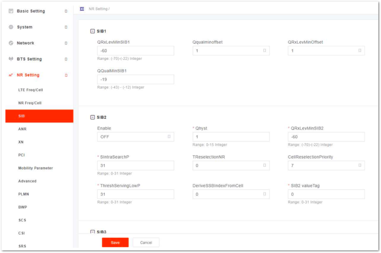 Figure 1: SIB Setting
The gNB supports SIB1 to SIB5. The following tables outline the supported SIB parameters and their corresponding descriptions:
Table 22: SIB1 Parameter Description
| Parameter | Description |
|---|---|
| QRxLevMinSIB1 | The minimum received level of SIB1. Range is from -70 to -22. |
| Qqualminoffset | Cell minimum received signal quality offset. This parameter represents the cell’s minimum received signal quality offset. Range is from 1 to 8. |
| QRxLevMinOffset | Cell minimum received level offset. This parameter represents the cell’s minimum received level offset. It is used only when the UE resides in the VPLMN and cell selection is triggered due to periodic searches for high-priority PLMNS. Range is from 1 to 8. |
| QQualMinSIB1 | The minimum received signal quality of SIB1. Range is from -43 to -12. |
Table 23: SIB2 Parameter Description
| Parameter | Description |
|---|---|
| Enable | Enables or disables SIB2. |
| Qhyst | Delay time for reselection. In general the value of the parameter is 2. Range is from 0 to 15. This parameter will overestimate the signal strength of the serving cell to delay the cell reselection. |
| QRxLevMinSIB2 | The minimum received level of SIB2. Range is from -70 to -22. |
| SIntraSearchP | The threshold of intra frequency measurement. Range is from 0 to 31. |
| TReselectionNR | Cell reselection timer for NR. Range is from 0 to 7. |
| CellReselectionPriority | Priority of the cell reselection to cells at this frequency. Range is 0 to 7 (integer). |
| ThreshServingLowP | The lower priority reselection threshold of serving frequency point. This parameter indicates the threshold when the serving frequency point moves to a lower priority inter-frequency or an Inter-RAT. It applies to the scenario when the UE moves to a lower priority inter-frequency or an Inter-RAT. Range is from 0 to 31. |
| DeriveSSBIndexFromCell | Whether the frame boundaries of all cells at this frequency point are the same. Value is 0 or 1. |
| SIB2 valueTag | The tag of SIB2 value. Range is from 0 to 31. |
Table 24: SIB3 Parameter Description
| Parameter | Description |
|---|---|
| Enable | Enables or disables SIB3 |
| SIB3 valueTag | The tag of SIB3 value. Range is from 0 to 31. |
Table 25: SIB4 Parameter Description
| Parameter | Description |
|---|---|
| Enable | Enables or disables SIB3 |
| SIB3 valueTag | The tag of SIB3 value. Range is from 0 to 31. |
Table 26: SIB5 Parameter Description
| Parameter | Description |
|---|---|
| Enable | Enables or disables SIB3 |
| SIB3 valueTag | The tag of SIB3 value. Range is from 0 to 31. |
ANR Configuration
- In the left navigation column, select NR Setting and then ANR to enter the ANR configuration page, as shown in Figure 32.
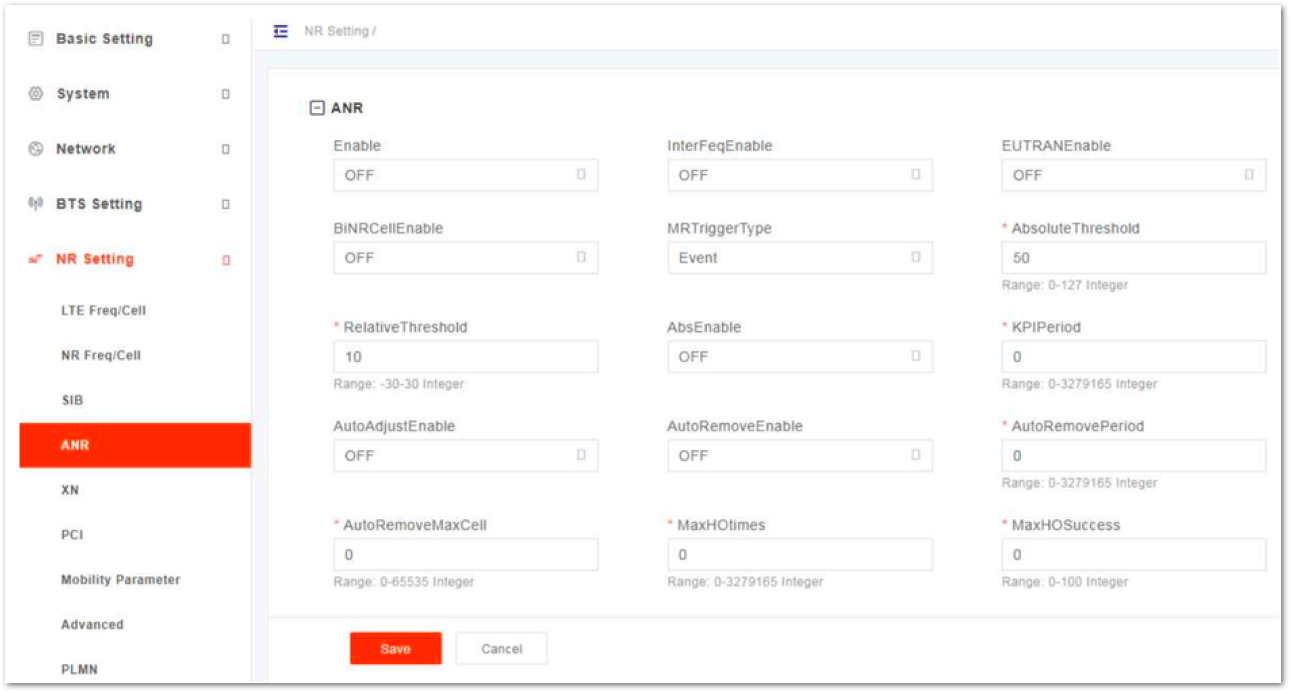 Figure 1: ANR Settings
- Input ANR parameters, the parameter descriptions are shown in Table 27.
Table 27: ANR Parameter Description
| Parameter | Description |
|---|---|
| Enable | Enables or disables the function.
|
| InterFeqEnable | Enables or disables the inter-frequency.
|
| EUTRANEnable | Enables or disables the EUTRAN.
|
| BiNRCellEnable | Enables or disables the BiNR cell.
|
| MRTriggerType | MR trigger type
|
| AbsoluteThreshold | Absolute threshold Range is from 0 to 127. |
| RelativeThreshold | Relative threshold Range is from -30 to 30. |
| AbsEnable | Enables or disables the Abs.
|
| KPIPeriod | The period of KPI. Range is from 0 to 3279165. |
| AutoAdjustEnable | Enables or disables the auto adaptive.
|
| AutoRemoveEnable | Enables or disables the auto remove.
|
| AutoRemovePeriod | The period of auto remove. Range is from 0 to 3279165. |
| AutoRemoveMaxCell | The maximum cells of auto remove. Range is from 0 to 65535 |
| MaxHOtimes | The maximum handover time. Range is from 0 to 3279165. |
| MaxHOSuccess | The maximum successful handover time. Range is from 0 to 100. |
- Click Save to complete the ANR setting.
- Input XN parameters, the parameter descriptions are shown in Table 28.
Table 28: XN Parameter Description
| Parameter | Description |
|---|---|
| PLMNID | PLMN ID |
| RemoteAddress | The remote IP address. |
| XnLinkEnable | Enables or disables the XN link.
|
| XnHoEnable | Enables or disables the XN handover.
|
| BlackList IP | IP addresses of the blacklist. |
XN Configuration
- In the left navigation column, select NR Setting and then XN to enter the XN configuration page, as shown in Figure 33.
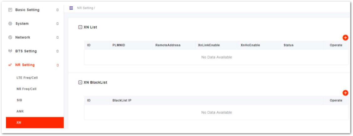 Figure 1: XN Settings
- In the XN list, click
+to pop up the XN configuration parameters. - Click OK to complete the XN setting.
- In the XN black list, click
+to pop up the black configuration parameter. - Input the IP addresses of the blacklist.
- Click Save to complete the blacklist setting.
PCI Configuration
- In the left navigation column, select NR Setting and then PCI to enter the PCI configuration page, as shown in Figure 34.
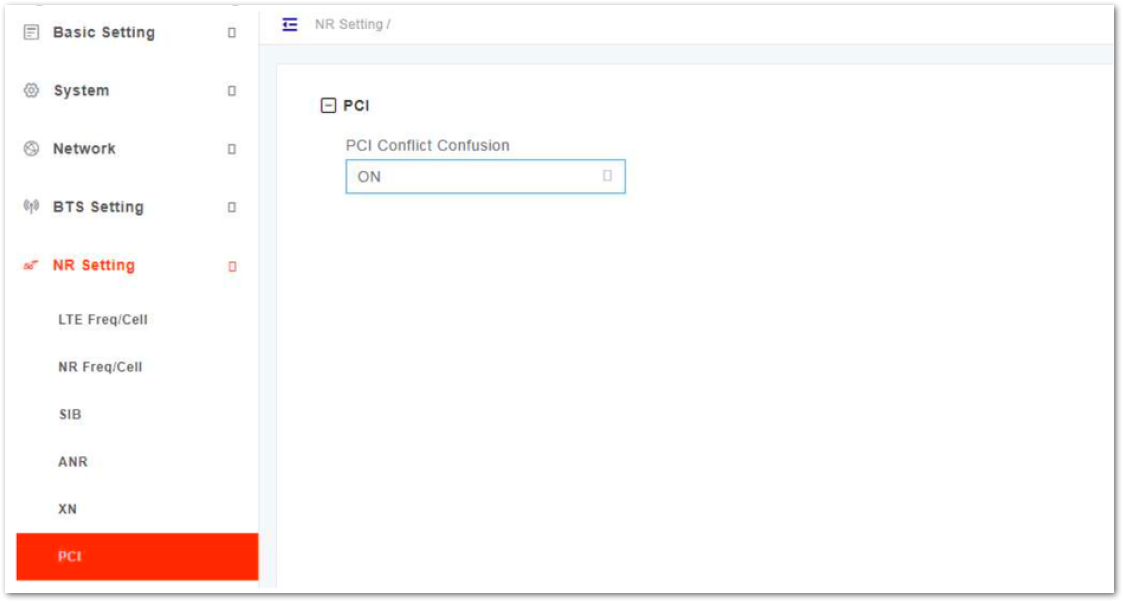 Figure 1: PCI Setting
- Select whether enable the PCI conflict detection function.
- Click Save to complete the PCI setting.
Mobility Parameter Configuration
In the left navigation column, select NR Setting and then Mobility Parameter to enter the mobility parameter configuration page. The Mobility Parameter menu pertains to how roaming UE sessions are handled between different gNBs in the same service area. When a UE is actively connected to a gNB it is referred to as the serving gNB or cell. The other gNBs in the area are referred to as either neighbor or target gNBs or cells.
The process of a device moving from cell to cell and changing over from its serving gNB to a neighbor (target) gNB is called handoff or handover. The UE exchanges information with its serving gNB to perform cell selection and reselection based on parameters which you will set for each gNB.
Event Threshold
The A1 event is triggered when the serving cell’s Reference Signal Received Power (RSRP) is better than the A1 threshold. The A1 event can be used to turn off certain inter-cell measurements. The conditions for entering A1 event are shown in Formula 1, and the conditions for leaving A1 event are shown in Formula 2.
Formula 1:
(Ms - Hys) < Thresh
Formula 2:
(Ms + Hys) < Thresh
Ms indicates the measurement results of the serving cell with no offset. Hys indicates the hysteresis parameter of the event. Thresh indicates the preset threshold.
- In the A1 list, click
+to display A1 event configuration parameters, which are shown in Table 29.
Table 29: A1 Event Threshold Parameter Description
| Parameter | Description |
|---|---|
| A1 | Enables or disables the A1 event.
|
| Threshold Trigger Type | The trigger type of the A1 threshold, including RSRP, RSRQ, and SINR. |
| A1 Threshold RSRP | The RSRP threshold value for triggering A1 event. Range is from 0 to 127. |
| A1 Threshold RSRQ | The RSRQ threshold value for triggering A1 event. Range is from 0 to 127. |
| A1 Threshold SINR | The SINR threshold value for triggering A1 event. Range is from 0 to 127. |
| Report On leave | Indicator of A1 event on leave.
It indicates whether the UE initializes the measurement reporting process when cells in the Triggered List are in leaving state.
|
| Hysteresis | This parameter refers to the hysteresis (historical records) of the handover measurement event. The value is used to avoid the frequent triggering of cell handover evaluation due to the fluctuation in wireless signals. This setting tells the UE, if you hear another gNB with at least this amount of dB better, initiate a handover. The lower the number the sooner the handover is initiated. If set too low, it may cause the UE to ping-pong between gNBs. Range is from 0 to 30 dB. |
| Max Report Cells | The maximum cells of reported. Range is from 0 to 8. |
| Measure Purpose | Indicates the usage of configuring the A1 event. Range is from 0 to 100.
|
| Report Amount | The number of report. Range is from 1 to 100. |
| MaxNrofRSIndexToReport | The maximum number of RS measurement reports. Range is from 1 to 32. |
| Report Interval | The report interval of A1 event triggering report. |
| Report Quantity | The quantity of the measurement report. |
| Report Quantity RS IDX | The RS measurement report of the A1 event, including RSRP, RSRQ, and SINR. |
| Time To Trigger | Trigger time |
| RS Type | RS type, including SSB and CSI-RS. |
| Include Beam Measurements | Enables or disables the beam measurement indicator.
|
| PLMN | PLMN ID |
- Click Save to complete the A1 event threshold setting.
A2 Event Threshold
The A2 event is triggered when the serving cell’s Reference Signal Received Power (RSRP) is better than the A2 threshold.
- In the A2 list, click
+to display A2 event configuration parameters. - Input the value of A2 event, which is the same as A1 event, refer to Table 29.
- Click Save to complete the A2 event threshold setting.
A3 Event Threshold
The A3 event is triggered when the neighbor cell becomes better than the serving cell by as much as the offset value. The offset can be either positive or negative.
- In the A3 list, click
+to display A3 event configuration parameters. - Input the value of A3 event, which is the same as A1 event, refer to Table 29.
- Click Save to complete the A3 event threshold setting.
A4 Event Threshold
The A4 event is triggered when the neighbor cell becomes better than the serving cell by as much as the relative threshold value. A4 event is used to the handover based on coverage of intra-frequency and inter-frequency.
- In the A4 list, click
+to display A4 event configuration parameters. - Input the value of A4 event, which is the same as A1 event, refer to Table 29.
- Click Save to complete the A4 event threshold setting.
A5 Event Threshold
The A5 event is triggered when the serving cell becomes worse than Threshold 1 while a neighbor cell becomes better than Threshold 2. A5 event can control the edge of handover out of the serving cell and the edge of handover in of the neighbor cell.
- In the A5 list, click
+to display A5 event configuration parameters. - Input the value of A5 event, which is the same as A1 event, refer to Table 29.
- Click Save to complete the A4 event threshold setting.
B1 Event Threshold
The B1 Event Thresholds pertains the neighbor is better than the absolute threshold, which is used to measure the RAT cell with high priority.
- In the B1 list, click
+to display B1 event configuration parameters, which are shown in Table 30.
Table 30: B1 Event Threshold Parameter Description
| Parameter | Description |
|---|---|
| B1 | Enables or disables the B1 event.
|
| Threshold Trigger Type | The trigger type of the B1 threshold, including RSRP, RSRQ, and SINR. |
| B1 Threshold1 EUTRA RSRP | The RSRP threshold value for triggering B1 event. Range is from 0 to 127. |
| B1 Threshold1 EUTRA RSRQ | The RSRQ threshold value for triggering B1 event. RSRQ Range is from 0 to 127. |
| B1 Threshold1 EUTRA SINR | The SINR threshold value for triggering B1 event. Range is from 0 to 127. |
| Hysteresis | This parameter refers to the hysteresis (historical records) of the handover measurement event. The value is used to avoid the frequent triggering of cell handover evaluation due to the fluctuation in wireless signals. This setting tells the UE, if you hear another gNB with at least this amount of dB better, initiate a handover. The lower the number the sooner the handover is initiated. If set too low, it may cause the UE to ping-pong between gNBs. Range is from 0 to 30 dB. |
| Max Report Cells | The maximum cells of reported. Range is from 0 to 8. |
| Measure Purpose | Indicates the usage of configuring the B1 event. Range is from 0 to 100.
|
| Report Amount | The number of report. Range is from 1 to 100. |
| Report Interval | The report interval of B1 event triggering report |
| Time To Trigger | Length of time the target cell RSRP value is better than the serving cell before the UE initiates a handover request. |
| Report Quantity | The RS measurement report of the B1 event, including RSRP, RSRQ, and SINR. |
| Report On leave | Enables or disables the beam measurement indicator.
|
| PLMN | PLMN ID |
- Click Save to complete the B1 event threshold setting.
B2 Event Threshold
The B2 Event Thresholds pertains only to TD-SCDMA and GSM adjacent cells, not to adjacent LTE cells.
- In the B2 list, click
+to display B2 event configuration parameters. - Input the value of B2 event, which is the same as B1 event, refer to Table 30.
- Click Save to complete the B2 event threshold setting.
Period Measurement Parameter
- In the Period Measure list, click
+to display period measurement configuration parameters, which are shown in Table 31.
Table 31: Period Measurement Parameter Description
| Parameter | Description |
|---|---|
| Report Quantity | The RS measurement report of the B1 event, including RSRP, RSRQ, and SINR. |
| Max Report Cells | The maximum cells of reported. Range is from 0 to 8. |
| Report Interval | The report interval of A1 event triggering report |
| Report Amount | The number of report. Range is from 1 to 100. |
- Click Save to complete the period measurement setting
Advanced Parameter Configuration
On the left navigation column, select NR Setting and then Advanced to enter the advanced parameter configuration page.
CU
- Click
+in the front of CU to display CU configuration parameters, as shown in Table 32.
Table 32: CU Parameter Description
| Parameter | Description |
|---|---|
| NR T300 | RRC timer. When the gNB receives the RRCSetupRequest message, the timer starts up. |
| NR T301 | RRC timer. When the gNB receives the RRCReestabilshmentRequest message, the timer starts up. |
| NR T304 | RRC timer. When the gNB receives the RRC reconfiguration message with synchronization, the timer starts up. |
| NR T310 | RRC timer. When the gNB receives the continuous “out-of-sync” message from the bottom layer, the timer starts up. |
| NR T311 | RRC timer. When the RRC reestablishment is triggered, the timer starts up. |
| NR N310 | This parameter is used to indicate that the Pcell receives the maximum continuous “out-of-sync” message from the bottom layer. |
| NR N311 | This parameter is used to indicate that the Pcell receives the maximum continuous “in-sync” message from the bottom layer. |
| NR T319 | RRC timer. When the gNB receives the RRCResumeRequest message, the timer starts up. |
| F1ap Local IP | The CU IP address in control plane of F1 interface. |
| F1U IP | The CU IP address in user plane of F1 interface. |
| NGAP Local IP | The local CU IP address of the NG interface. Click + to all multiple IP addresses. |
| NGU IP | The IP address of the NGU. Click + to all multiple IP addresses. |
| AMF IP | The peer AMF IP address of the NG interface. Click + to all multiple IP addresses. |
- Click Save to complete the CU setting.
DU
- Click
+in the front of DU to display DU configuration parameters, as shown in Table 33.
Table 33: DU Parameter Description
| Parameter | Description |
|---|---|
| Offset To Point A | The offset to point A. The unit is RB. Range is from 0 to 2199. |
| SSB Sub Carrier Offset | The offset of SSB sub carrier. Range is from 0 to 31. |
| ReferenceSubcarrierSpacing | The space of reference sub carrier. Range is from 0 to 4. |
| PAT1 DL UL Trans Periodicity | Subframe ratio. The Uplink and downlink transmission period of PAT1. Range is from 0 to 7. |
| PAT1 of Downlink Slots | Subframe ratio. The downlink time slot configuration of PAT1. Range is from 0 to 320. |
| PAT1 of Downlink Symbols | Subframe ratio. The special time slot downlink symbol configuration of PAT1. Range is from 0 to 13. |
| PAT1 of Uplink Slots | Subframe ratio. The uplink time slot configuration of PAT1. Range is from 0 to 320. |
| PAT1 of Uplink Symbols | Subframe ratio. The special time slot uplink symbol configuration of PAT1. Range is from 0 to 13. |
| PAT2 DL UL Trans Periodicity | Subframe ratio. The Uplink and downlink transmission period of PAT2. Range is from 0 to 7. |
| PAT2 of Downlink Slots | Subframe ratio. The downlink time slot configuration of PAT2. Range is from 0 to 320. |
| PAT2 of Downlink Symbols | Subframe ratio. The special time slot downlink symbol configuration of PAT2. Range is from 0 to 13. |
| PAT2 of Uplink Slots | Subframe ratio. The uplink time slot configuration of PAT1. Range is from 0 to 320. |
| PAT2 of Uplink Symbols | Subframe ratio. The special time slot uplink symbol configuration of PAT1. Range is from 0 to 13. |
| Max DL HARQ ReTX | The maximum number of downlink HARQ retransmission. Range is from 0 to 4. |
| DL LA | Downlink AMC auto adaptive switch.
|
| Max UL HARQ ReTX | The maximum number of uplink HARQ retransmission. Range is from 0 to 4. |
| UL LA | Uplink AMC auto adaptive switch
|
| CsiRsReporting | CSI report switch.
|
| DU F1AP Local IP | The DU IP address in control plane of F1 interface. |
| DU F1U IP | The DU IP address in user plane of F1 interface. |
| DU F1AP Remote IP | The Remote IP address in control plane of F1 interface. |
| numForceGrant | (Reserved) |
| HealthTimeInterval | (Reserved) |
| PerfOptFlag | (Reserved) |
| CalcPaddingRateFlag | Calculate Padding rate flag |
- Click Save to complete the DU setting.
SSB
- Click
+in the front of SSB to display SSB configuration parameters, as shown in Table 34.
Table 34: PCI Range Parameter Description
| Parameter | Description |
|---|---|
| SSB Periodicity | The period of SSB. The unit is ms. Range is from 0 to 5 |
| SSB Power | The transmission power of SSB. Range is from -60 to 50. |
| SSB Absolute Freq | The frequency point of SSB. Range is from 0 to 3279165. |
| SsbResourceReserved | The reserved resource of SSB.
|
- Click Save to complete the SSB setting.
UL RSSI Measurement
In this software version, UL RSSI is not supported.
DRX
- Click
+in the front of DRX to display Discontinuous reception (DRX) configuration parameters, as shown in Table 35.
Table 35: DRX Parameter Description
| Parameter | Description |
|---|---|
| DRXOnDurationTimer | The duration timer of DRX. |
| DRXInactivityTimer | The inactivity timer of DRX. |
| DRXHarqRttTimerDL | The number of symbols received in the downlink BWP transfer block. The retransmission of the downlink process will be scheduled after this timer ending. The scheduling window is within drX-RetransmissionTimerdl. Range is from 0 to 56. |
| DRXHarqRttTimerUL | The number of symbols received in the uplink BWP transfer block. The retransmission of the uplink process will be scheduled after this timer ending. The scheduling window is within drX-RetransmissionTimerUL. When the last symbol of PUSCH is sent, the drx-HARQ-RTT-TimerUL starts up. Range is from 0 to 56. |
| DRXRetransmissionTimerDL | The downlink retransmission timer of DRX. |
| DRXRetransmissionTimerUL | The uplink retransmission timer of DRX. |
| LongDRXCycle | Long DRX period |
| DRXStartOffset | Specify the start sub frame of the DRX period. Range is from 0 to 10239. |
| ShortDRXCycle | Short DRX period |
| ShortCycleTimer | The timer of DRX short period. Range is from 0 to 16.
|
| DRXSlotOffset | DRX Slot offset Range is from 0 to 31. |
- Click Save to complete the DRX setting.
Voice
- Click
+in the front of Voice to display the voice configuration parameters, as shown in Table 36.
Table 36: Voice Parameter Description
| Parameter | Description |
|---|---|
| VONR | Voice Over NR
|
| EPS Fallback Type | EPS fallback type, including five types.
|
- Click Save to complete the voice setting.
GNB
- Click
+in the front of GNB to display the gNB configuration parameters, as shown in Table 37.
Table 37: GNB Parameter Description
| Parameter | Description |
|---|---|
| GNB ID Length | The length of GNB ID. Range is from 22 to 32. |
| GNB ID | GNB ID Range is from 0 to 4294967295. |
| GNB Name | GNB name Range is from 0 to 150 bytes. |
- Click Save to complete the gNB setting.
Multi PLMN
- Click
+in the front of Multi PLMN to display multi PLMN configuration parameters. - Whether enable multi PLMN.
- Click Save to complete the multi PLMN setting.
PLMN Configuration
- In the left navigation column, select NR Setting and then PLMN to enter the PLMN configuration page, as shown in Figure 35.
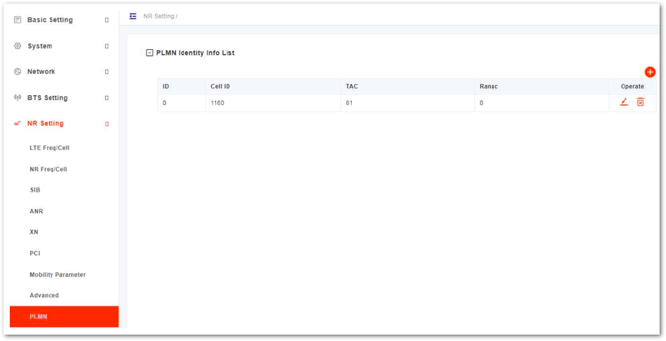 Figure 1: PLMN Settings
- Click
+to display PLMN configuration parameters, as shown in Table 38.
Table 38: PLMN Parameter Description
| Parameter | Description |
|---|---|
| Cell ID | Cell ID Range is from 0 to 68719476735. |
| TAC | TAC Range is from 0 to 16777215. |
| Ranac | Ranac |
- Click Save to complete the PLMN setting.
BWP Configuration
In this software version, BWP is not supported.
SCS Configuration
- In the left navigation column, select NR Setting and then SCS to enter the Sub-carrier Space (SCS) configuration page, as shown in Figure 36.
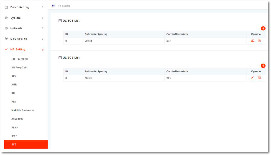 Figure 1: SCS Setting
- In the DL SCS list, click
+to display the downlink SCS parameters, whose descriptions are shown in Table 39.
Table 39: DL SCS Parameter Description
| Parameter | Description |
|---|---|
| SubcarrierSpacing | The sub carrier spacing is 30 kHz. |
| CarrierBandwidth | The bandwidth of the carrier. Values are 25, 52, 79, 106, 133, 160, 216, 273. |
The configuration of UL SCS is the same as DL SCS configuration.
- Click Save to complete the uplink/downlink SCS setting.
CSI Configuration
- In the left navigation column, select NR Setting and then CSI to enter the CSI configuration page, as shown in Figure 37.
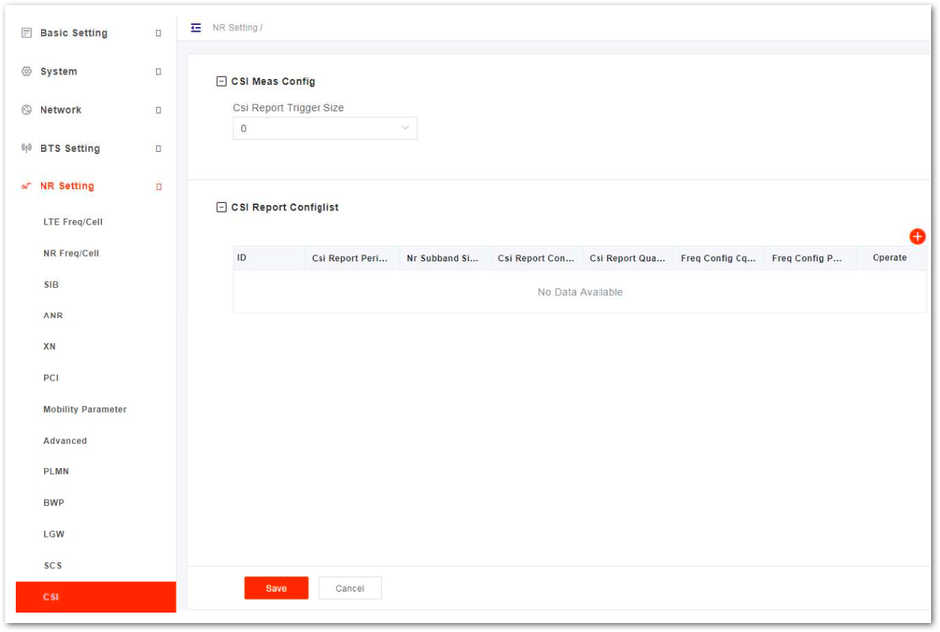 Figure 1: CSI Setting
- Click
+to display CSI configuration parameters, the configuration parameter description is shown in Table 40.
Table 40: CSI Parameter Description
| Parameter | Description |
|---|---|
| Parameter | Description |
| Csi Report Periodicity | CSI report period |
| Nr Subband Size | NR sub-band size |
| Csi Report Config Type | The configuration type of the CSI report.
|
| Csi Report Quantity | CSI report quantity |
| Freq Config Cqi Format Ind | CQI format
|
| Freq Config Pmi Format Ind | PMI format
|
- Click Save to complete the CSI setting.
SRS Configuration
In this software version, SRS is not supported.
PUSCH Configuration
- In the left navigation column, select NR Setting and then PUSCH to enter the PUSCH page, as shown in Figure 38.
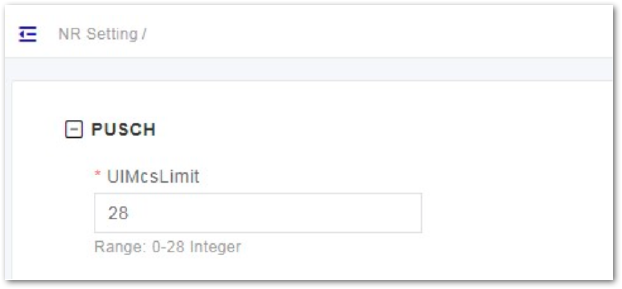 Figure 1: PUSCH Setting
- Input the value of UlMcsLimit. Range is from 0 to 28.
- Click Save to complete the PUSCH setting.
PDSCH Configuration
- In the left navigation column, select NR Setting and then PDSCH to enter the PDSCH page, as shown in Figure 39.
 Figure 1: PDSCH Setting
- Input PDSCH configuration parameters, whose descriptions are shown in Table 41.
Table 41: PDSCH Parameter Description
| Parameter | Description |
|---|---|
| Power Control | Enables or disables the power control function.
|
| Power Control Value Start | The start value of power control. Range is from -6 to 6. |
| Power Control Value End | The end value of power control. Range is from -6 to 6. |
| DIMcsLimit | The limit of uplink MCS. Range is from 0 to 28. |
- Click Save to complete the PDSCH setting.
PUCCH Configuration
- In the left navigation column, select NR Setting and then PUCCH to enter the PUCCH page, as shown in Figure 40.
 Figure 1: PUCCH Setting
- Input PUCCH configuration parameters, which description is shown in Table 42.
Table 42: PUCCH Parameter Description
| Parameter | Description |
|---|---|
| ClpcPucchEnable | Enables or disables Clpc PUCCH.
|
| ClpcPucchSinrEnable | Enables or disables Clpc PUCCH SINR.
|
| ClpcPucchBlerEnable | Enables or disables Clpc PUCCH BLER.
|
- Click Save to complete the PUCCH setting.
QoS Configuration
- In the left navigation column, select NR Setting and then QoS to enter the QoS configuration page, as shown in Figure 41.
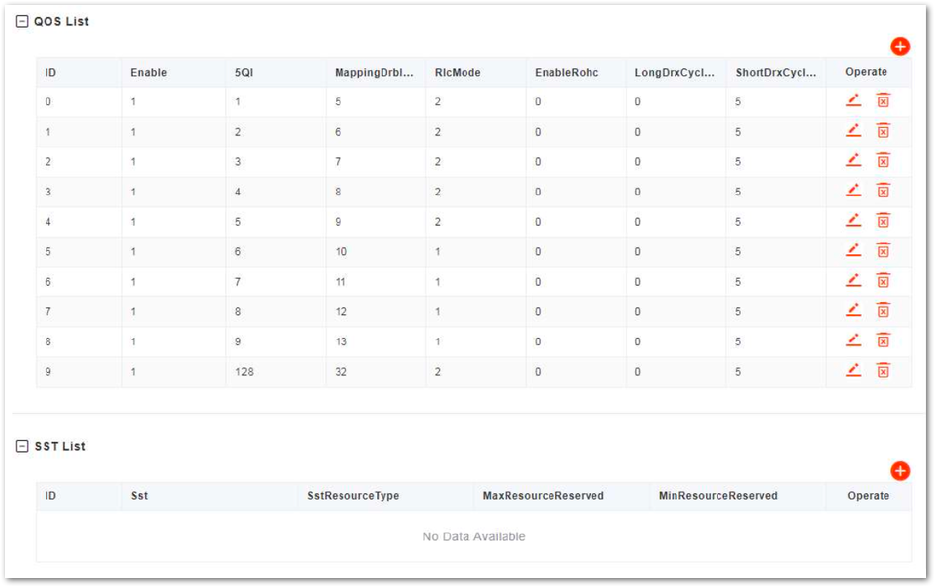 Figure 1: QoS Setting
- In the QoS list, click
+to display the QoS configuration parameters, whose descriptions are shown in Table 43.
Table 43: QoS Parameter Description
| Parameter | Description |
|---|---|
| Enable | Enables or disables QoS function. |
| MappingDrbIndex | Index |
| 5QI | 5QI Range is from 1 to 255. |
| Type | GBR Non-GBR |
| Priority | Priority Range is from 1 to 16. |
| MinBr | MinBr |
| IsDefault | Whether the QoS is default. |
| UeInactivityTimerConifg | UE inactivity Timer |
| TReorderingPdcp | TReordering PDCP Range is from 0 to 35. |
| TReorderingUE | TReordering UE Range is from 0 to 35. |
| DiscardTimer | Discard timer |
| StatusReportRequired | Enables or disables report status. |
| PdcpSnSizeUl | Uplink PDCP SN size |
| PdcpSnSizeDl | Downlink PDCP SN size |
| Dscp | DSCP |
| RlcMode | RLC mode.UMAM |
| SnFieldLengthAmDl | Range is from 0 to 35. |
| SnFieldLengthAmUl | Range is from 0 to 35. |
| SnFieldLengthUmDl | Range is from 0 to 35. |
| SnFieldLengthUmUl | Range is from 0 to 35. |
| UlConfig | Uplink configuration Values are 0, 1, 2. |
| EnableRohc | Enables or disables ROHC. |
| RohcProfile0x0001 | ROHC profile |
| RohcProfile0x0002 | ROHC profile |
| RohcProfile0x0006 | ROHC profile |
| PdcpDuplicationActivated | |
| PrimaryPathDl | Downlink primary path |
| PrimaryPath | Whether the path is primary |
| UlDataSplitThreshold | Uplink data split threshold |
| DlDataSplitThreshold | Downlink data split threshold |
| AllowedIntegrityAlgo | Allowed integrity algorithm |
| LongDrxCycle | Long DRX cycle |
| ShortDrxCycle | Short DRX cycle |
| ShortDRXcycle | Short DRX cycle timer |
| DrbInactivityTimerConfig | DRB inactivity timer |
- In the SST list, click to display the SST configuration parameters, whose descriptions are shown in Table 44.
Table 44: SST Parameter Description
| Parameter | Description |
|---|---|
| SST | Enables or disables SST. |
| SstResourceType | SST source type |
| MaxResourceReserved | The maximum reserved resource. Range is from 0 to 273. |
| MinResourceReserved | The minimum reserved resource. Range is from 0 to 273. |
- Click Save to complete the QoS setting.
TestMAC Configuration
In this software version, testMAC is not supported.
