WisGateOS 2 2.2.x or Later
If your gateway firmware is WisGateOS 2 2.2.x or later. Installing extensions becomes easier, you can select and install extensions from the Extension gallery.
How to Add an Extension
You can install extensions in two ways:
Install from Extension Gallery
- To install an extension, access the gateway by referring to the Access the Gateway section, using the RAK7240V2 WisGate Edge Prime documentation as a reference example.
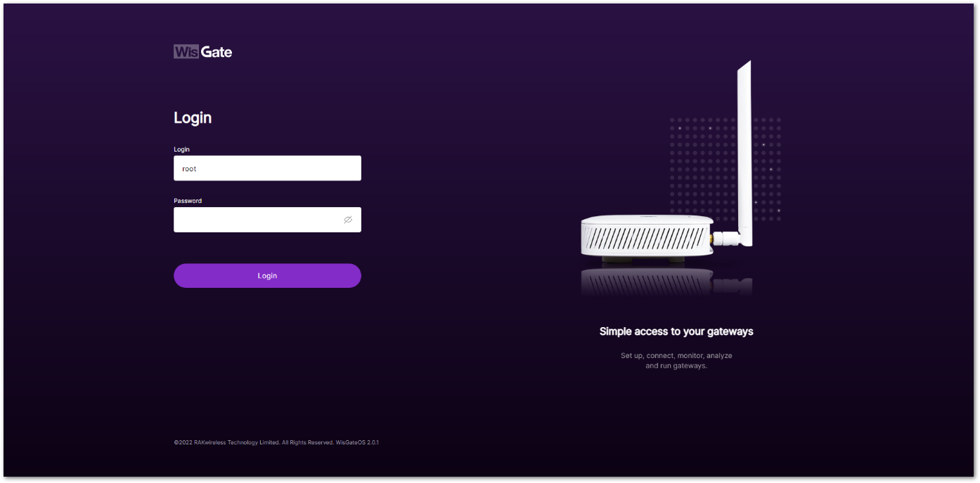 Figure 1: Login page
- Once logged in successfully, navigate to the Extensions tab (
 ).
).
- You can click on the WisGate logo (
 ) to expand the menu on the left and see the full names of the tabs.
 - By default, no extensions are installed.
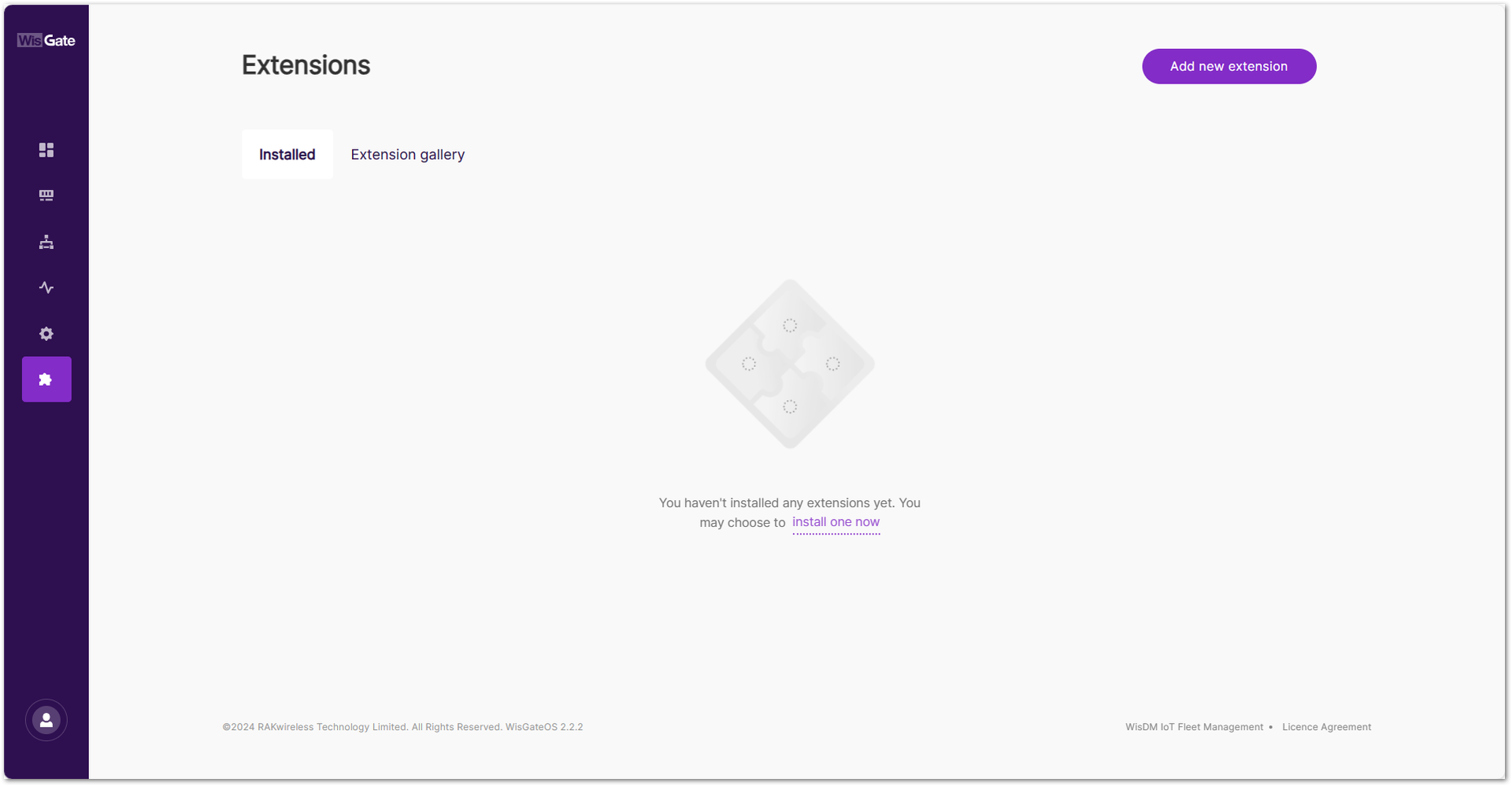 Figure 1: Extensions tab
- Proceed with the installation by clicking on the Extension gallery tab. All extensions that support WisGateOS 2 2.2.x or later will be displayed in the gallery.
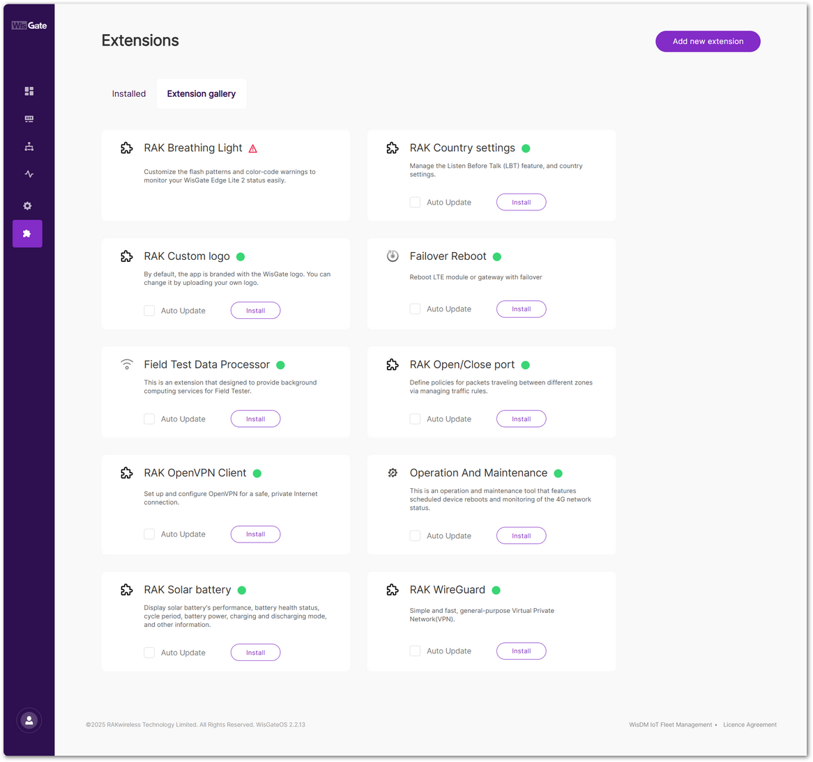 Figure 1: Extension gallery
- Select the desired extension, such as RAK OpenVPN Client, and click the Install button. The process may take a few moments to complete.
- If the icon
 appears on the Extension tab, it means that the gateway hardware does not support the installation of this extension.
 - If the icon 🟢 appears on the Extension tab, it means that the gateway hardware support the installation of this extension. You can choose to install this extension.
- If the Auto Update is enabled during installation, the gateway will automatically update the extension when the latest version is available.
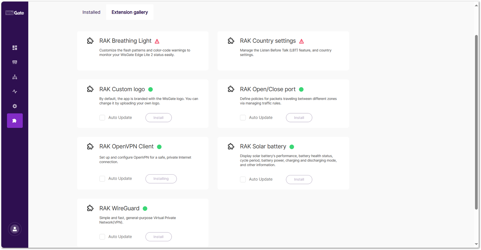 Figure 1: Installing extension
- Once installed, go to the Installed tab where the newly installed extension should now be visible.
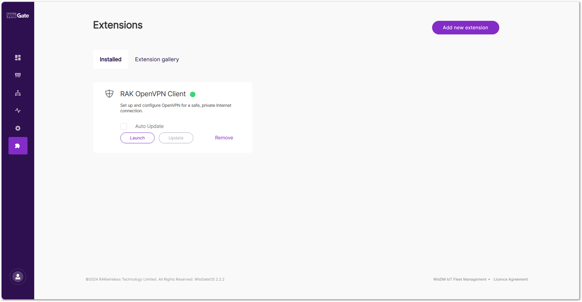 Figure 1: Installed extension
Manually Upload an Extension
In addition to the Extension Gallery, users can manually upload a custom extension package in .ipk format.
- In the Extensions tab, click Add new extension.
- Drag and drop your
.ipkfile into the upload area, or click choose file to select it manually.
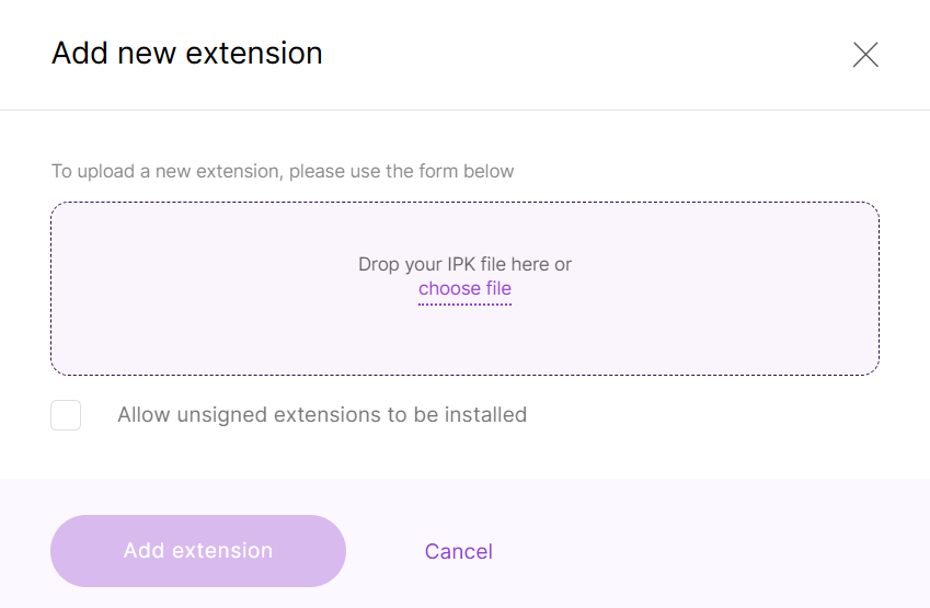 Figure 1: Add an extension file
- Check Allow unsigned extensions to be installed if you want to install an unsigned package.
- Click Add extension to complete the installation.
How to Remove an Extension
- Navigate to the Extensions > Installed and click on the Remove button of the extension you want to uninstall.
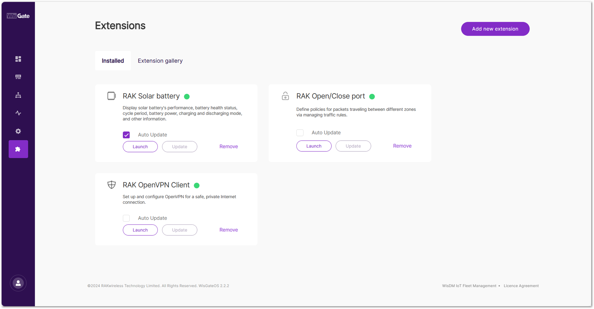 Figure 1: Installed Extension
- A pop-up window will appear to verify if you want delete the extension. Click Remove and wait for the process to finish.
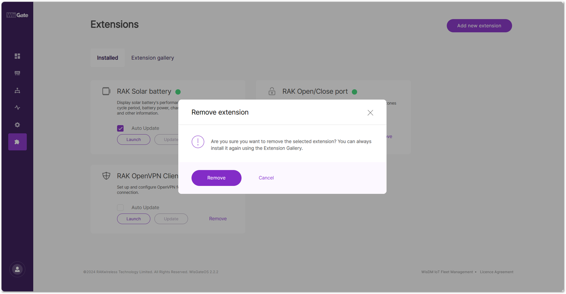 Figure 1: Removing an Extension
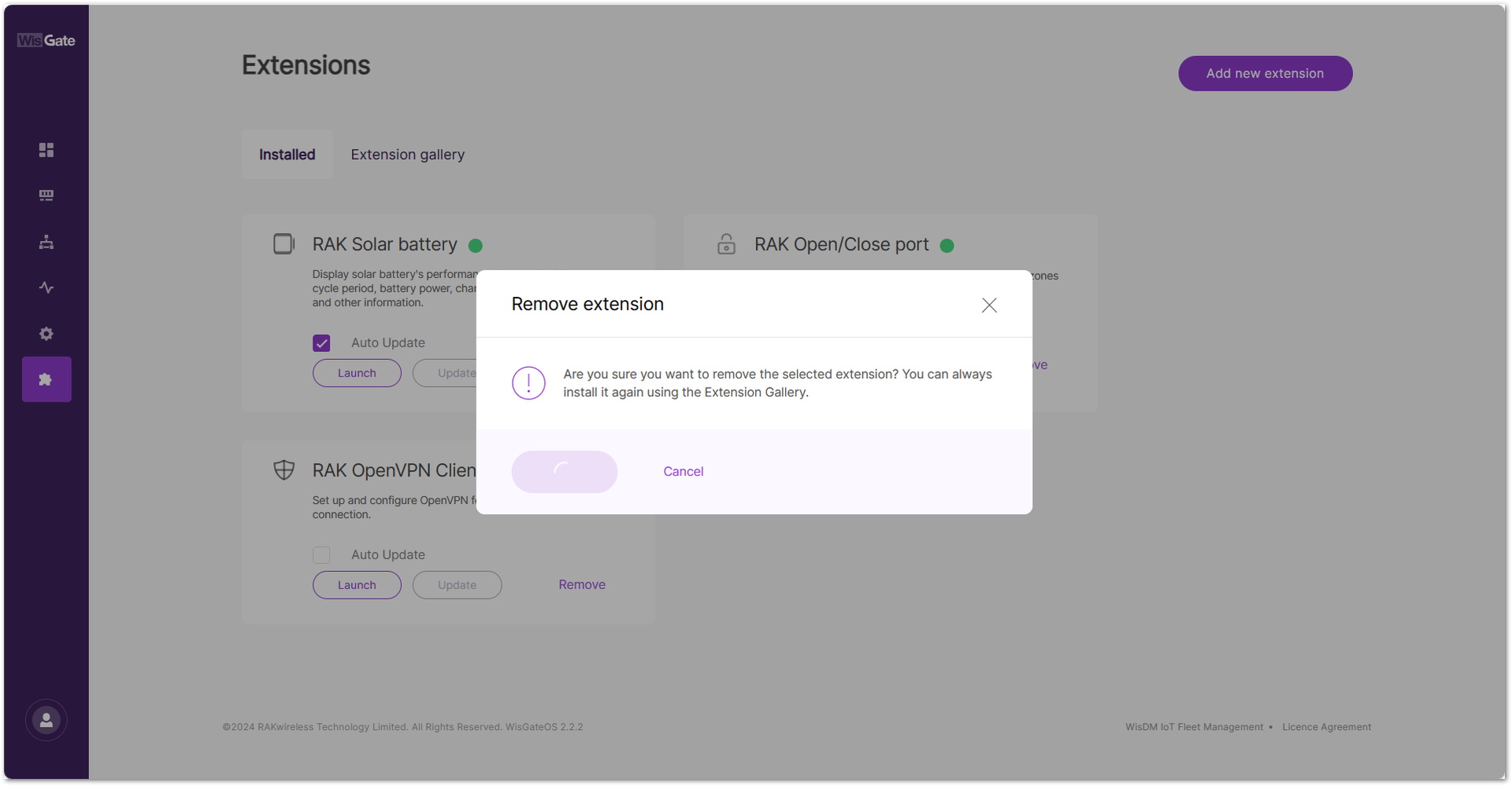 Figure 1: Removing extension
At this point, the uninstalled extension will no longer appear on the Extensions page.
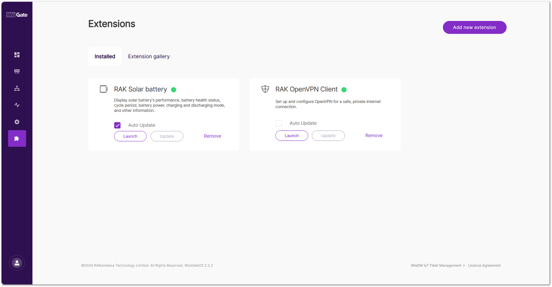 Figure 1: Extension is removed
How to Update an Extension
In order to use the latest features of the extension, it is strongly recommend to update the extension to its latest version.
- To update an extension, navigate to the Extensions > Installed.
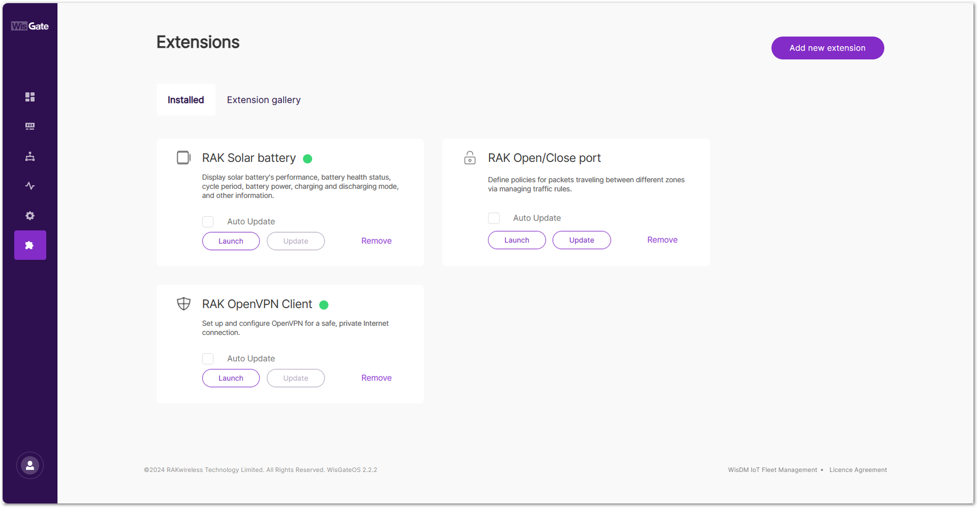 Figure 1: Installed extensions page
- If the latest version of the extension is available, the Update button will be highlighted, indicating that you can choose to update the extension. For example, the RAK Open/Close port extension. Click Update. The process may take a few moments to complete.
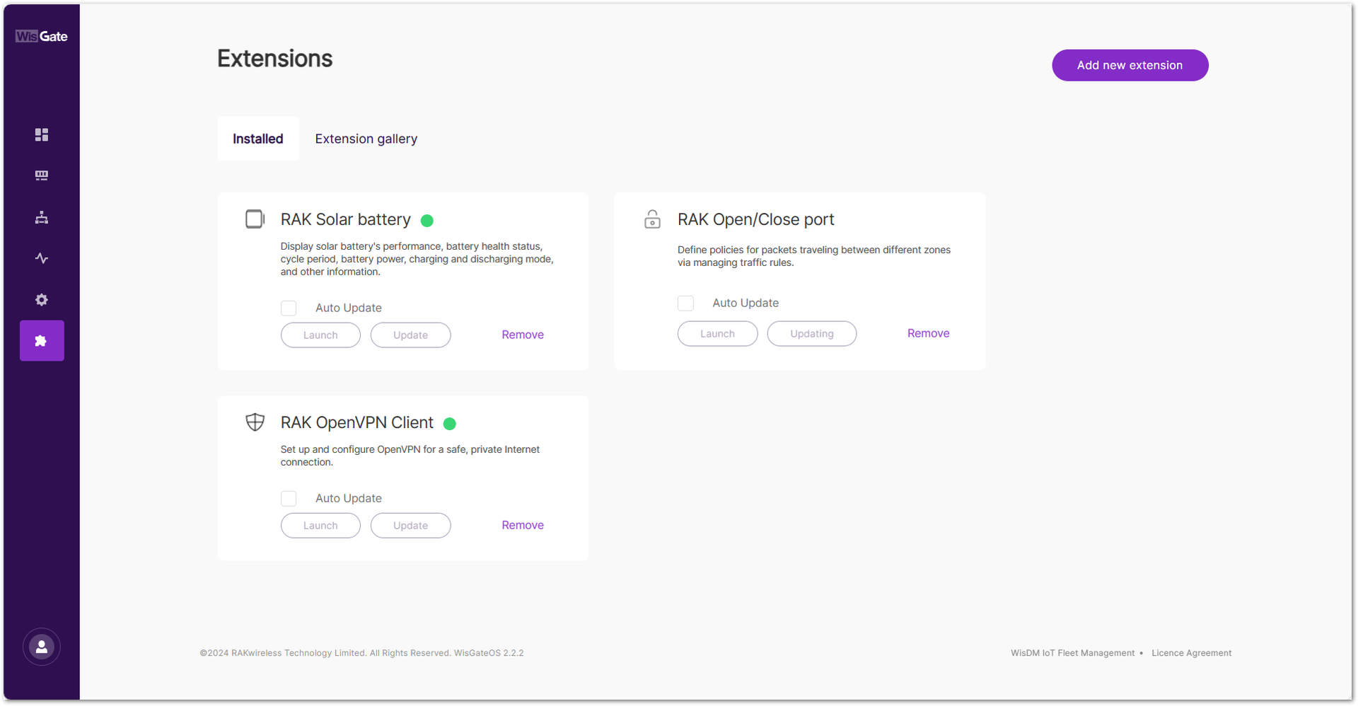 Figure 1: Updating extension
After the update is complete, the extension will show as up to date, with no further updates available.
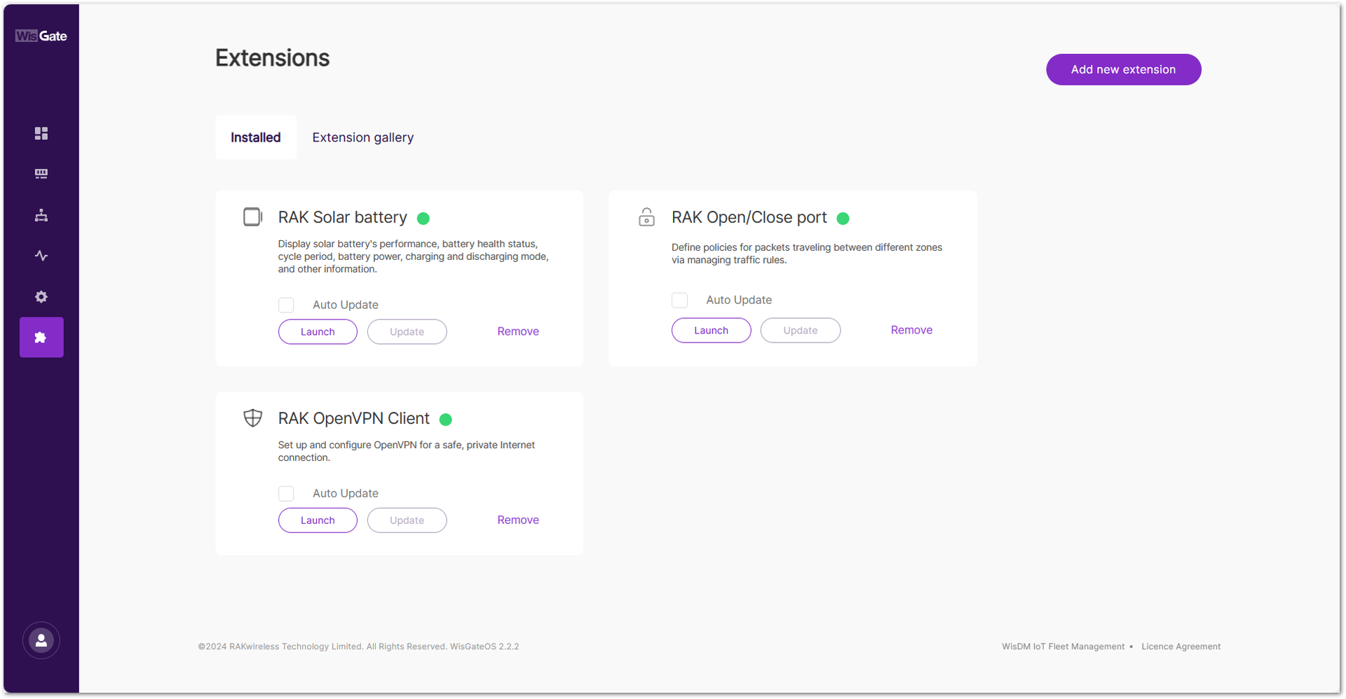 Figure 1: Updated extension
To facilitate timely updates, the RAK gateway provides an automatic update feature. It allows you to check the Auto Update button on the extension tab. Once Auto Update is enabled, the gateway will automatically update the extension when the latest version is available.
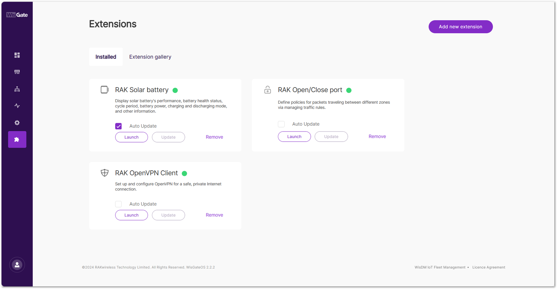 Figure 1: Auto Update
How to Use the Extensions
RAK Breathing Light
The breathing light LED is located on the top cover of the WisGate Edge Lite 2 gateways, making it easy to visually identify the gateway's status. This extension allows you to enable or disable the breathing light, which operates by default with a slowly blinking blue light.
The Breathing Light extension is available for the WisGate Edge Lite 2 and WisGate Soho Lite gateways.
Working Mode
By using the Breathing Light extension, the working mode, frequency, and color of the LED light are now customizable. This extension has two working modes: All and Warning Only.
- Choosing the All mode can:
- Change the Normal light color, that is the light you see when the gateway is working properly.
- Set the blinking frequency from slow, fast, and steady.
- Configure the color of the Warning light.
NOTE
The colors for the Normal and the Warning Light should not be the same.
- If you choose Warning only mode:
- The LED light will only work in case of abnormal activities like internet connection loss.
- Light's color can be modified, but not its frequency.
Install the RAK Breathing Light Extension
To install the extension, follow the steps in How to Add an Extension section.
Configure the RAK Breathing Light Extension
- To access the RAK Breathing Light extension, click Launch.
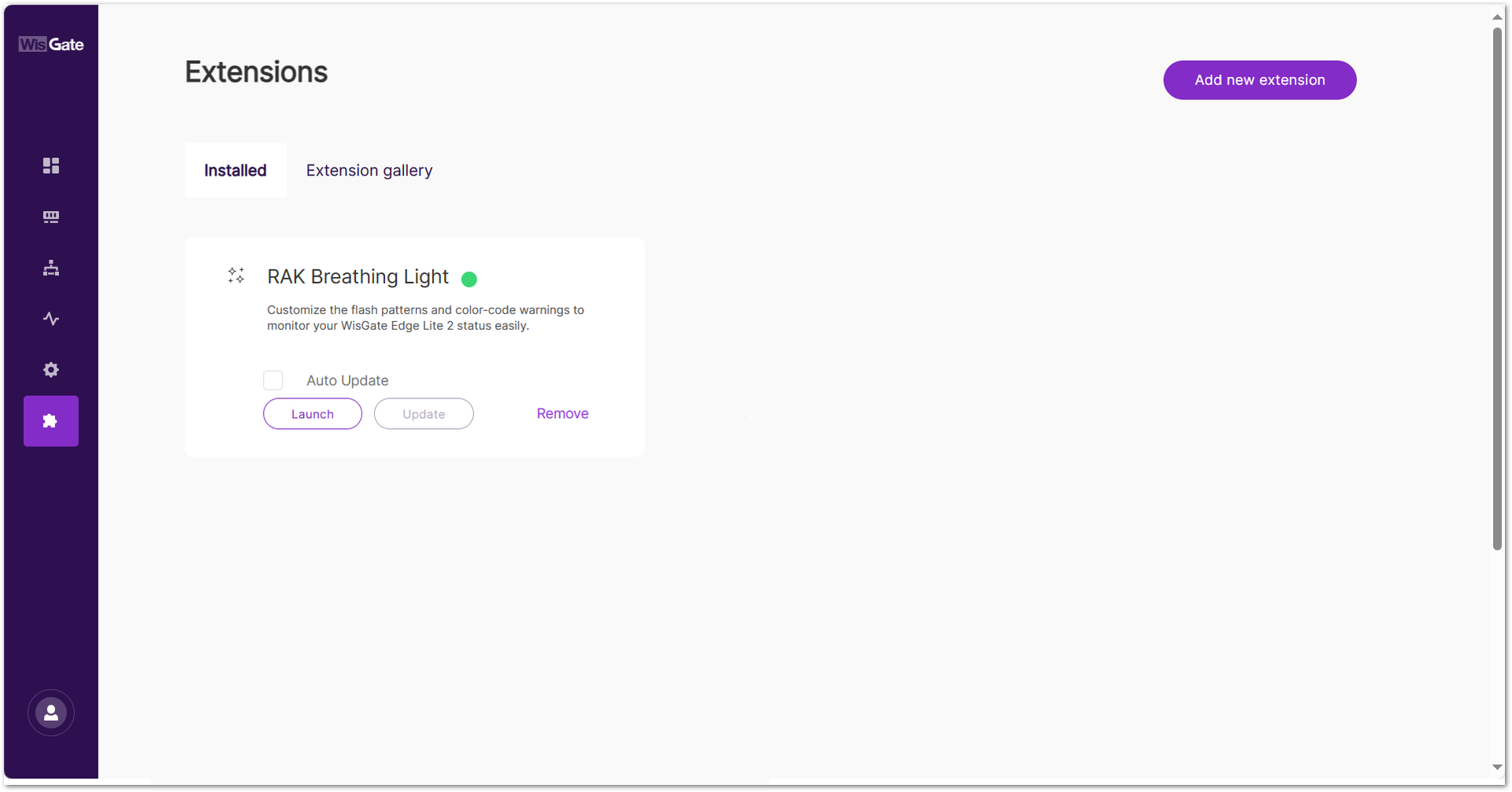 Figure 1: Launch the RAK Breathing Light Extension
- In the Configuration page, configure the mode, color, and blinking frequency of the LED.
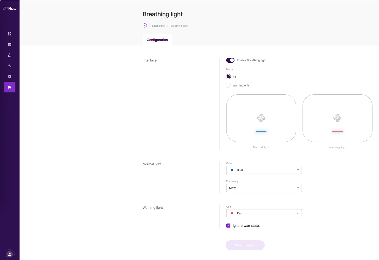 Figure 1: Configuration Page
-
Interface
- Enable Breathing Light: Enables or disables the breathing light extension.
- Mode: Sets the mode of the extension.
- All: The Normal light is enabled.
- Warning only: Disables the Normal light settings and only Warning light will glow.
-
Normal light: The settings for the normal light.
- Color: The color of the light (red, green, blue).
- Frequency: Blink frequency of the led (slow, fast, steady).
NOTEThe Normal light settings are disabled if Warning only mode is selected.
-
Warning Light: The color of the warning light.
-
Ignore wan status: When this option is enabled, the breathing light no longer monitors the WAN interface status.
In this mode, WAN connectivity changes (such as Ethernet hot-plug events or Cellular/Wi-Fi disconnections and reconnections) do not trigger a breathing light color change. The breathing light only reflects system states unrelated to the WAN interface.
Therefore, if the WAN status changes but the breathing light remains unchanged, this is expected behavior and does not indicate a malfunction.
- Once done with the configuration, click Save changes. You can check the status of the LED on the gateway itself.
RAK Custom Logo
The Custom Logo extension allows you to upload your logo in the Web UI. This extension is universally compatible with all gateways running WisGateOS 2. It was developed with both small or bigger enterprises in mind, allowing them to have their logo recognized and used in their daily operations.
Having the capability to rebrand your Web UI is essential for companies that need to effectively promote and visualize their brand or product. This necessity is met by RAKWireless' white label feature, which allows clients to customize the user interface to reflect their branding elements seamlessly.
Size and Format Requirements
The uploaded logo image must be in .svg format and cannot exceed 300 kb. You can preview the Web UI page before finally switching RAKWireless' logo with your brand logo.
Install the RAK Custom Logo Extension
To install the extension, follow the steps in How to Add an Extension section.
Configure the RAK Custom Logo Extension
- To access the RAK Custom Logo extension, click Launch.
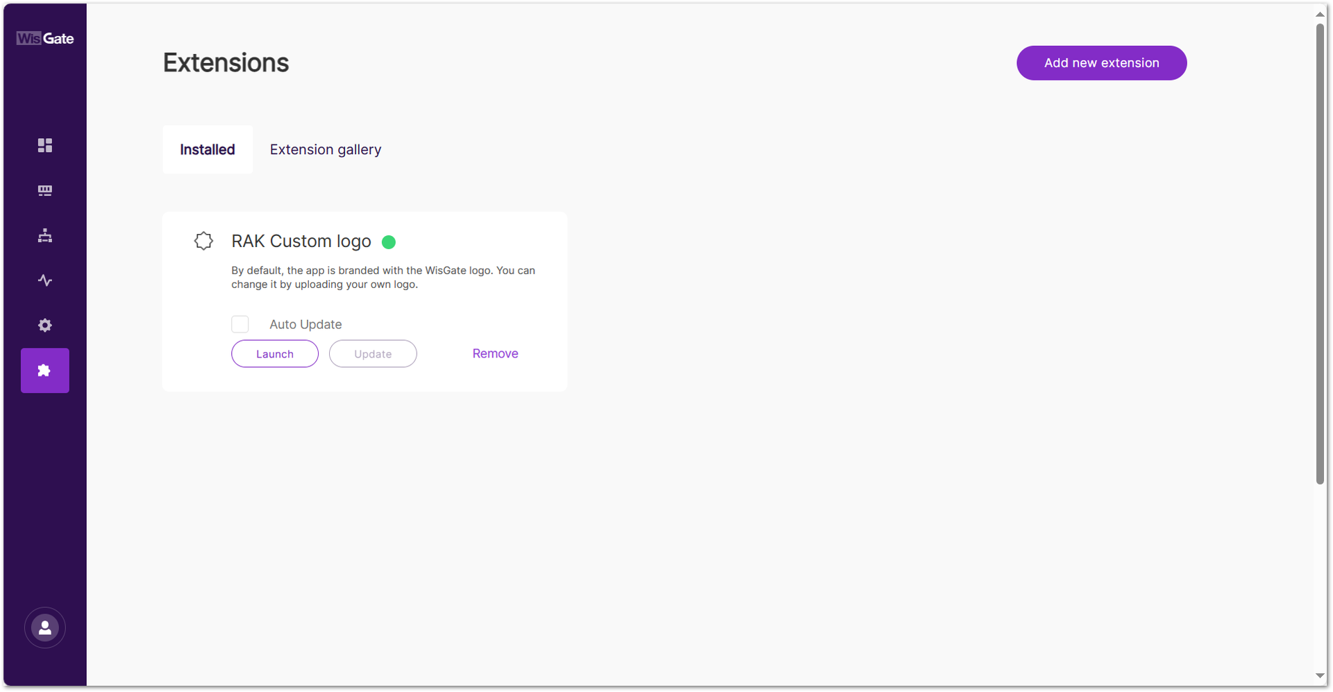 Figure 1: Launch the RAK Custom Logo Extension
- In the Configuration page, you can set a custom logo on the login page and on the sidebar menu.
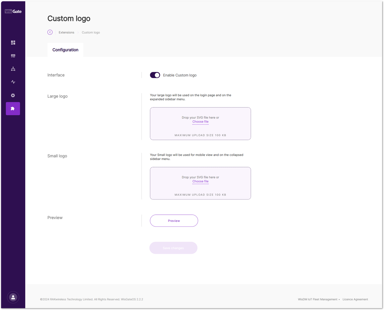 Figure 1: Configuration Page
- Interface: Enables/disables custom logo extension.
- Large logo: This logo will be used on the login page and the expanded sidebar menu. Upload a logo by dragging and dropping it, or by clicking Choose File to browse manually.
- Small logo: This logo will be used for mobile view and the collapsed sidebar menu. Upload the logo by dragging and dropping it, or by clicking Choose File to browse manually.
- Preview: After selecting the images, click Preview to see how the logo appears on the login page and sidebars in both desktop and mobile views.
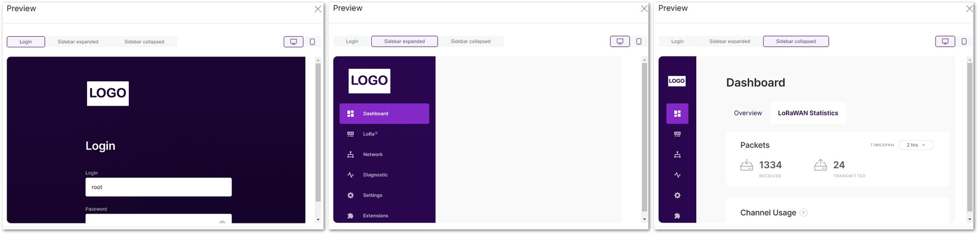 Figure 1: Logo Preview for Desktop Users
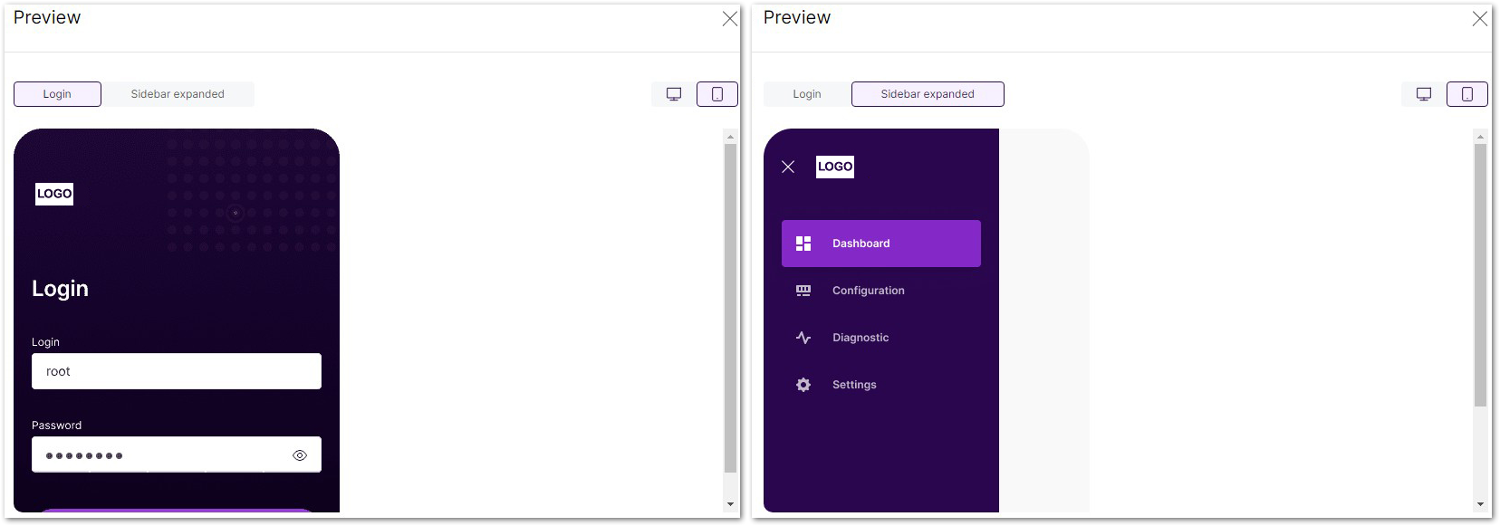 Figure 1: Logo Preview for Mobile Users
- To apply the selected logos, click Save changes. The page reloads automatically, applying the selected logos.
RAK Country Settings
LBT (Listen Before Talk) means that, before transmitting, the gateway checks the availability of the channel. This is necessary because LoRaWAN is a multi-channel protocol and uses ISM Band. Anyone can use the band, so a collision occurs if two or more end devices send signals simultaneously.
The gateway checks for empty channels and uses one of them to send downlink data. If a channel is occupied, the gateway performs a random back off. In case all of the channels are occupied, the gateway waits for a free channel and tries to send the downlink data again.
LBT is usually governed by regulations per country. In WisGateOS 2 2.x, there is a country table which includes proper configurations for all countries so you can set the country code in WisGateOS 2 2.x.
AS923 end-devices operating in Japan shall perform Listen Before Talk (LBT), based on ARIB STD-T108 regulations. The ARIB STD-T108 regulation is available for free and should be consulted as needed.
You can switch the frequency plan in the following regions:
- AS923, KR920
- EU868, RU864, IN865
- CN470
The frequency plan will be limited to a particular region. Tx power will be limited to under the maximum.
- Downlink Tx Power
- Beacon Tx Power
Install the RAK Country Settings Extension
To install the extension, follow the steps in How to Add an Extension section.
Configure the RAK Country Settings Extension
- To access the RAK Country Settings extension, click Launch.
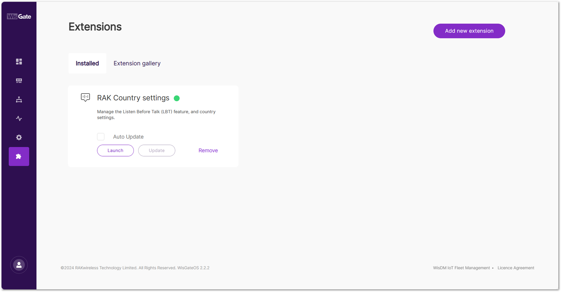 Figure 1: Launch the RAK Country Settings/LBT Extension
- In the Configuration page, click the Select your Country button to set your country.
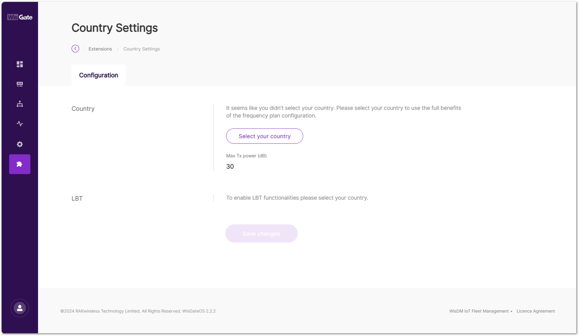 Figure 1: Country selection
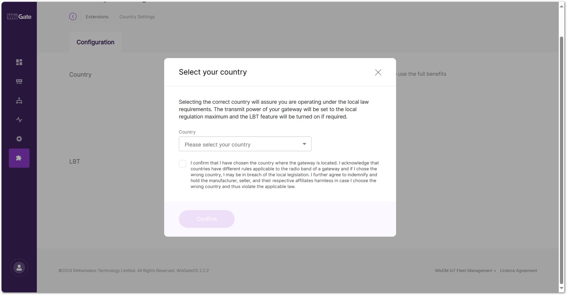 Figure 1: Find your country in the list
- In the new window, find your country and select it. Tick the checkbox below to confirm that you have chosen the country where the gateway is located. Then click Confirm to set the LBT for your country.
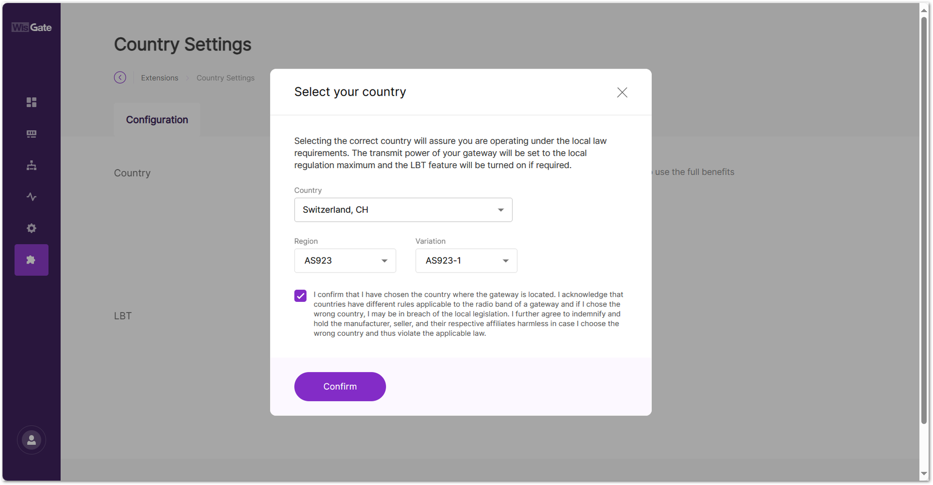 Figure 1: Confirm your country
- Enable the LBT by clicking on the Enable Listen Before Talk switch.
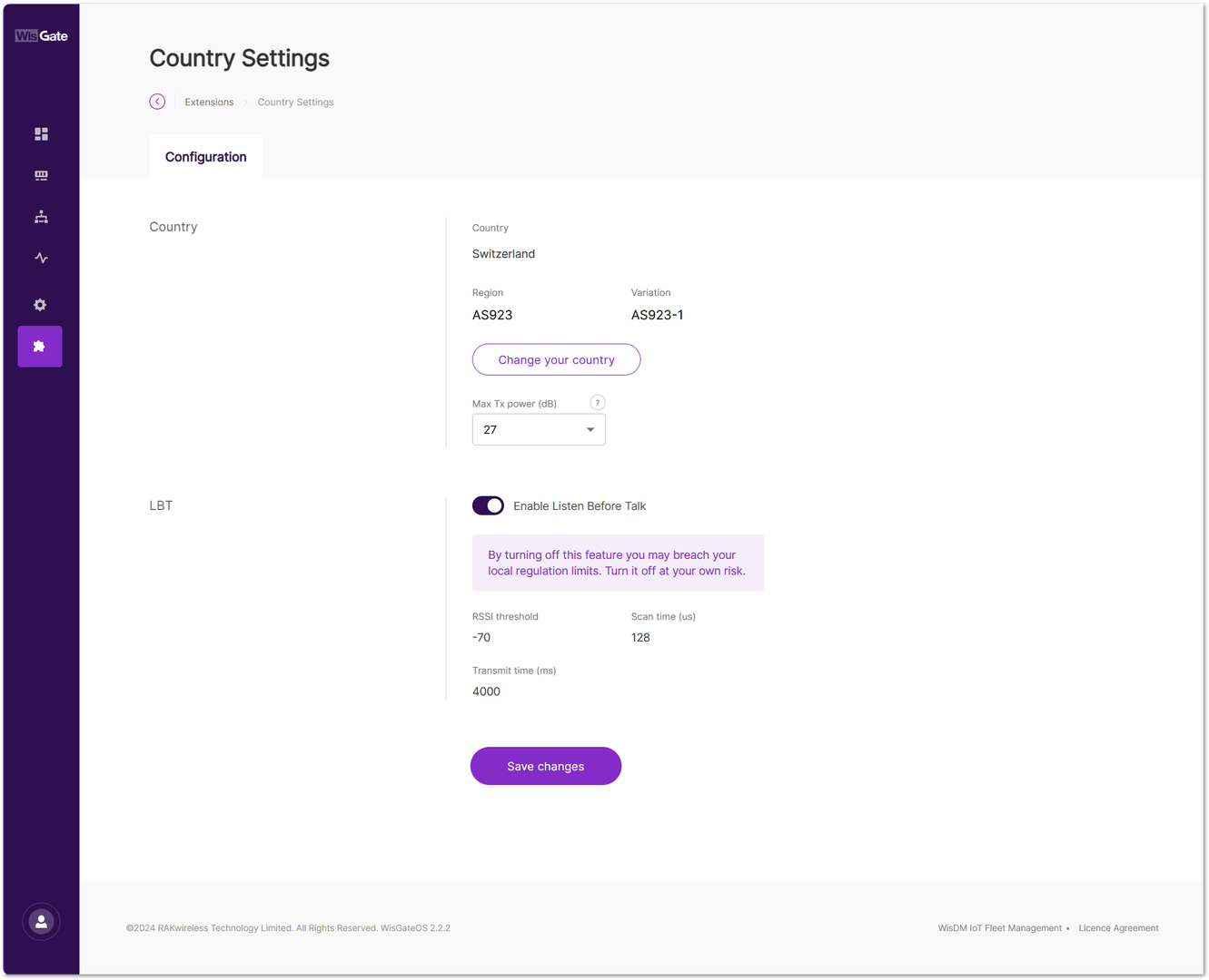 Figure 1: Enable LBT
- Click Save changes to apply the configuration. LBT is now enabled on your gateway.
RAK Open/Close Port
This extension allows you to add or delete packet traffic management rules on the gateway, allowing any (or specific) host IP from a designated subnet to communicate with the gateway through specified ports.
Install the RAK Open/Close Port Extension
To install the extension, follow the steps in How to Add an Extension section.
Configure the RAK Open/Close Port Extension
- To access the RAK Open/Close Port extension, click Launch.
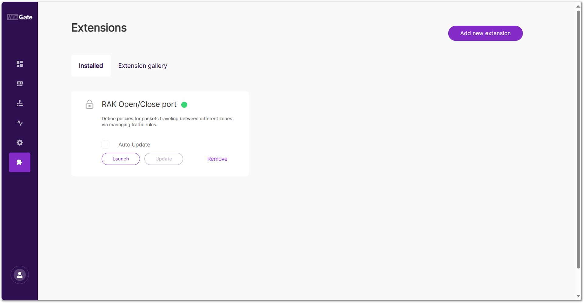 Figure 1: Launch the RAK Open/Close Port Extension
After clicking Launch, the Traffic rules page will be displayed, showing the default rules of the Open/Close port extension with the following parameters:
- Service name: A readable name for the service.
- Protocol: The protocol used.
- Family: The protocol version used for the traffic.
- From: External source
- To: Internal source
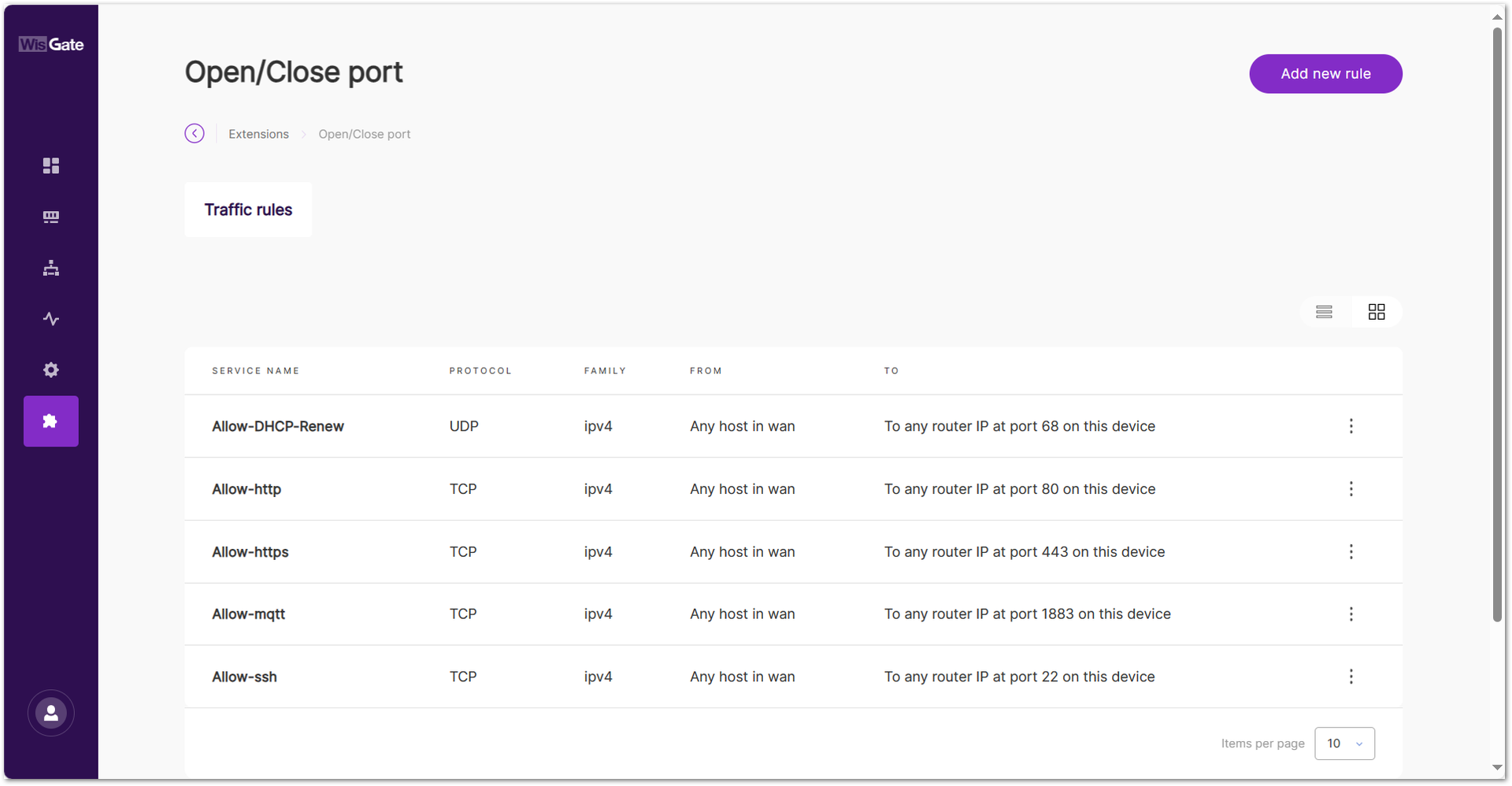 Figure 1: Traffic rules page
For example, the Allow-http service indicates that any host in WAN can communicate with the gateway through port 80 using the TCP protocol type.
Click ⋮ and select Delete to remove the traffic rule. After deleting, the UI may still appear accessible for a short time due to browser caching. Clear the browser cache or wait a few minutes for the firewall changes to take effect.
- To add a new rule, click the Add new rule and configure the following information:
- Service name: Provide a readable name for the rule.
- Protocol: Select the protocol used for the rule:
- TCP
- UDP
- TCP + UDP
- Sources:
- Allow any host: Allows any host to access the rule.
- Source IP address: Specify up to three host IPs.
- Destination port: The destination port for routing.
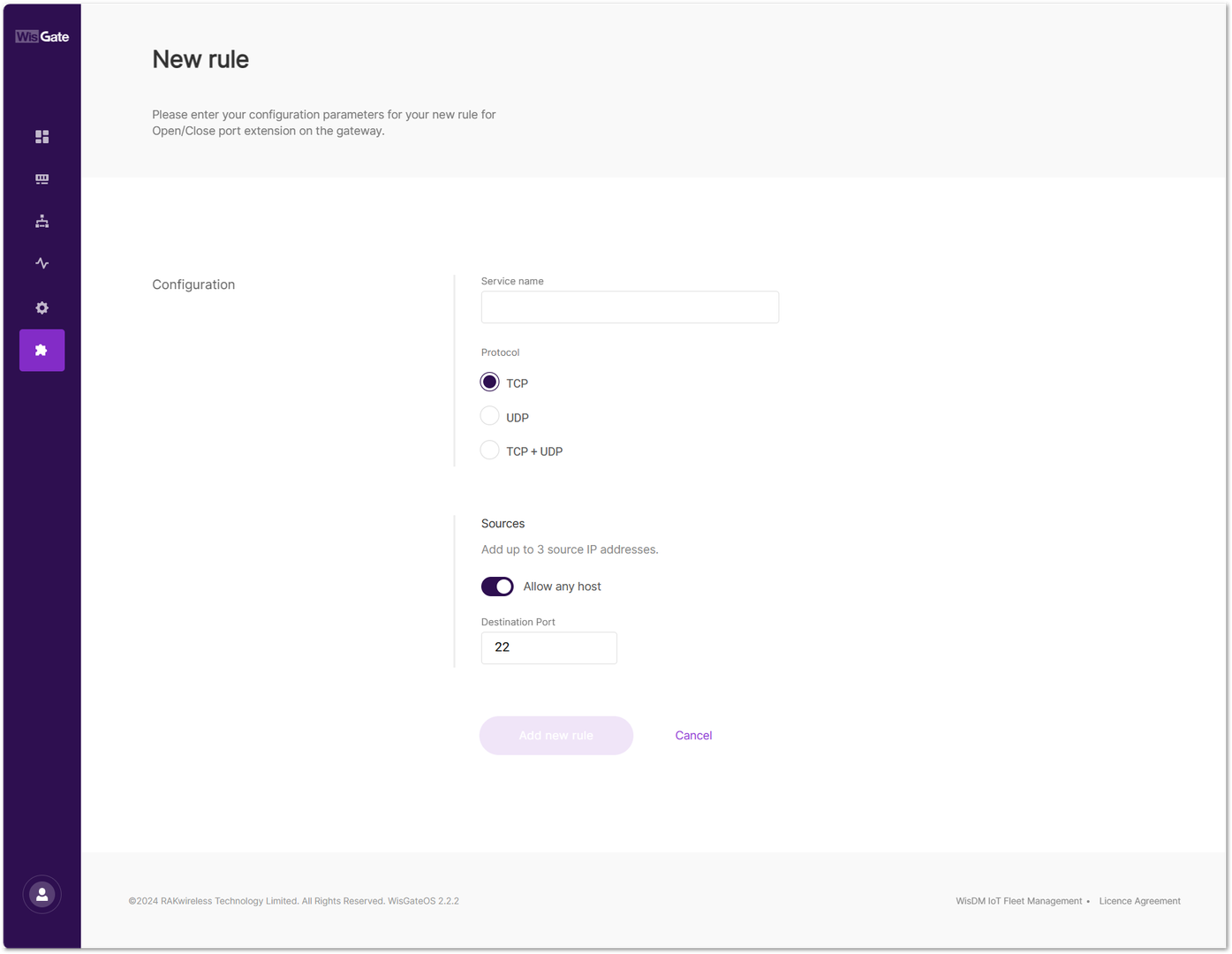 Figure 1: Add a new rule
- To save the changes, click Add new rule. The newly created rule will then appear in the Traffic rules interface.
RAK Solar Battery
The RAK Solar Battery extension is used to display the operational status information of the solar battery used by the gateway. This includes information on the performance of the solar battery, battery health status, cycle period, battery capacity, charging and discharging modes, and more.
This extension is compatible with the following gateways:
- RAK7240V2
- RAK7267
- RAK7289V2
- RAK7285
You can learn the status of the solar battery in real-time through the UI interface.
Install the RAK Solar Battery Extension
To install the extension, follow the steps in How to Add an Extension section.
Enable and View Solar Battery Monitoring
- To access the RAK Solar Battery extension, click Launch.
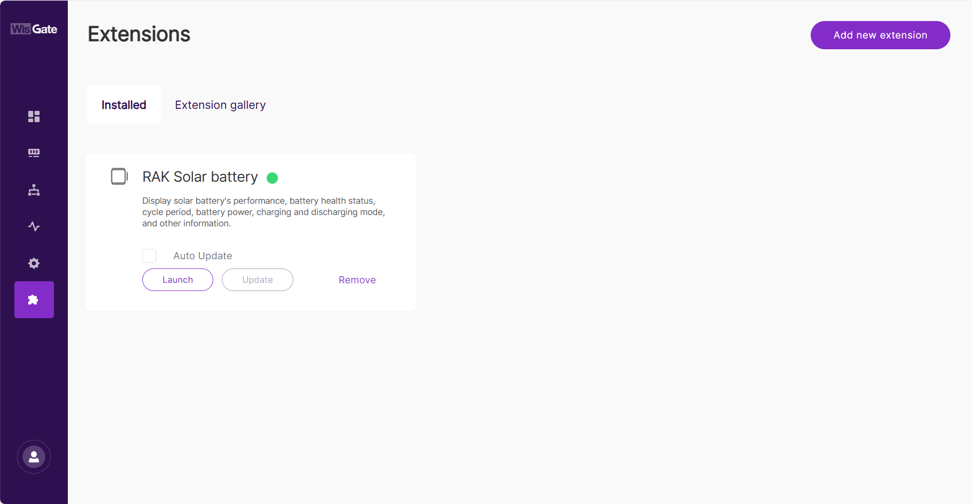 Figure 1: Launch the RAK Solar Battery Extension
- Enable the switch to activate Monitor solar battery.
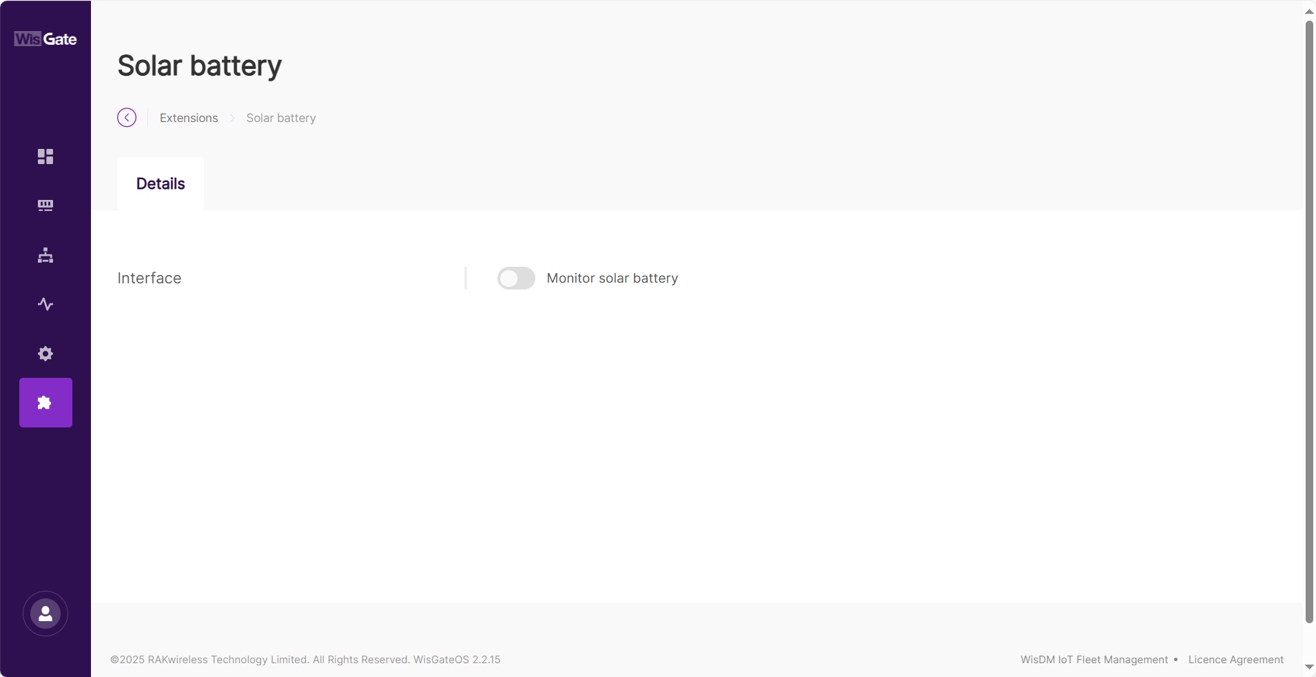 Figure 1: Overview page
- When the confirmation window pops up, click Enable monitoring to activate the feature.
- In the Details page, you can view information about the Solar Battery.
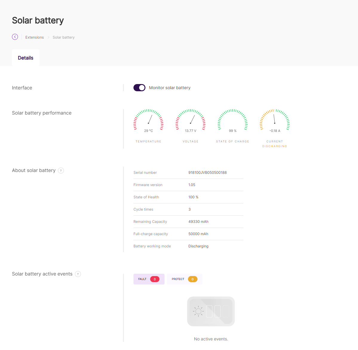 Figure 1: Details page
- Solar battery performance: Shows the real-time performance of the battery.
- Temperature: The temperature of the battery. Used to prevent overheating or freezing.
- Voltage: The voltage level of the battery.
- State of charge: The current battery level.
- Current: Indicates whether the battery is charging or discharging.
- About solar battery: Contains additional information about the battery.
- Serial number: A unique identifier for the battery.
- Firmware version: The software version of the battery management system.
- State of Health: Represents the battery's overall condition.
- Cycle times: The number of charge/recharge cycles.
- Remaining Capacity: The current available capacity of the battery.
- Full-charge capacity: The maximum capacity when the battery is fully charged.
- Battery working mode: Indicates whether the battery is charging or discharging.
- Solar battery active events: Notifies users about battery-related issues.
- FAULT: The system detects a potentially damaged battery and recommends immediate replacement.
- PROTECT: The system detects a serious issue and shuts down the battery as a protective measure. Once conditions are safe, the battery resumes operation automatically.
- No active events: Indicates that the battery is operating normally without issues.
To display the Serial number and Firmware version of the solar battery, the following conditions must be met:
- The battery must be running firmware v1.0.4 or later.
- The Solar Battery extension must be updated to the latest version.
- When using WisGateOS 2.2.15 or later, both Serial number and Firmware version are shown.
- When using earlier versions of WisGateOS 2, only the Firmware version is shown, while the Serial number appears as N/A.
RAK WireGuard
WireGuard is a simple but fast VPN. It aims to be faster, simpler, and leaner than the IPsec protocol. It intends to be more performant than the well-known RAKwireless - OpenVPN. Before, it was not possible to use the WireGuard protocol on the RAKwireless gateways, but that is not the case now.
The new WisGateOS 2 now offers Extension features, where you can install and set up the WireGuard extension. In this tutorial, you will learn how to set the WireGuard client on the gateway.
This guide assumes that you have some knowledge in setting up a WireGuard server and have a WireGuard server set up.
Install the RAK WireGuard Extension
To install the extension, follow the steps in How to Add an Extension section.
Configure the RAK WireGuard Extension
- To access the RAK WireGuard extension, click Launch.
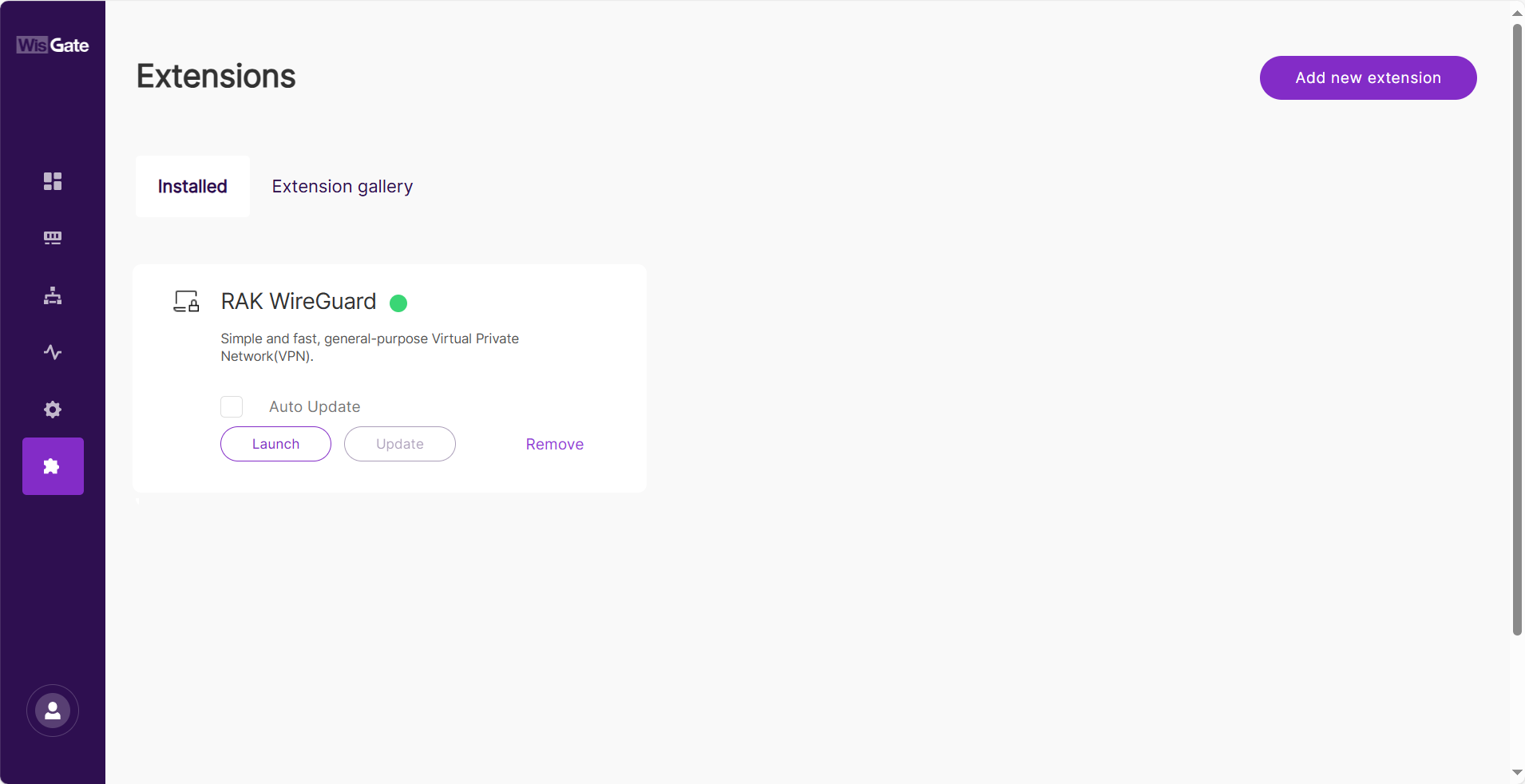 Figure 1: Launch the RAK WireGuard Extension
- In the Configuration page, enable the Enable WireGuard switch and configure the following information:
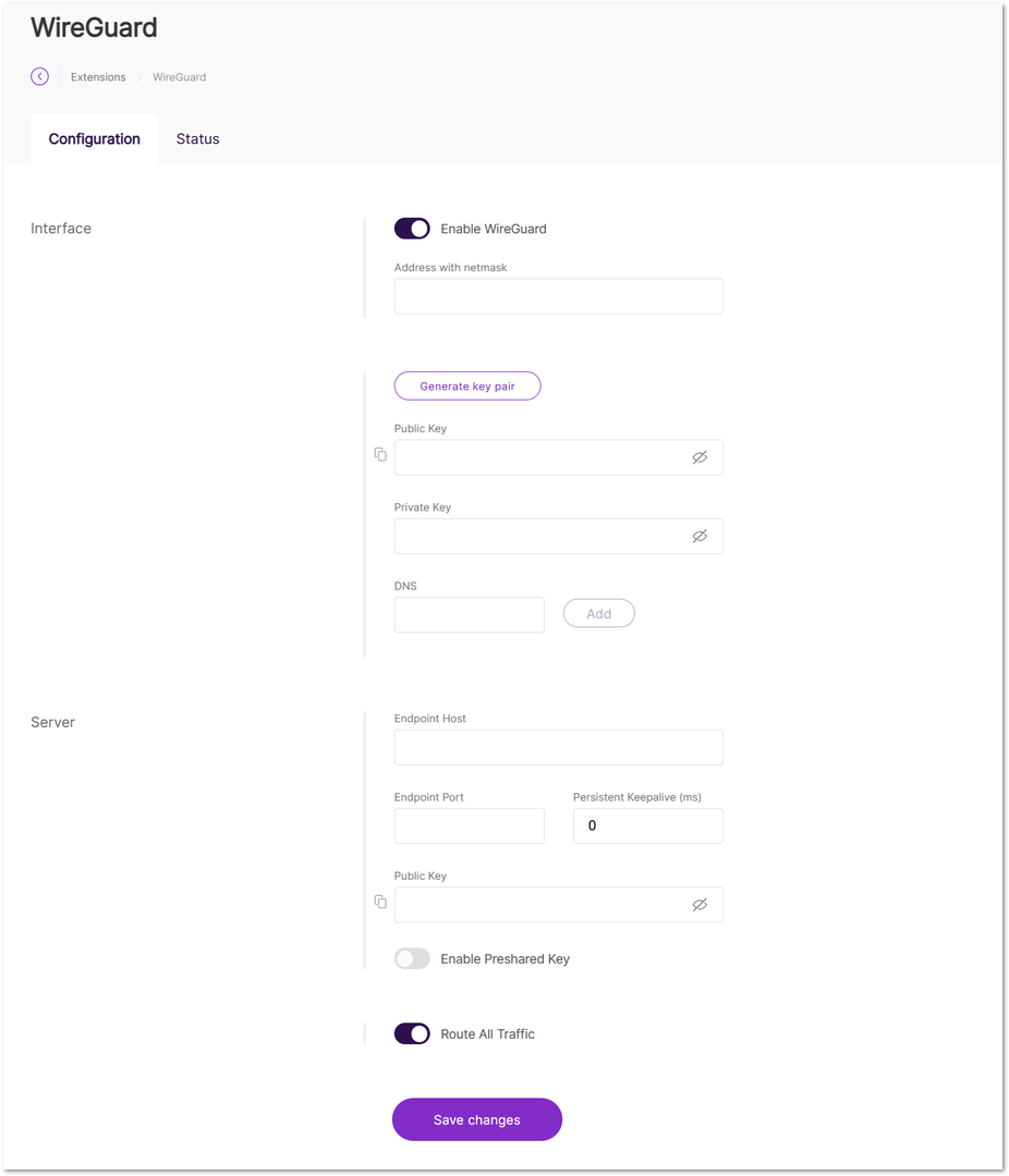 Figure 1: Configuration page
-
Interface: Settings for the WireGuard client.
- Address with netmask: The IP address the WireGuard client will use. It must be in the same range (e.g.,
10.0.8.0to10.0.8.255) defined by the server. - Generate key pair: Automatically generates the key pair.
- Public Key: The public key of the WireGuard client.
- Private Key: The private key of the WireGuard client.
NOTE
Do not share your private key with anyone.
- DNS: The DNS server used by the client.
- Address with netmask: The IP address the WireGuard client will use. It must be in the same range (e.g.,
-
Server: Settings for the WireGuard server.
-
Endpoint Host: The IP address of the machine or cloud instance where the WireGuard server is hosted.
-
Endpoint Port: The port used for WireGuard traffic.
-
Persistent Keepalive (ms): The interval for sending keepalive packets to maintain the connection.
-
Public Key: The public key of the WireGuard server.
-
Enable Preshared Key: Enables the preshared key field. The preshared key is part of the Noise protocol used to establish an encrypted connection between peers.
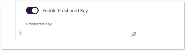 Figure 1: Enable preshared key
-
-
Route All Traffic: Allows traffic from all IPs.
- Allowed IPs: Specifies the IPs that are allowed to connect to the gateway via the WireGuard IP. This option is only available when Route All Traffic is disabled.
- To save the changes, click Save changes.
NOTE
Remember to add the WireGuard Client credentials to the WireGuard server configuration.
- After the connection is established, open the Status tab to view the WireGuard connection.
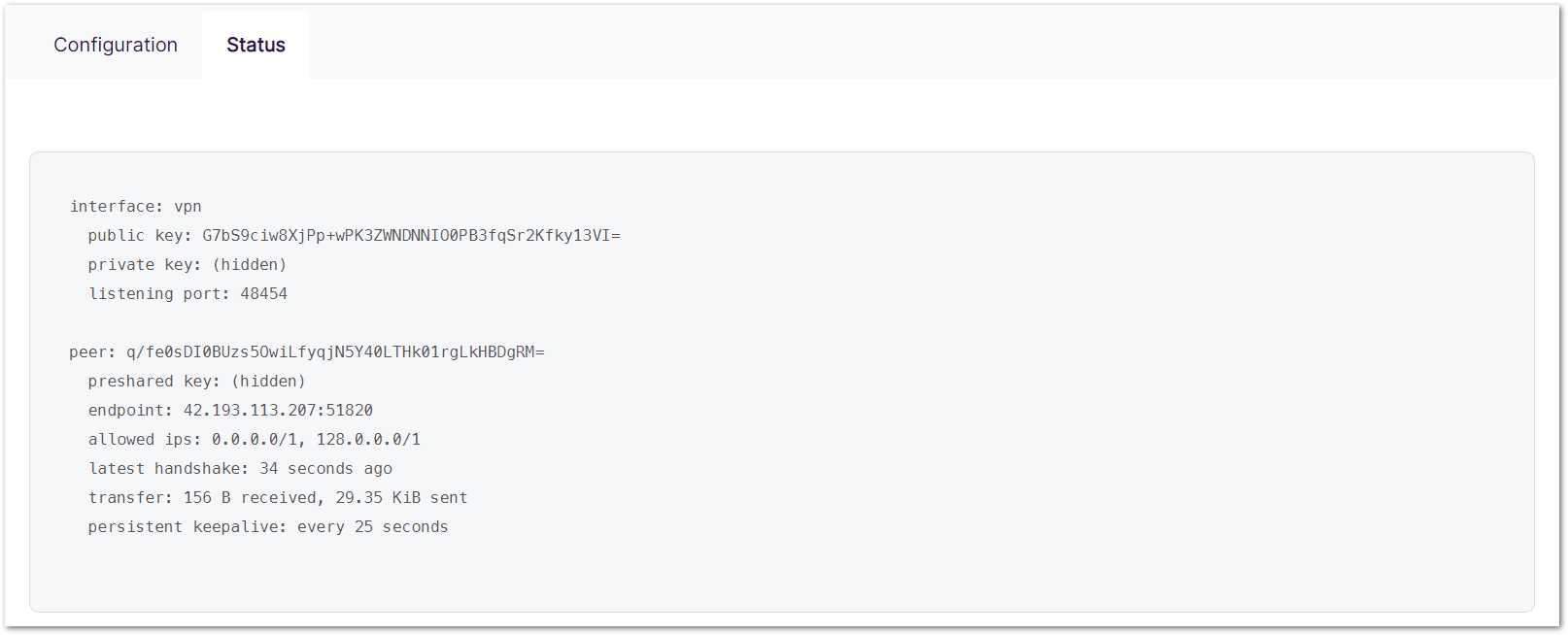 Figure 1: WireGuard status
RAK OpenVPN Client
OpenVPN (Open Virtual Private Network) is a type of VPN in which a server is deployed to allow both the Gateway and multiple client devices, such as PCs, phones, and other endpoints, to connect via a public IP address. This setup can be implemented using any backhaul connectivity supported by the gateway, including Ethernet, Wi-Fi, or LTE. When using LTE as the backhaul, make sure that the gateway has a static public IP address.
By connecting to the OpenVPN server from a remote client, the gateway can be securely managed from anywhere, at any time. As mentioned above, an OpenVPN server is required. Detailed instructions for deploying a server in the AWS cloud can be found in the How to Configure WisGate Edge v2 Gateways Remote Management - OpenVPN guide.
Install the RAK OpenVPN Client Extension
To install the extension, follow the steps in How to Add an Extension section.
Configure the RAK OpenVPN Client Extension
Make sure you have local network access to your gateway and connect to it to access the Web UI.
- To access the RAK OpenVPN Client extension, click Launch.
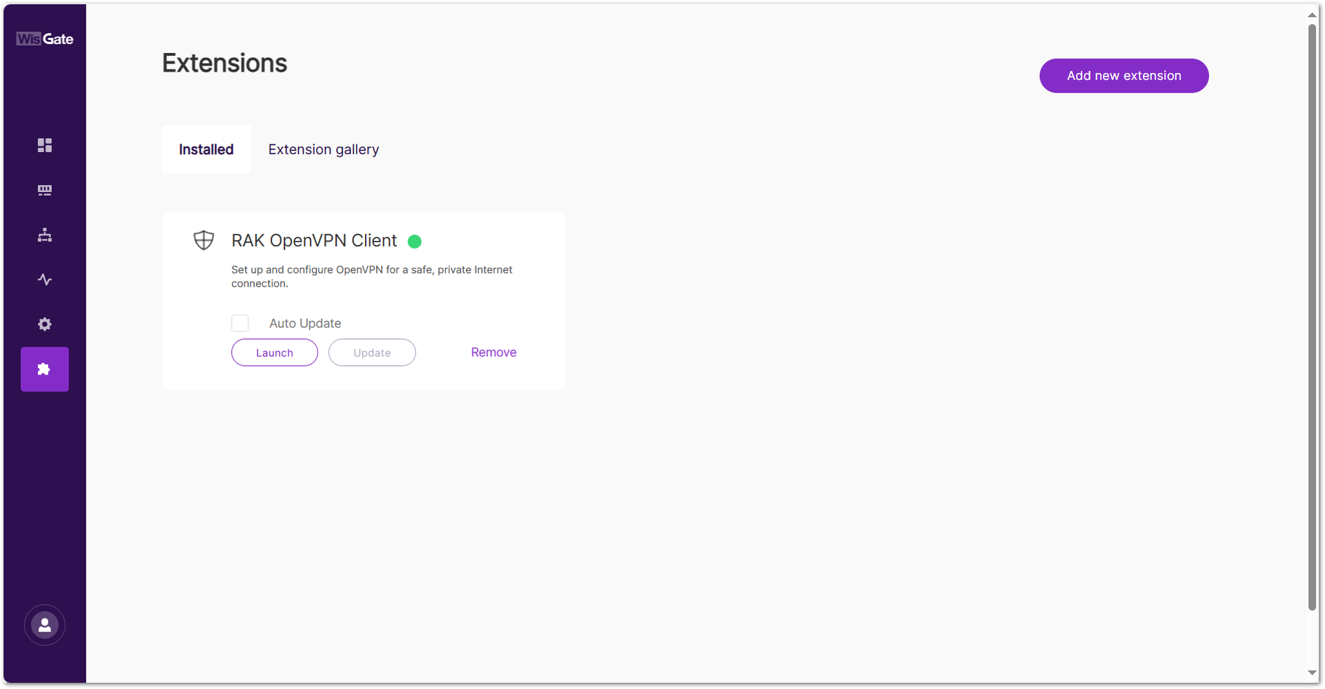 Figure 1: Launch the RAK OpenVPN Client Extension
- Add an OpenVPN tunnel by clicking the Add tunnel button or the add one now link.
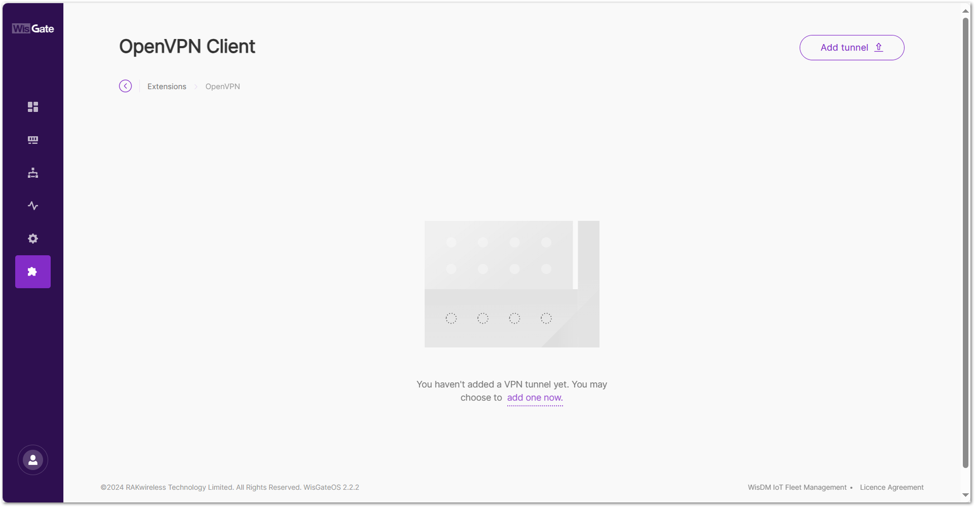 Figure 1: Add OpenVPN tunnel
- Click the choose file link and browse for the
.ovpnfile or drag and drop the.ovpnfile you created by following the How to Configure WisGate Edge v2 Gateways Remote Management - OpenVPN guide.
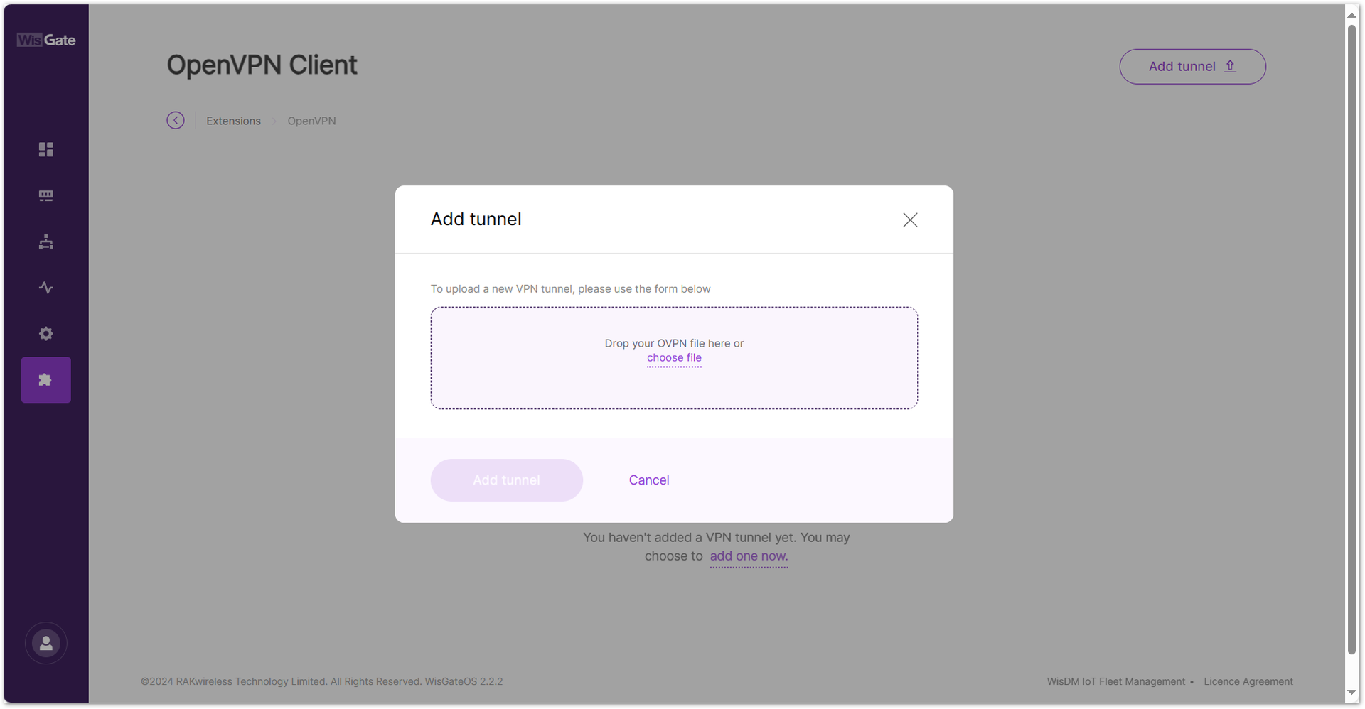 Figure 1: Add .ovpn file to the gateway
- Once the file is added, click Add tunnel to add the OpenVPN tunnel.
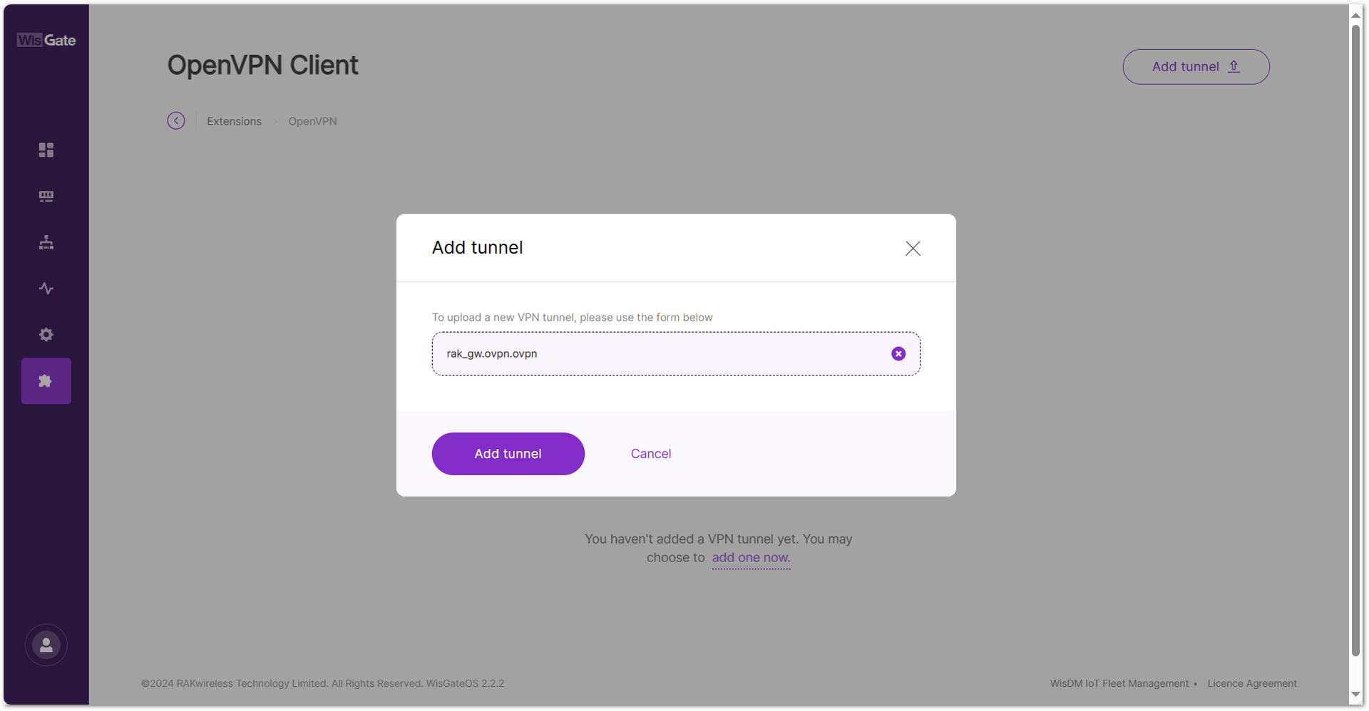 Figure 1: Add OpenVPN tunnel
When the tunnel is added successfully, a confirmation message will appear at the bottom of the screen.
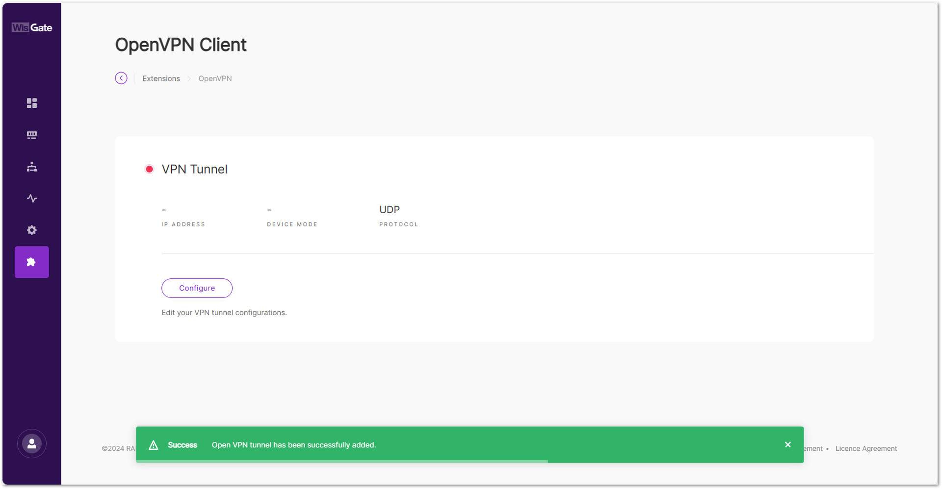 Figure 1: Successfully added tunnel
- Click the Configure button of the VPN tunnel. On the next window, toggle the Enable Connection switch to enable the OpenVPN tunnel and click Save changes.
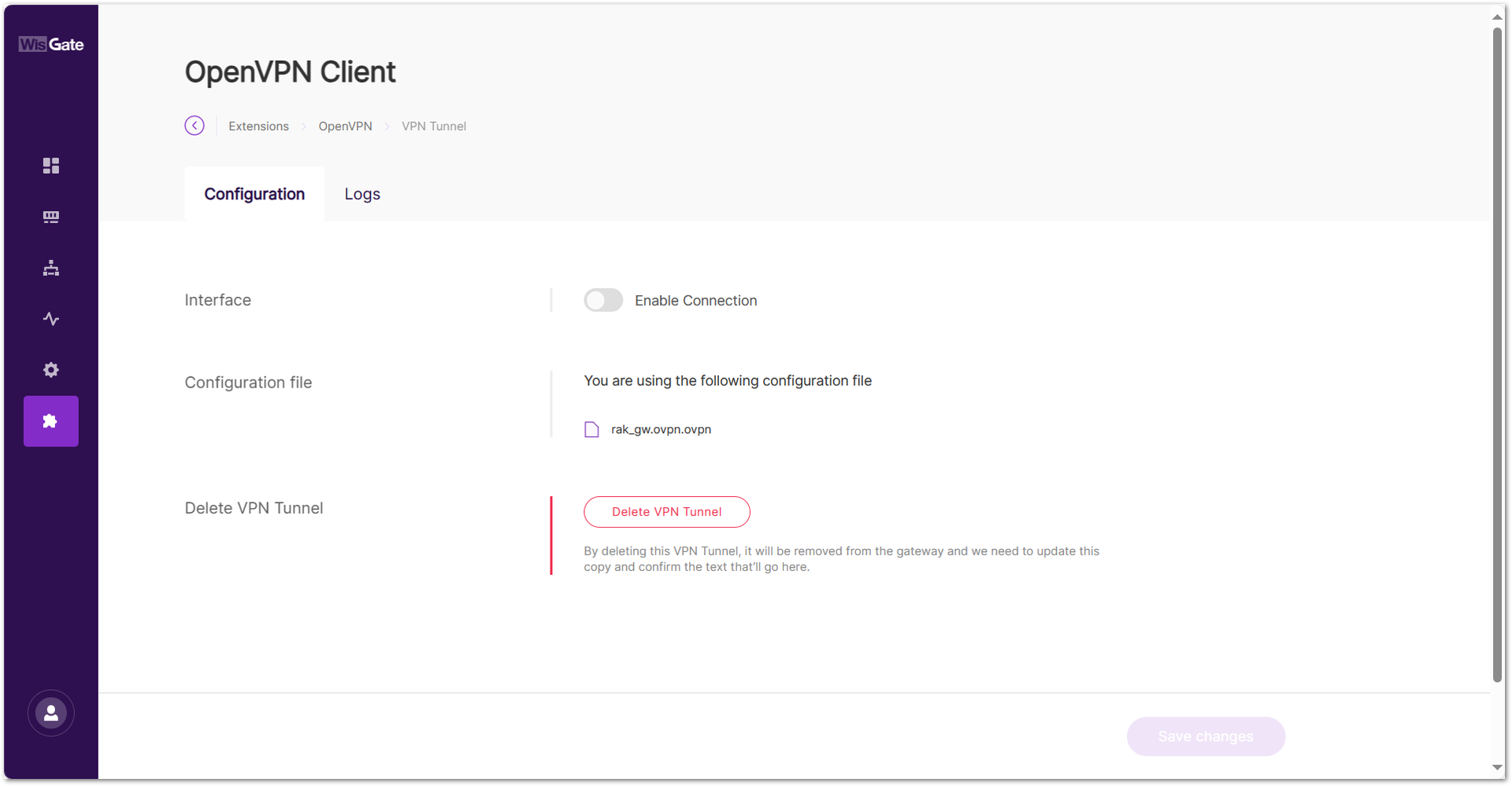 Figure 1: Start the OpenVPN tunnel
Verify the Configuration
- You can check the OpenVPN tunnel status under the Logs tab.
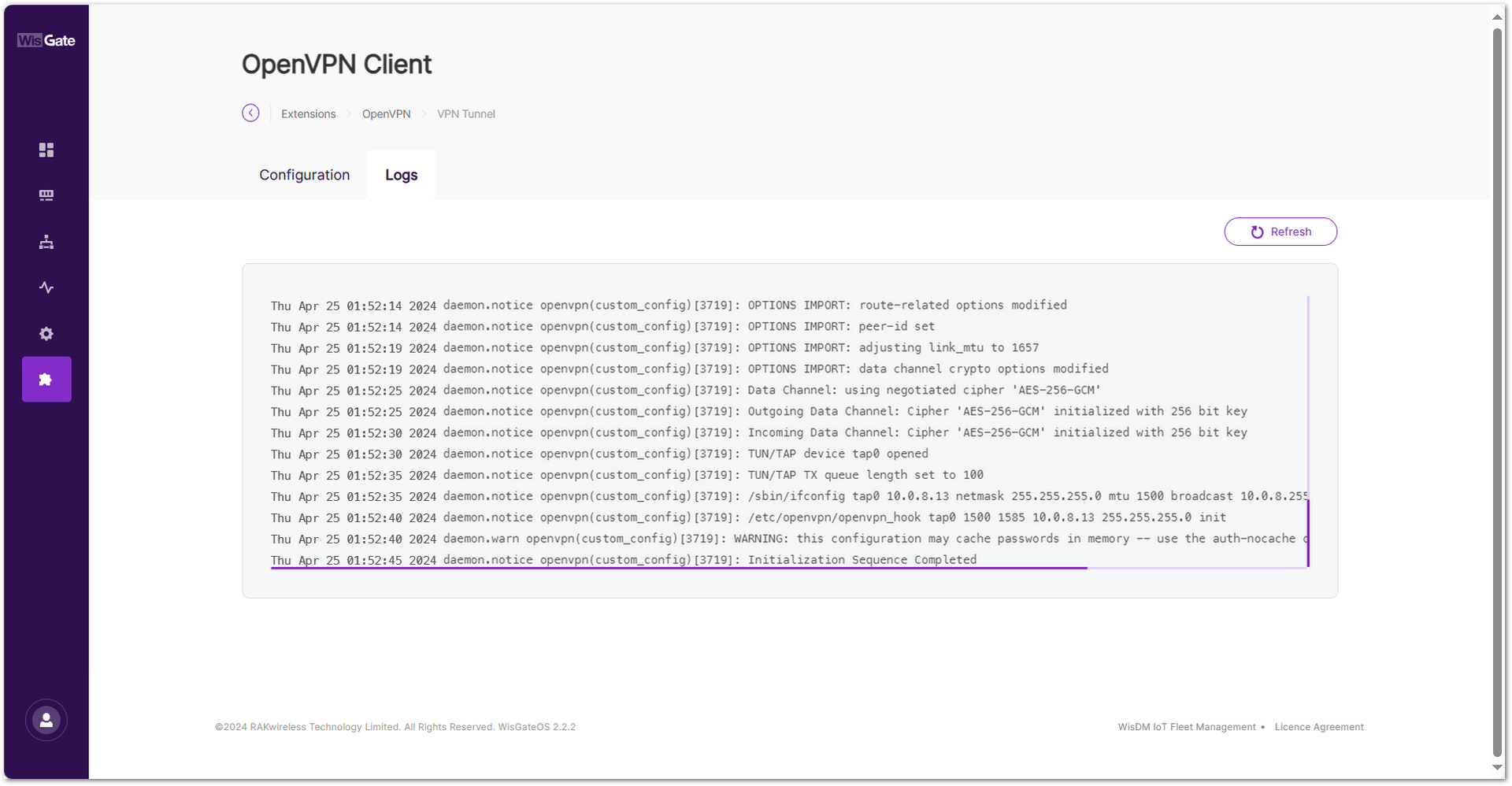 Figure 1: OpenVPN tunnel status
- You can view the assigned IP address on the OpenVPN Overview page.
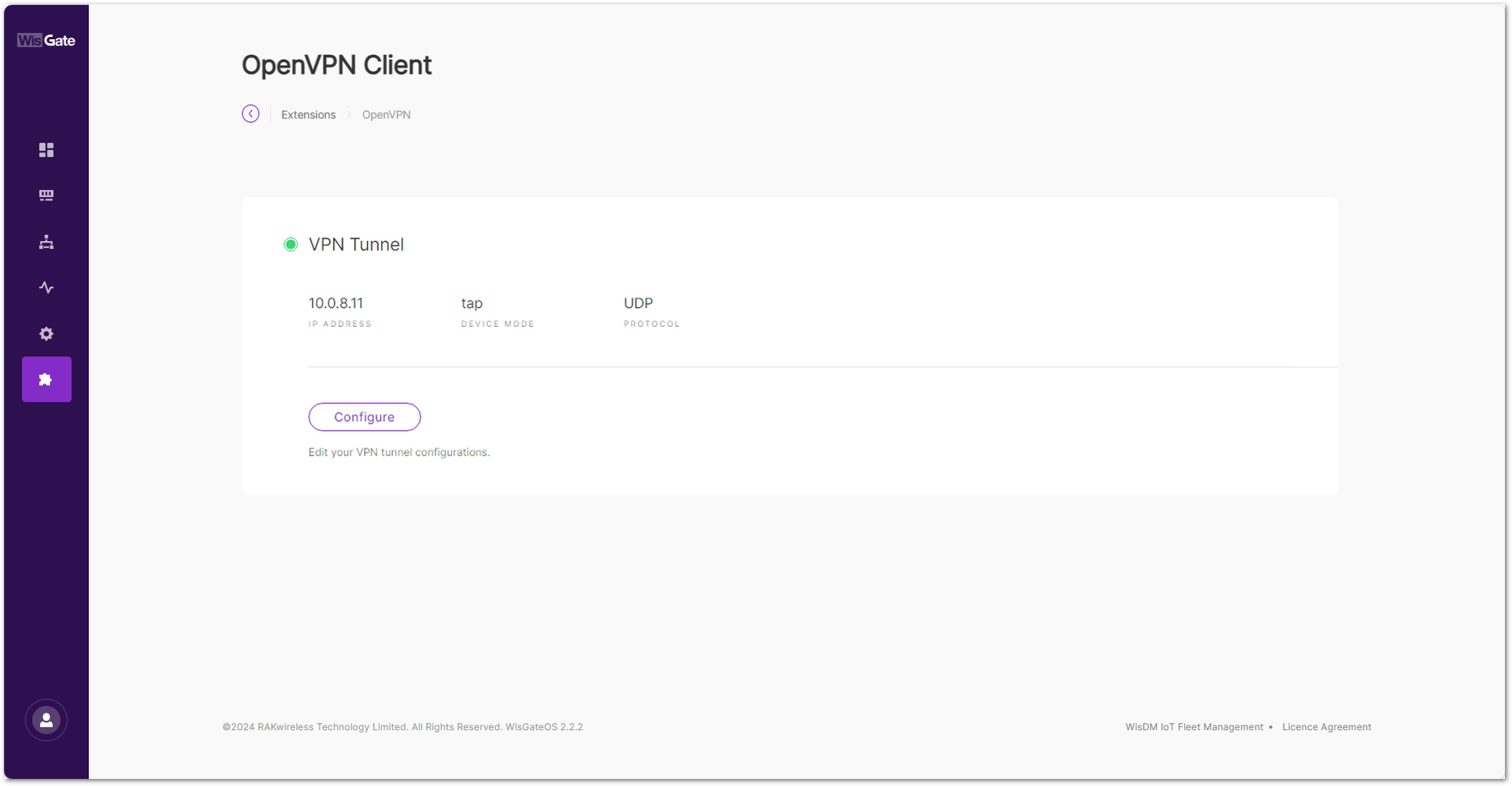 Figure 1: OpenVPN assigned IP
Operation and Maintenance
The Operation and Maintenance extension is operation and maintenance tool that features scheduled device reboot and monitoring of the 4G network status. If the 4G network connection is lost, it automatically restarts the cellular module to recover the connection.
This extension is only compatible with WisGateOS 2 2.2.x and later.
Install the Operation and Maintenance Extension
To install the extension, follow the steps in How to Add an Extension section.
Configure the Operation and Maintenance Extension
- To access the Operation and Maintenance extension, click Launch.
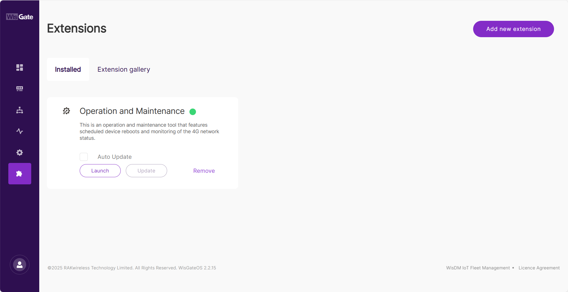 Figure 1: Launch the Operation and Maintenance Extension
- On the Configuration page, configure cellular network monitoring and set a reboot schedule.
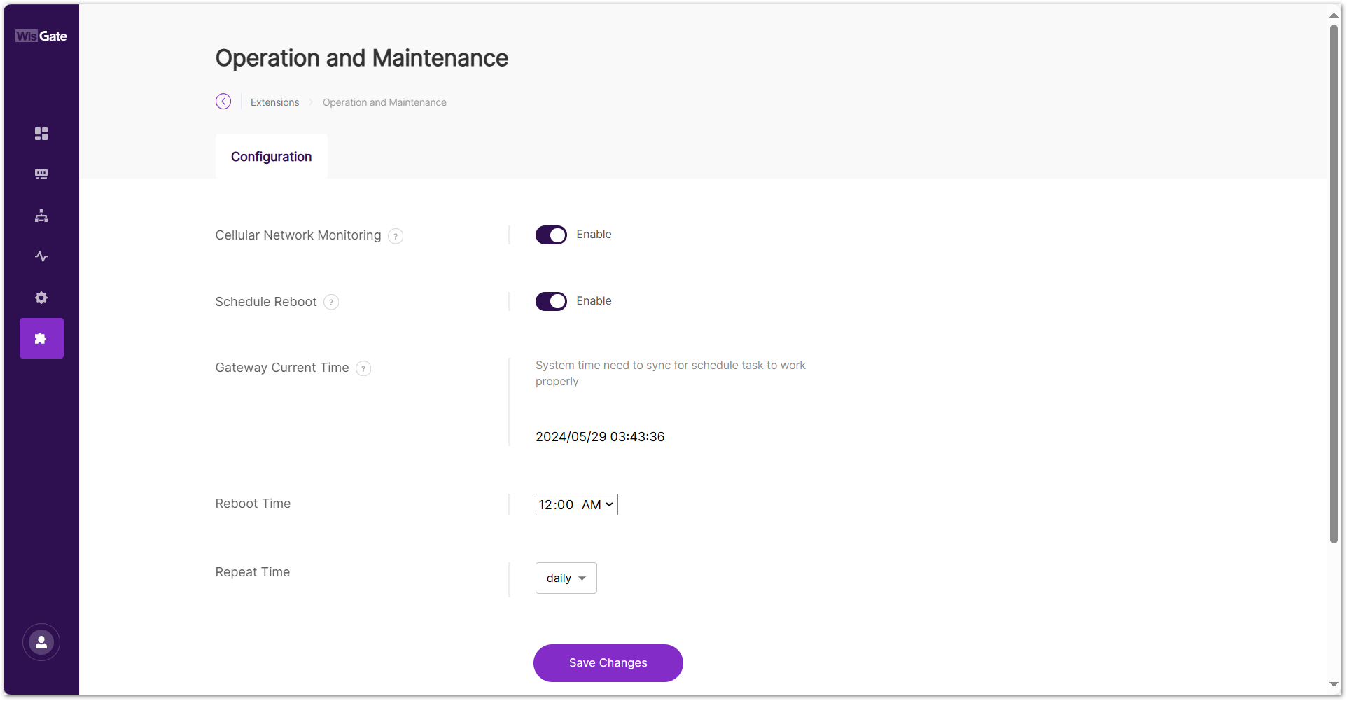 Figure 1: Configuration page
- Cellular Network Monitoring: When enabled, the gateway will monitor the cellular connection status every 2 minutes. If the 4G network connection is lost, it will automatically restart the cellular module to restore the connection.
- Schedule Reboot: When enabled, the gateway will reboot periodically based on the configured schedule.
- Gateway Current Time: The system time must be synced for scheduled tasks to function properly. To change the current time, go to User Preferences and set the time.
- Reboot Time: The time when the gateway will reboot.
- Repeat Time: The reboot cycle interval.
- To save the changes, click Save changes.
Field Test Data Processor
The Field Test Data Processor Extension is a gateway-side application for local LoRaWAN field test data processing. Installed on a RAK WisGateOS 2 gateway, it connects to the LoRaWAN Network Server (LNS) through MQTT, receives uplink metadata from Field Tester devices, and calculates key link-quality metrics such as RSSI, SNR, and packet-loss rate.
The processed results can be sent back to supported Field Tester devices through downlink feedback and can also be used on the gateway for real-time heatmap visualization, network-parameter review, and CSV data export.
The extension supports the Built-in LNS on RAK gateways, as well as third-party LNS platforms such as ChirpStack v3 / v4, TTN, TTI, and AWS IoT Core. It can also support multiple Field Tester devices in the same deployment, enabling centralized gateway-side processing and analysis across different test points.
For Field Tester devices with an on-device reporting interface, part of the processed results may also be displayed directly on the device. In all cases, the extension acts as the gateway-side data processing component for local signal-quality analysis without relying on external cloud services.
This extension is compatible with WisGateOS 2 v2.2.x and later.
Field Test Data Processor Extension Parameter Definitions
| Name | Description |
|---|---|
| Device EUI | The unique identifier of the Field Tester Plus device currently being analyzed. |
| RSSI Chart | Received Signal Strength Indicator. Shows the signal strength of uplink packets received by the gateway. Measured in dBm. Closer to 0 = stronger signal. |
| SNR Chart | Signal-to-Noise Ratio. Indicates how much stronger the signal is compared to background noise. Higher values represent better communication quality. |
| DateRate | The LoRaWAN Data Rate (DR) used for the uplink. Lower DR values offer longer range but lower data throughput. |
| Region | Frequency band used by the Field Tester Plus (e.g., EU868, US915). Must match the configuration of the connected gateway. |
| Loss Rate | Uplink packet loss rate, calculated based on gaps in frame counters. Ideally should be 0%. |
| Last Time | Timestamp of the last successfully processed uplink. Useful for checking if the device is still active. |
| Label | A user-defined location tag for the current test point (e.g., 3F-Elevator). This label will appear in exported CSV reports. |
| No. of Gateway | Number of gateways that received the latest uplink. |
| Gateway EUI | The unique identifier of the gateway that received the latest uplink (typically the nearest or strongest gateway). |
| Distance | Estimated distance (in meters) between the device and the gateway. Requires GPS on the device. |
Install the Field Test Data Processor Extension
To install the extension, follow the steps in How to Add an Extension section.
Configure the Field Test Data Processor Extension
Configure the Field Test Data Processor Extension based on the LoRaWAN Network Server currently connected to your gateway. The extension communicates with the selected LNS through MQTT, so you need to follow the corresponding configuration steps for your network server type.
Built-in Network Server
- To access the Field Test Data Processor extension, click Launch.
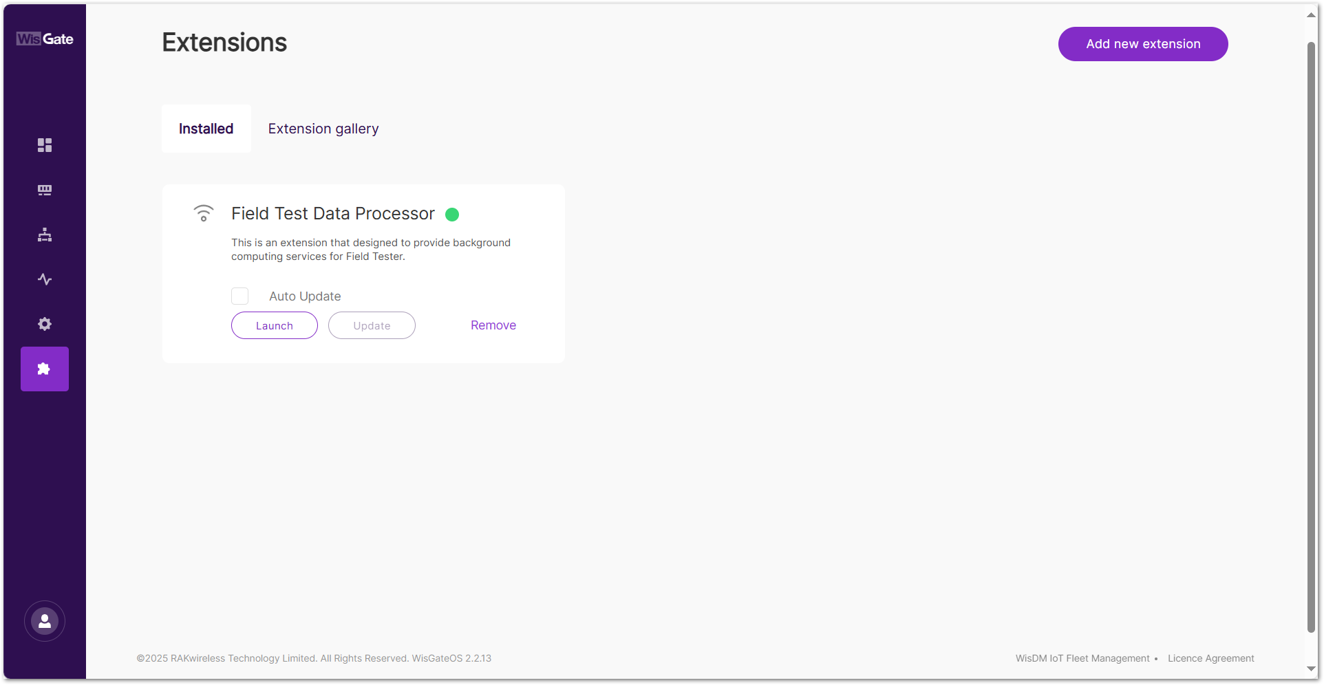 Figure 1: Launch the Field Test Data Processor extension
- Click the Configuration tab to set the following parameters.
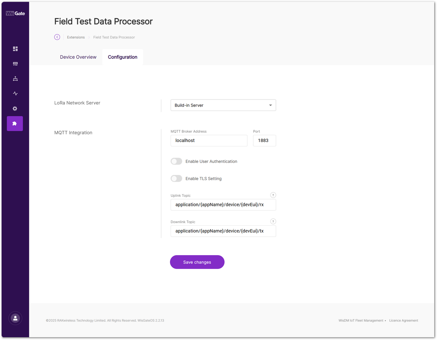 Figure 1: Set parameters
-
LoRa Network Server: Select the LoRaWAN Network Server where the Field Tester device is registered. In this example, select Built-in Server.
-
MQTT Integration:
-
MQTT Broker Address: Set to
localhostfor the built-in server. -
Port: Use the default port
1883. -
Enable User Authentication: Leave as default (no authentication required).
-
Enable TLS Setting: Leave as default.
-
Uplink Topic:
application/{appName}/device/{devEui}/rx -
Downlink Topic:
application/{appName}/device/{devEui}/tx
NOTE{appName}and{devEui}are topic placeholders. Keep them unchanged if you want the extension to process all Field Tester devices under the configured application.- You may replace them with a specific application name or device EUI only when you want to limit processing to a particular application or device. In that case, messages from other applications or devices will not be received or processed by the extension.
-
- To save the changes, click Save changes.
- After the Field Tester successfully joins the network and starts sending uplink data, click the Device Overview tab to view the real-time heatmap and network performance data processed by the Field Test Data Processor Extension.
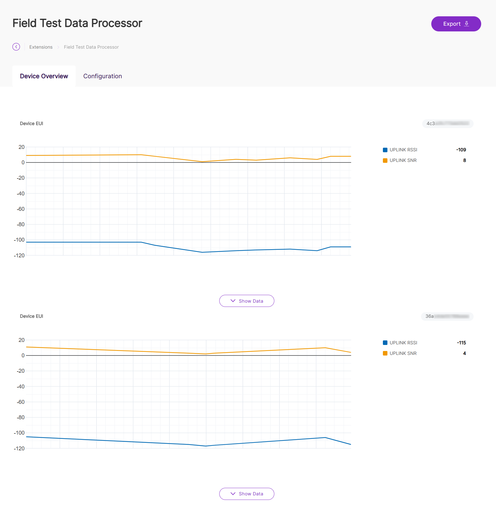 Figure 1: Device Overview
The heatmap is available only when the Field Test Data Processor Extension is correctly connected to the LNS through MQTT and has received valid uplink data from the Field Tester. If no heatmap or performance data appears, verify the device join status, uplink transmission, and MQTT configuration.
- Click Show Data to view a detailed breakdown of all data points collected by the Field Tester. For complete definitions of all parameters shown in this table, refer to the Field Test Data Processor Extension – Parameter Definitions section.
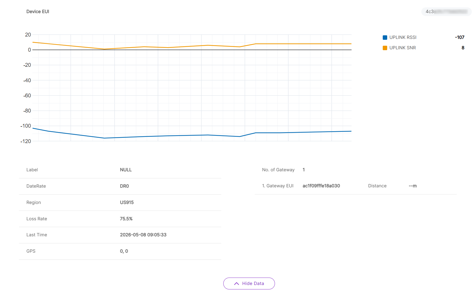 Figure 1: Detailed data
-
(Optional) Click Export to generate a CSV report of the labeled field test data. Export the CSV report when you need to compare signal quality across different test locations, perform further offline analysis, share test results with the project team, or keep the data as part of the project acceptance record.
NOTEOnly data points that have been labeled on the device are included in the exported CSV report.
Chirpstack v3
- To access the Field Test Data Processor extension, click Launch.
Figure 1: Launch the Field Test Data Processor extension- Click the Configuration tab to set the following parameters.
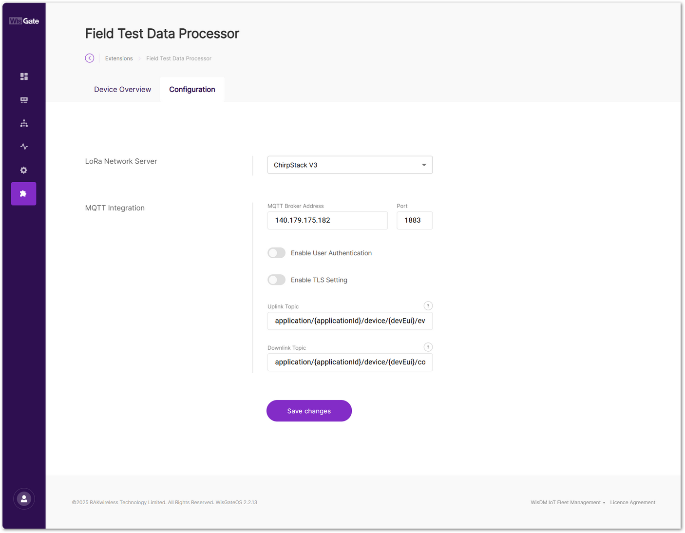 Figure 1: Set parameters
-
LoRa Network Server: Select ChirpStack v3.
-
MQTT Integration:
-
MQTT Broker Address: Enter the IP address or domain of your ChirpStack MQTT broker.
-
Port: Use the default MQTT port
1883. -
Enable User Authentication: Leave as default (no authentication required).
-
Enable TLS Setting: Leave as default.
-
Uplink Topic:
application/{applicationId}/device/{devEui}/event/up -
Downlink Topic:
application/{applicationId}/device/{devEui}/command/down
NOTE{applicationId}and{devEui}are topic placeholders. Keep them unchanged if you want the extension to process all Field Tester devices under the configured application.- You may replace them with a specific application ID or device EUI only when you want to limit processing to a particular application or device. In that case, messages from other applications or devices will not be received or processed by the extension.
-
- To save the changes, click Save changes.
- After the Field Tester successfully joins the network and starts sending uplink data, click the Device Overview tab to view the real-time heatmap and network performance data processed by the Field Test Data Processor Extension.
Figure 1: Device OverviewThe heatmap is available only when the Field Test Data Processor Extension is correctly connected to the LNS through MQTT and has received valid uplink data from the Field Tester. If no heatmap or performance data appears, verify the device join status, uplink transmission, and MQTT configuration.
- Click Show Data to view a detailed breakdown of all data points collected by the Field Tester. For complete definitions of all parameters shown in this table, refer to the Field Test Data Processor Extension – Parameter Definitions section.
Figure 1: Detailed data-
(Optional) Click Export to generate a CSV report of the labeled field test data. Export the CSV report when you need to compare signal quality across different test locations, perform further offline analysis, share test results with the project team, or keep the data as part of the project acceptance record.
NOTEOnly data points that have been labeled on the device are included in the exported CSV report.
Chirpstack v4
- To access the Field Test Data Processor extension, click Launch.
Figure 1: Launch the Field Test Data Processor extension- Click the Configuration tab to set the following parameters.
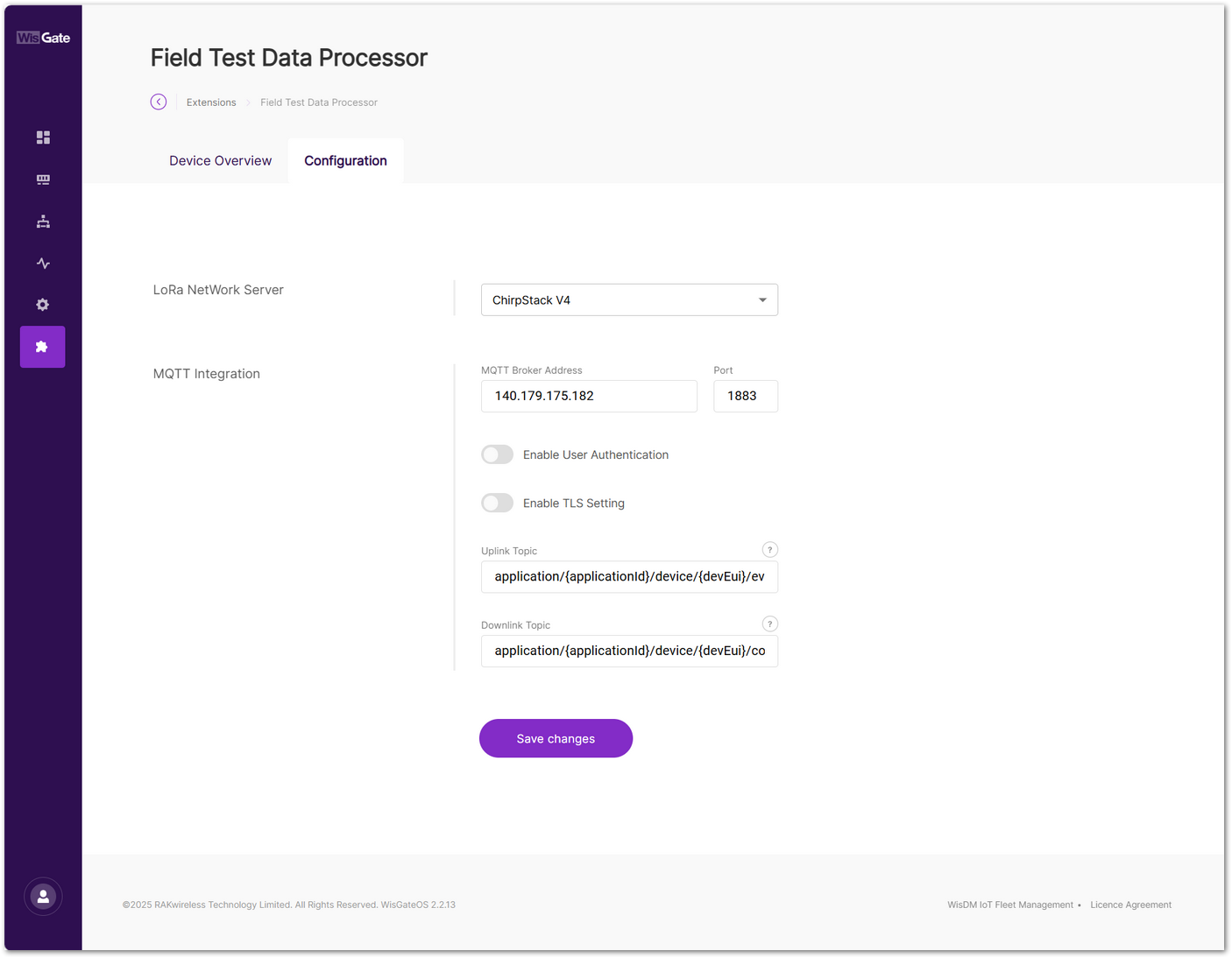 Figure 1: Set parameters
-
LoRa Network Server: Select ChirpStack v4.
-
MQTT Integration:
-
MQTT Broker Address: Enter the IP address or domain of your ChirpStack MQTT broker.
-
Port: Use the default MQTT port
1883. -
Enable User Authentication: Leave as default (no authentication required).
-
Enable TLS Setting: Leave as default.
-
Uplink Topic:
application/{applicationId}/device/{devEui}/event/up -
Downlink Topic:
application/{applicationId}/device/{devEui}/command/down
NOTE{applicationId}and{devEui}are topic placeholders. Keep them unchanged if you want the extension to process all Field Tester devices under the configured application.- You may replace them with a specific application ID or device EUI only when you want to limit processing to a particular application or device. In that case, messages from other applications or devices will not be received or processed by the extension.
-
- To save the changes, click Save changes.
- After the Field Tester successfully joins the network and starts sending uplink data, click the Device Overview tab to view the real-time heatmap and network performance data processed by the Field Test Data Processor Extension.
Figure 1: Device OverviewThe heatmap is available only when the Field Test Data Processor Extension is correctly connected to the LNS through MQTT and has received valid uplink data from the Field Tester. If no heatmap or performance data appears, verify the device join status, uplink transmission, and MQTT configuration.
- Click Show Data to view a detailed breakdown of all data points collected by the Field Tester. For complete definitions of all parameters shown in this table, refer to the Field Test Data Processor Extension – Parameter Definitions section.
Figure 1: Detailed data-
(Optional) Click Export to generate a CSV report of the labeled field test data. Export the CSV report when you need to compare signal quality across different test locations, perform further offline analysis, share test results with the project team, or keep the data as part of the project acceptance record.
NOTEOnly data points that have been labeled on the device are included in the exported CSV report.
The Things Network
- To access the Field Test Data Processor extension, click Launch.
Figure 1: Launch the Field Test Data Processor extension- Click the Configuration tab to set the following parameters.
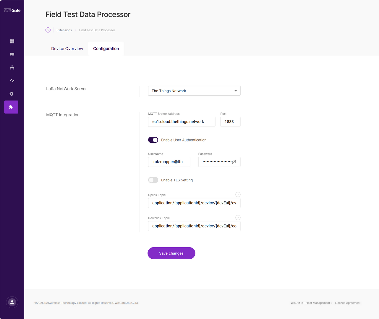 Figure 1: Set parameters
On TTN, you can view your application's MQTT credentials under: Applications > your application > Other integrations > MQTT.
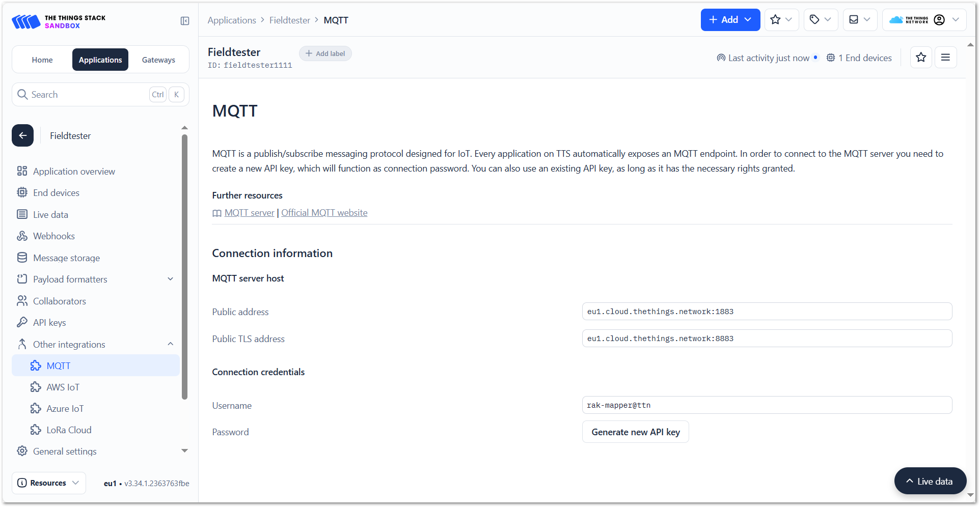 Figure 1: MQTT integration credentials
-
LoRa Network Server: Select the LoRaWAN server where your Field Tester device is registered. In this case, choose The Things Network.
-
MQTT Integration:
-
MQTT Broker Address: The public address for the MQTT broker is
eu1.cloud.thethings.network. -
Port: Use the default MQTT port:
1883 -
Enable User Authentication: This option must be enabled.
- Username: Copy the Username from the MQTT Connection credentials section in the TTN console.
- Password: Use the API key generated by clicking Generate new API key in the TTN console.
-
Enable TLS Setting: Leave this at its default value.
-
Uplink Topic: Uplink topic template:
application/{applicationId}/device/{devEui}/event/up -
Downlink Topic: Downlink topic template:
application/{applicationId}/device/{devEui}/command/up
NOTE{applicationId}and{devEui}are topic placeholders. Keep them unchanged if you want the extension to process all Field Tester devices under the configured application.- You may replace them with a specific application ID or device EUI only when you want to limit processing to a particular application or device. In that case, messages from other applications or devices will not be received or processed by the extension.
-
- To save the changes, click Save changes.
- After the Field Tester successfully joins the network and starts sending uplink data, click the Device Overview tab to view the real-time heatmap and network performance data processed by the Field Test Data Processor Extension.
Figure 1: Device OverviewThe heatmap is available only when the Field Test Data Processor Extension is correctly connected to the LNS through MQTT and has received valid uplink data from the Field Tester. If no heatmap or performance data appears, verify the device join status, uplink transmission, and MQTT configuration.
- Click Show Data to view a detailed breakdown of all data points collected by the Field Tester. For complete definitions of all parameters shown in this table, refer to the Field Test Data Processor Extension – Parameter Definitions section.
Figure 1: Detailed data-
(Optional) Click Export to generate a CSV report of the labeled field test data. Export the CSV report when you need to compare signal quality across different test locations, perform further offline analysis, share test results with the project team, or keep the data as part of the project acceptance record.
NOTEOnly data points that have been labeled on the device are included in the exported CSV report.
AWS IoT
- To access the Field Test Data Processor extension, click Launch.
Figure 1: Launch the Field Test Data Processor extension- Click the Configuration tab to set the following parameters.
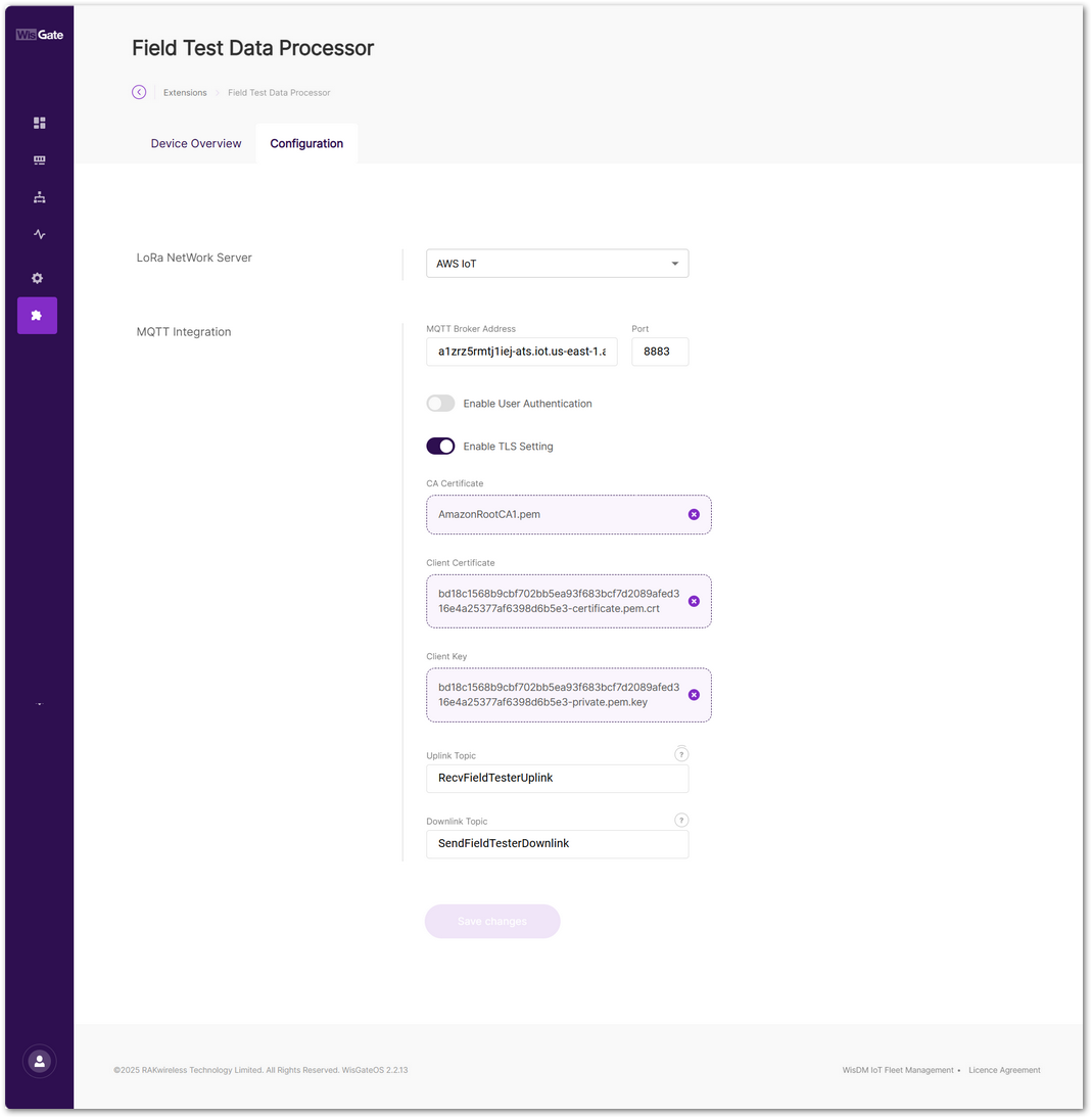 Figure 1: Configure the MQTT broker parameters
-
LoRa NetWork Server: Select AWS IoT.
-
MQTT Broker Address:
To obtain the MQTT broker address, navigate to: AWS IoT > Connect > Domain configurations, then click on iot:Data-ATS in the Domain configurations list and copy the Domain name.
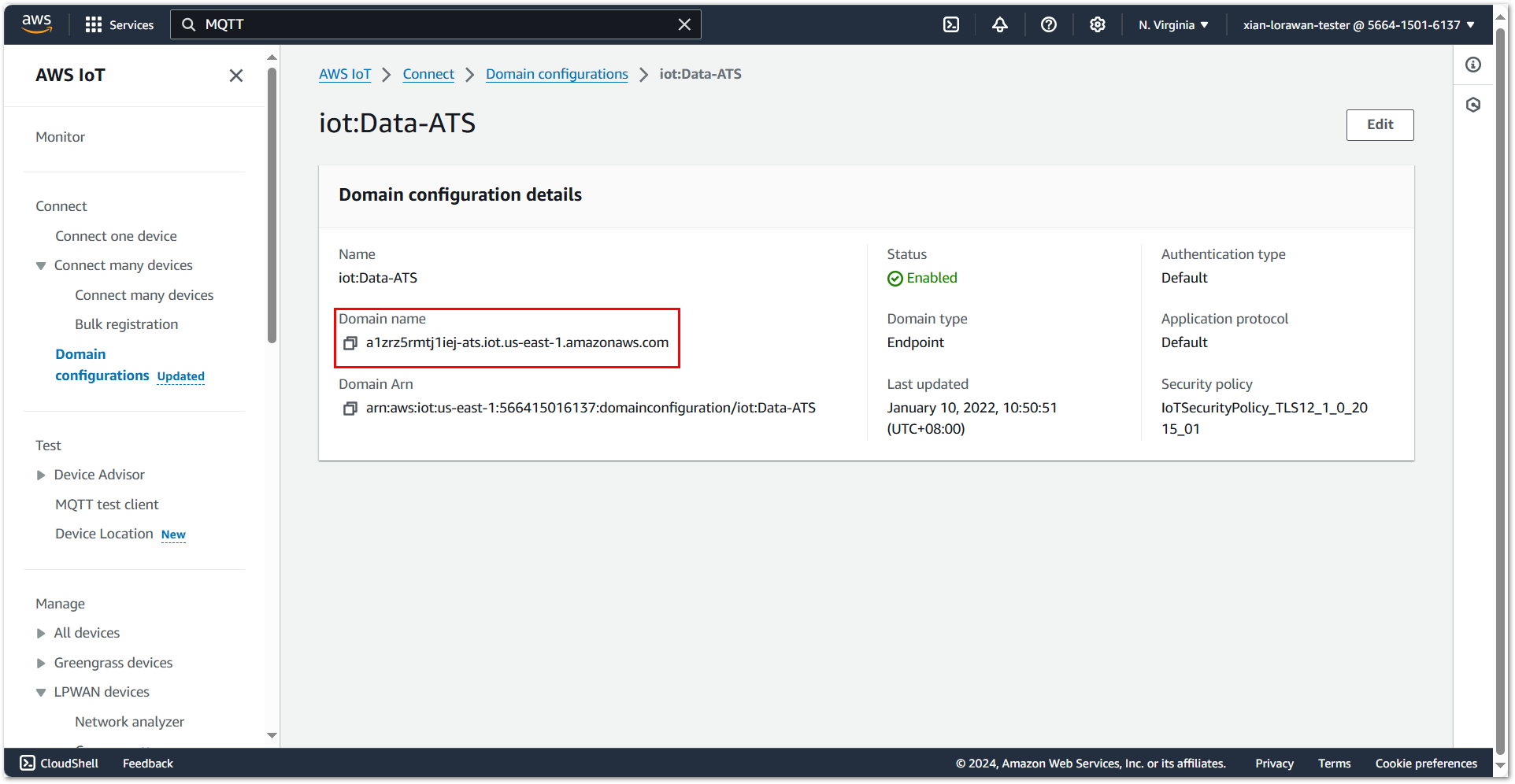 Figure 1: Configure the MQTT broker address
 -
Port: Set to
8883, the default port for secure MQTT communication over TLS. -
Enable User Authentication: Leave this setting as default.
-
Enable TLS Setting: Enable TLS setting to ensure the security of MQTT message transmissions. Therefore, you need to create certificates in AWS IoT.
a. AWS IoT policies allow you to control access to the AWS IoT Core data plane operations. To create an AWS IoT policy. Go to AWS IoT > Security > Policies, click Create policy.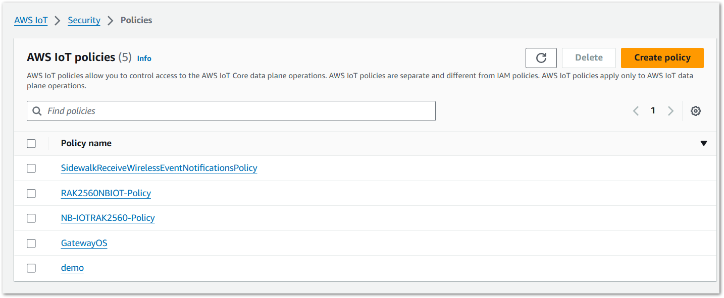 Figure 1: Go to create an AWS IoT policy
b. Configure policy parameters and click Create.
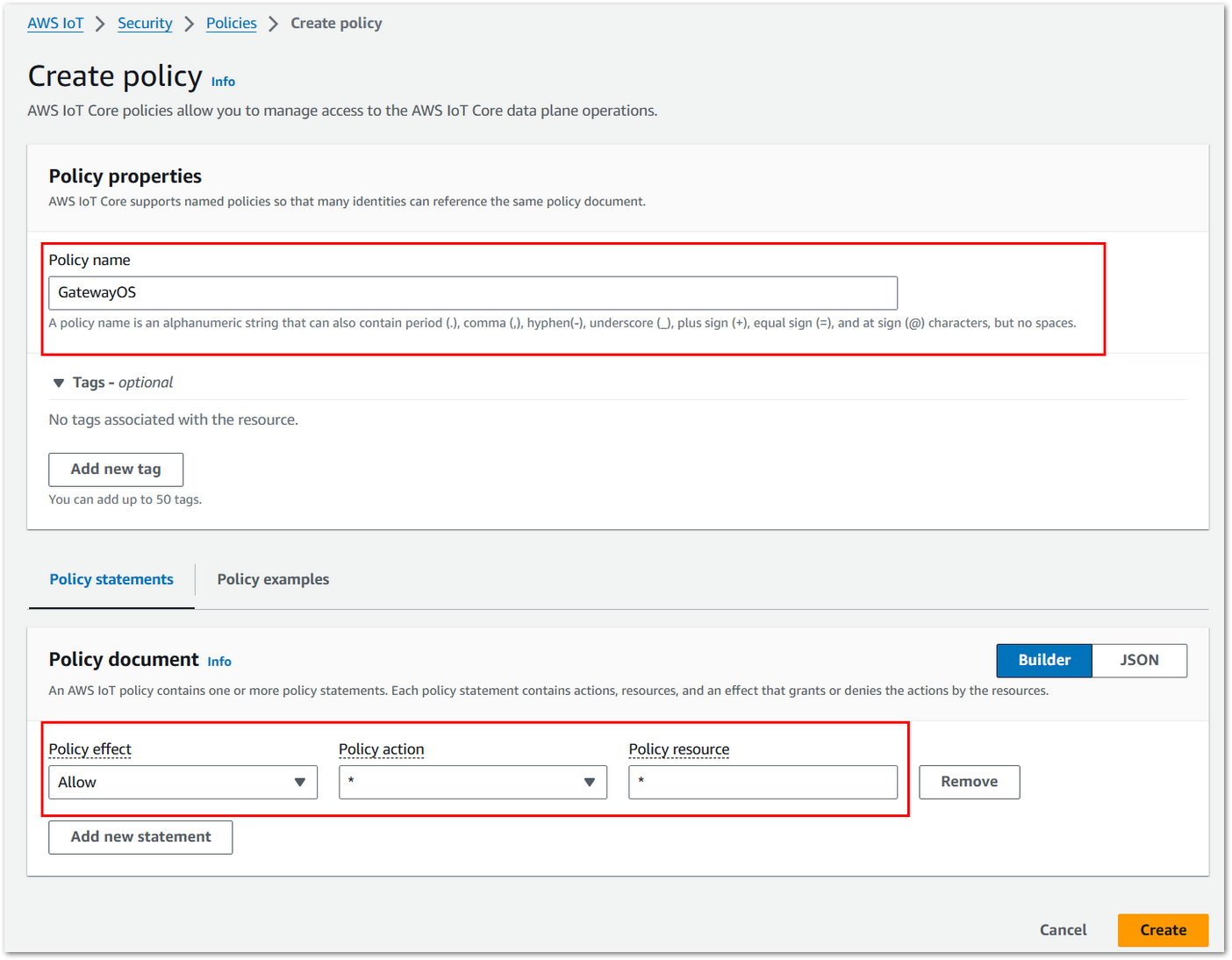 Figure 1: Configure parameters
c. Create certificates to authenticate the connection between the device and the Field Test Data Processor extension. Go to AWS IoT > Security > Certificates, click Create certificate.
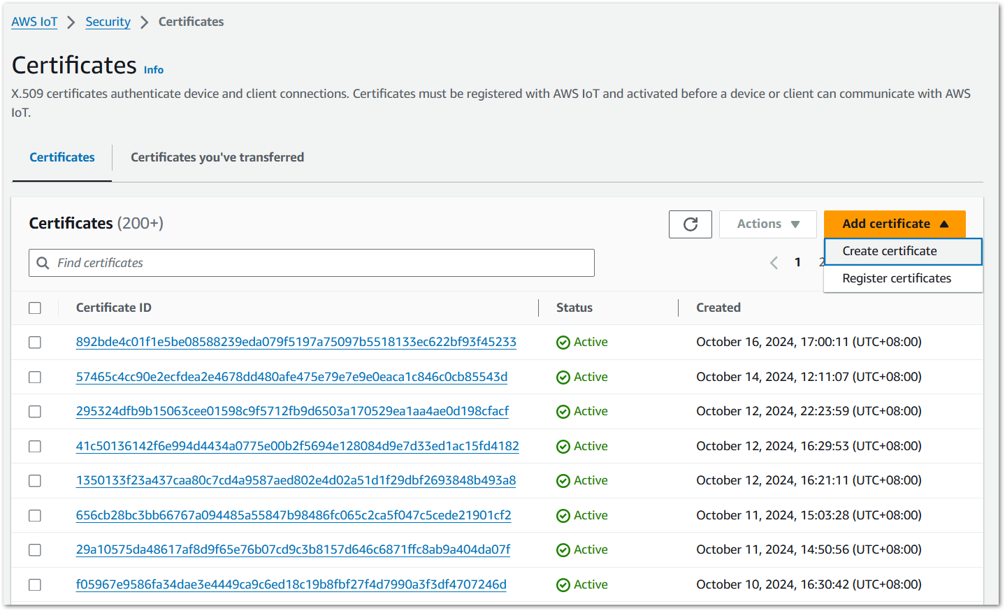 Figure 1: Go to create certificates
d. Configure certificate parameters and click Create.
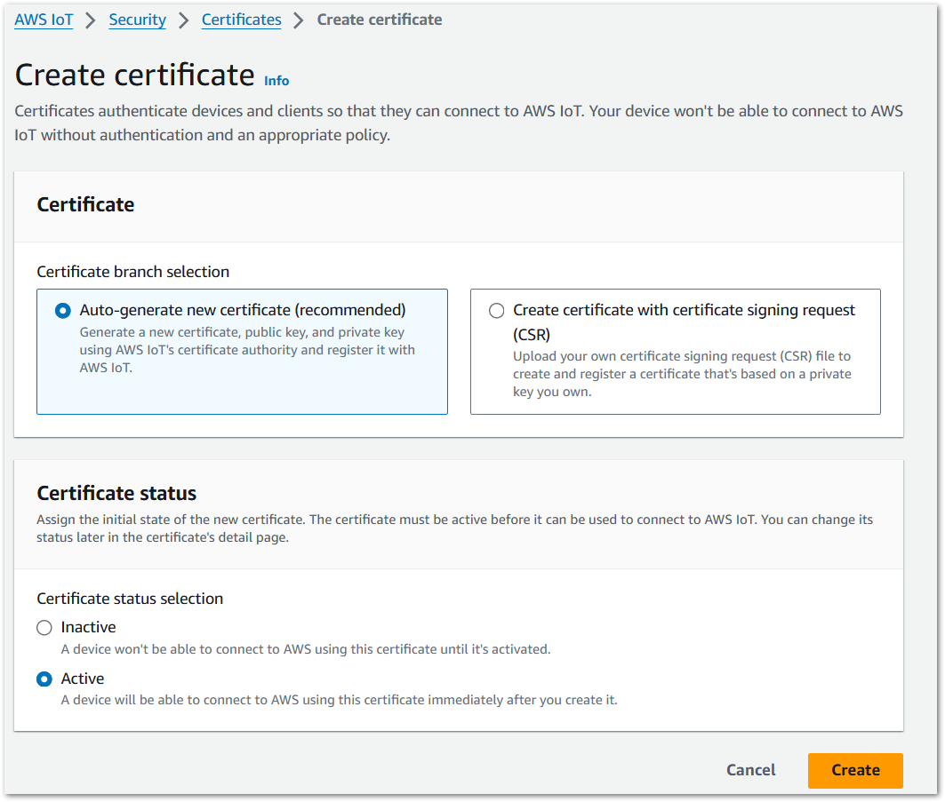 Figure 1: Configure parameters
e. Download the certificate and key files. Click Continue.
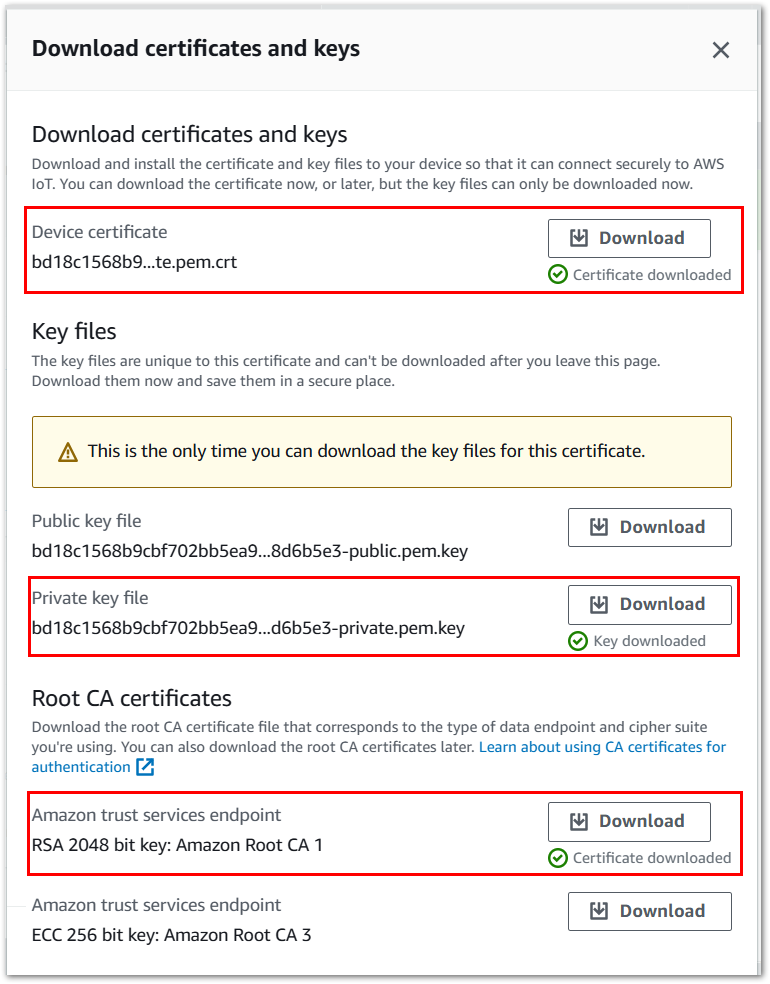 Figure 1: Download the certificate and key files
f. In the Certificates list, click the Certificate ID created in the previous step to enter the certificate details page.
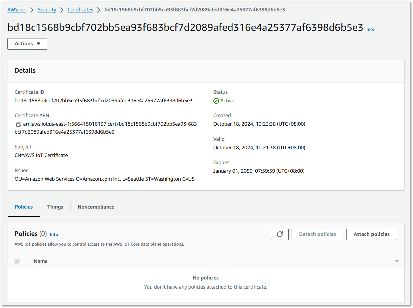 Figure 1: Certificate details
g. Click Attach policies to add the created AWS IoT policy for the certificates.
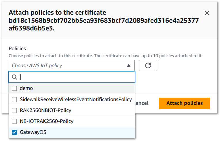 Figure 1: Attach policies
h. Add the certificates to the Field Test Data Processor extension.
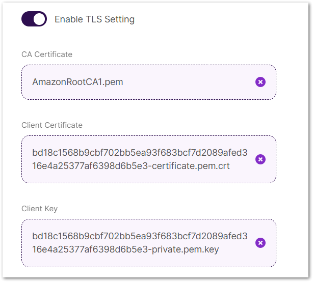 Figure 1: Add certificates
 -
Uplink Topic: To receive the uplink data from AWS IoT, you need to create a destination that will process the uplink data to this uplink topic.
The uplink topic used here should match the one configured in your AWS IoT destination (e.g.,
RecvFieldTesterUplink), which is typically created during device registration. -
Downlink Topic: To send downlink messages to a Field Tester device, you need to create a Lambda function.
a. To create a Lambda function. Go to the AWS Lambda console and click Create function.
b. Configure the function name and runtime. Figure 1: Create Lambda function
c. Copy the following Python code into the Code source and click Deploy.
import json
import boto3
import base64
import codecs
import binascii
client = boto3.client("iotwireless")
def lambda_handler(event, context):
print(event)
device_id = event["deviceID"]
data = event["data"]
fPort = event["fPort"]
client.send_data_to_wireless_device(TransmitMode=0,
Id=device_id,
WirelessMetadata={
"LoRaWAN": {"FPort": fPort}},
PayloadData=data)
return {
'statusCode': 200,
'body': json.dumps('Hello from Lambda!')
}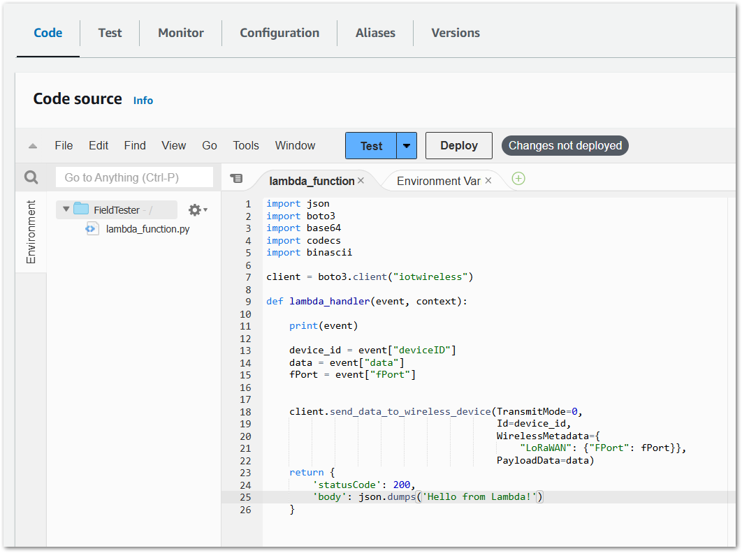 Figure 1: Add Python code
d. Create a message routing rule in AWS IoT to subscribe the downlink topic and call this Lambda Function to process the downlink message. Go to AWS IoT > Message routing > Rules and click Create rule.
e. Follow the steps in the following figure to create the message routing rule. Then click Create.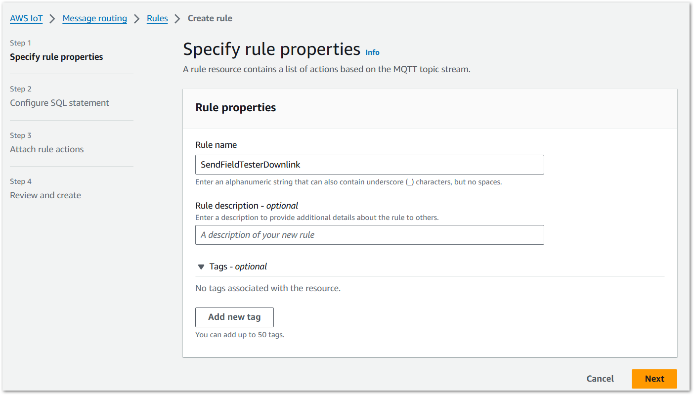 Figure 1: Specify rule properties
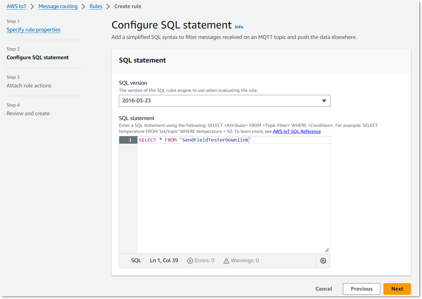 Figure 1: Configure SQL statement
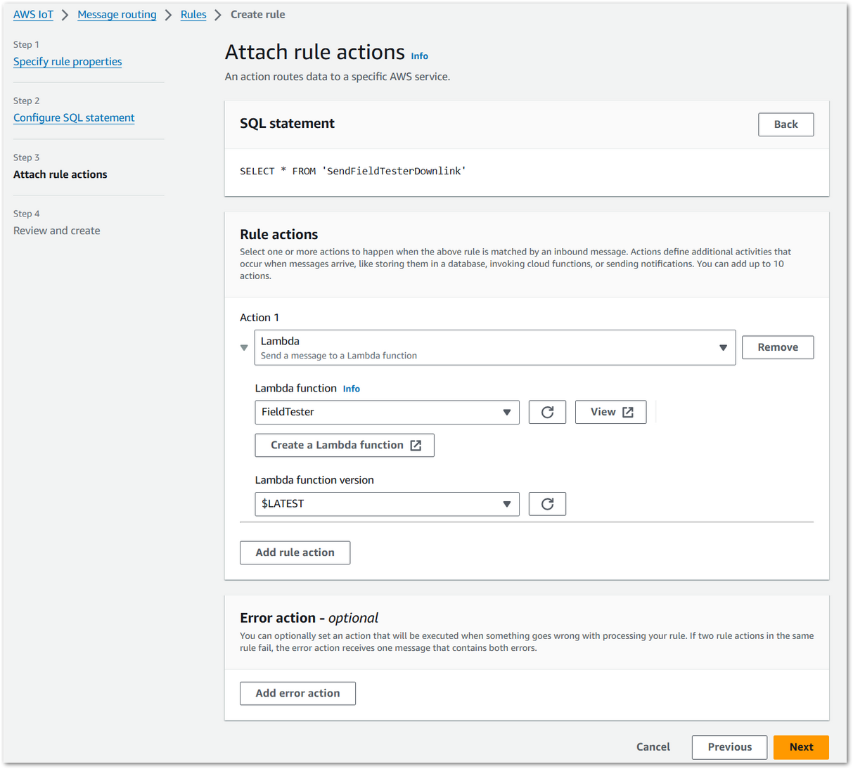 Figure 1: Attach rule actions
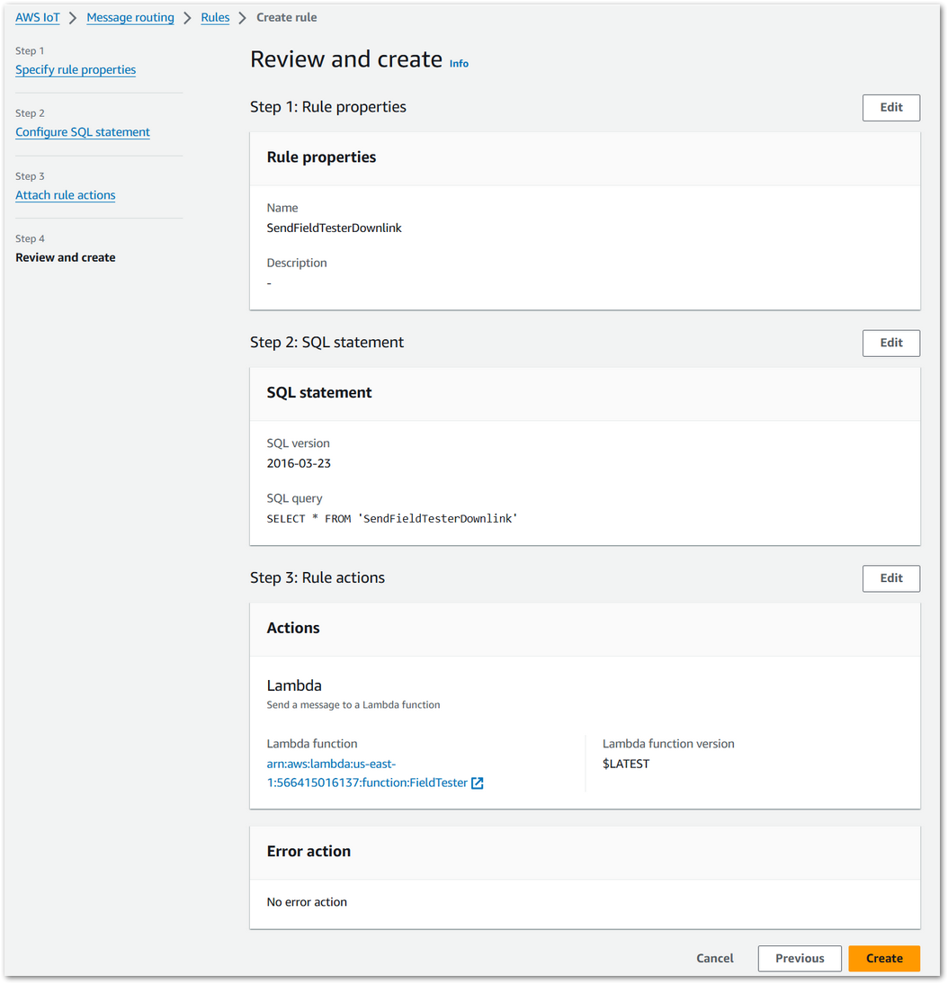 Figure 1: Review and create
f. Configure the downlink topic.
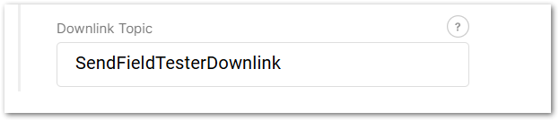 Figure 1: Downlink topic
- To save the changes, click Save changes.
- After the Field Tester successfully joins the network and starts sending uplink data, click the Device Overview tab to view the real-time heatmap and network performance data processed by the Field Test Data Processor Extension.
Figure 1: Device OverviewThe heatmap is available only when the Field Test Data Processor Extension is correctly connected to the LNS through MQTT and has received valid uplink data from the Field Tester. If no heatmap or performance data appears, verify the device join status, uplink transmission, and MQTT configuration.
- Click Show Data to view a detailed breakdown of all data points collected by the Field Tester. For complete definitions of all parameters shown in this table, refer to the Field Test Data Processor Extension – Parameter Definitions section.
Figure 1: Detailed data-
(Optional) Click Export to generate a CSV report of the labeled field test data. Export the CSV report when you need to compare signal quality across different test locations, perform further offline analysis, share test results with the project team, or keep the data as part of the project acceptance record.
NOTEOnly data points that have been labeled on the device are included in the exported CSV report.
The Things Industries
- To access the Field Test Data Processor extension, click Launch.
Figure 1: Launch the Field Test Data Processor extension- Click the Configuration tab to set the following parameters.
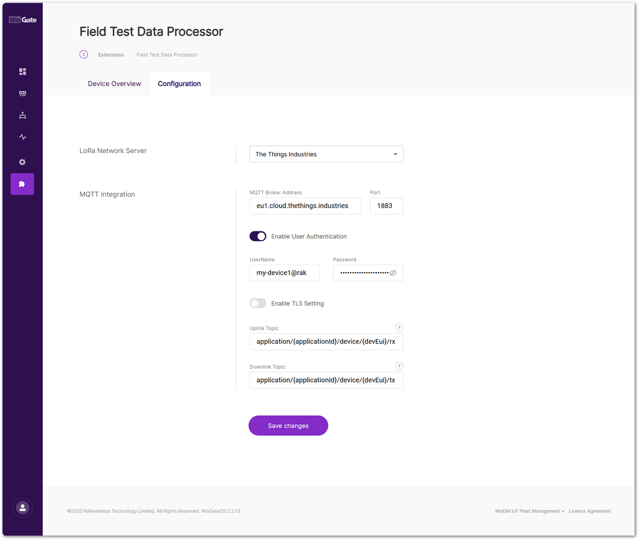 Figure 1: Set parameters
On TTI, you can view your application's MQTT credentials under: Applications > your application > Other integrations > MQTT.
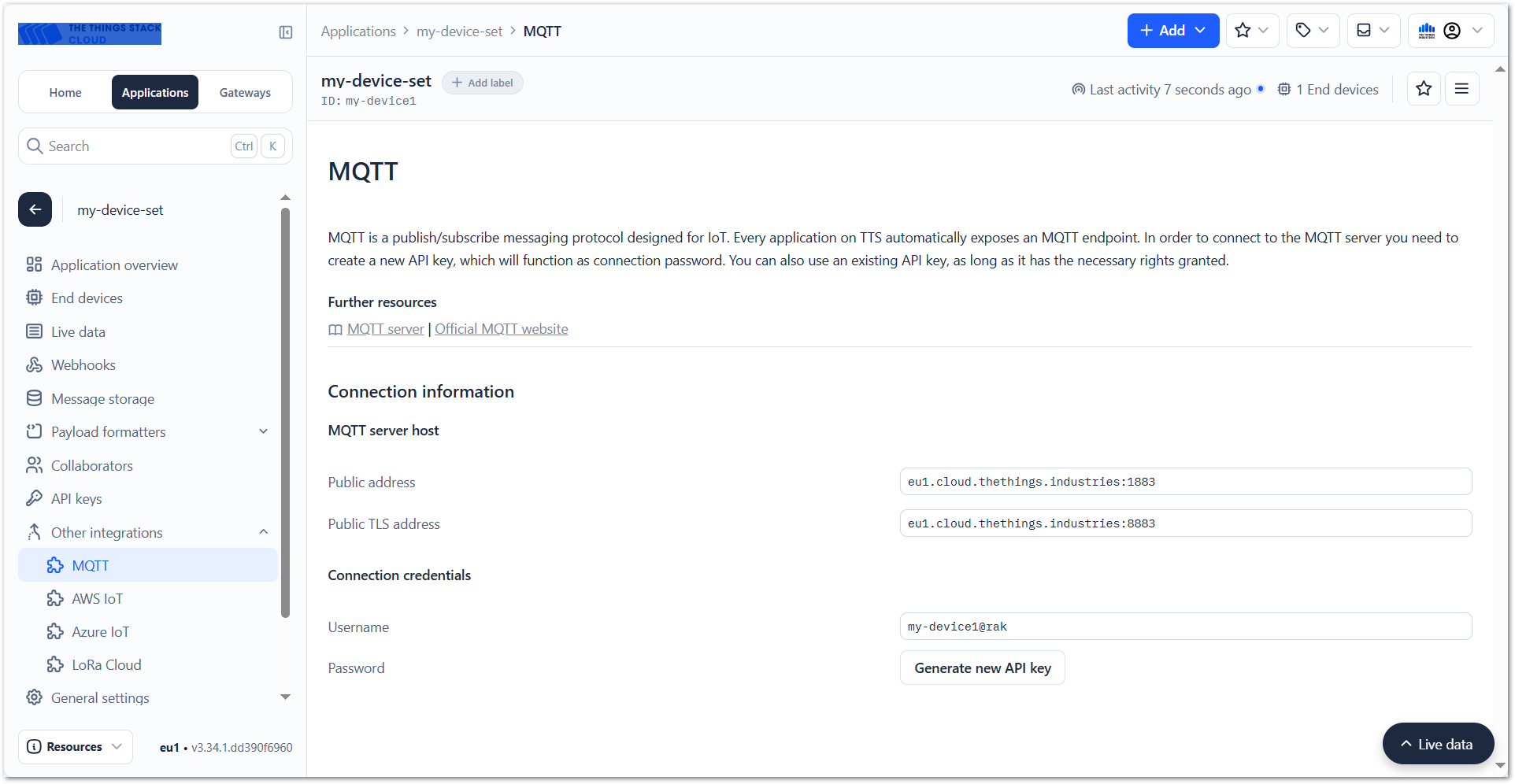 Figure 1: MQTT integration
-
LoRa Network Server: Select The Things Industries.
-
MQTT Integration:
-
MQTT Broker Address: Use the TTI public MQTT broker address:
eu1.cloud.thethings.industries -
Port: The default MQTT port is
1883. -
Enable User Authentication: This option must be enabled.
- Username: Copy the Username from the MQTT Connection credentials section in the TTN console.
- Password: Use the API key generated by clicking Generate new API key in the TTN console.
-
Enable TLS Setting: Leave this at its default value.
-
Uplink Topic:
application/{applicationId}/device/{devEui}/event/up -
Downlink Topic:
application/{applicationId}/device/{devEui}/command/down
NOTE{applicationId}and{devEui}are topic placeholders. Keep them unchanged if you want the extension to process all Field Tester devices under the configured application.- You may replace them with a specific application ID or device EUI only when you want to limit processing to a particular application or device. In that case, messages from other applications or devices will not be received or processed by the extension.
-
- To save the changes, click Save changes.
- After the Field Tester successfully joins the network and starts sending uplink data, click the Device Overview tab to view the real-time heatmap and network performance data processed by the Field Test Data Processor Extension.
Figure 1: Device OverviewThe heatmap is available only when the Field Test Data Processor Extension is correctly connected to the LNS through MQTT and has received valid uplink data from the Field Tester. If no heatmap or performance data appears, verify the device join status, uplink transmission, and MQTT configuration.
- Click Show Data to view a detailed breakdown of all data points collected by the Field Tester. For complete definitions of all parameters shown in this table, refer to the Field Test Data Processor Extension – Parameter Definitions section.
Figure 1: Detailed data-
(Optional) Click Export to generate a CSV report of the labeled field test data. Export the CSV report when you need to compare signal quality across different test locations, perform further offline analysis, share test results with the project team, or keep the data as part of the project acceptance record.
NOTEOnly data points that have been labeled on the device are included in the exported CSV report.
Failover Reboot
The Failover Reboot tool periodically checks the status of all enabled network links (LTE / Ethernet / Wi-Fi) of the gateway. Once it detects that all network links are offline, it will try to restore network connectivity by rebooting LTE module or gateway with failover.
The following is the logic diagram of the Failover Reboot extension.
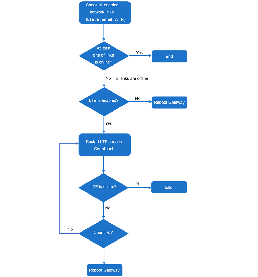 Figure 1: Logic diagram
- This extension is only compatible with WisGateOS 2 2.2.x and later.
- The gateway can be rebooted up to five times.
Install the Failover Reboot Extension
To install the extension, follow the steps in How to Add an Extension section.
Configure the Failover Reboot Extension
- To access the Failover Reboot extension, click Launch.
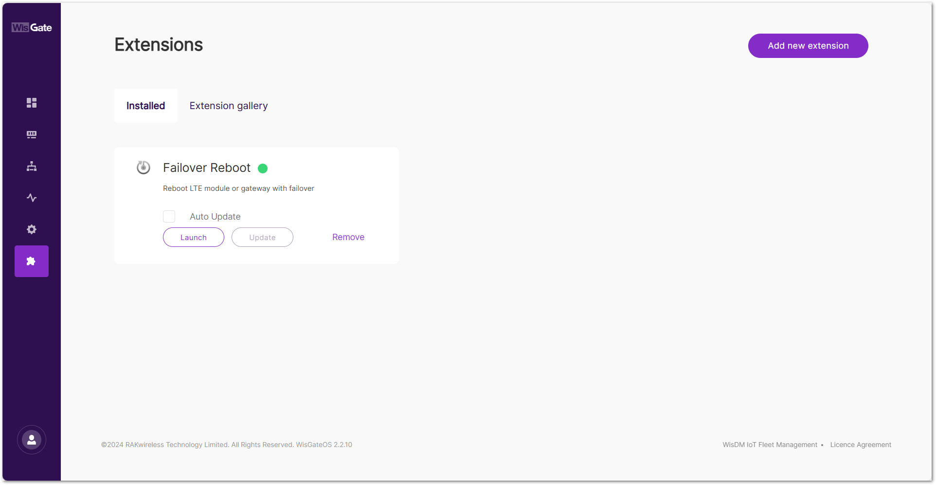 Figure 1: Extensions tab
- In the configuration page, enable the Failover Reboot service and set the Check Interval.
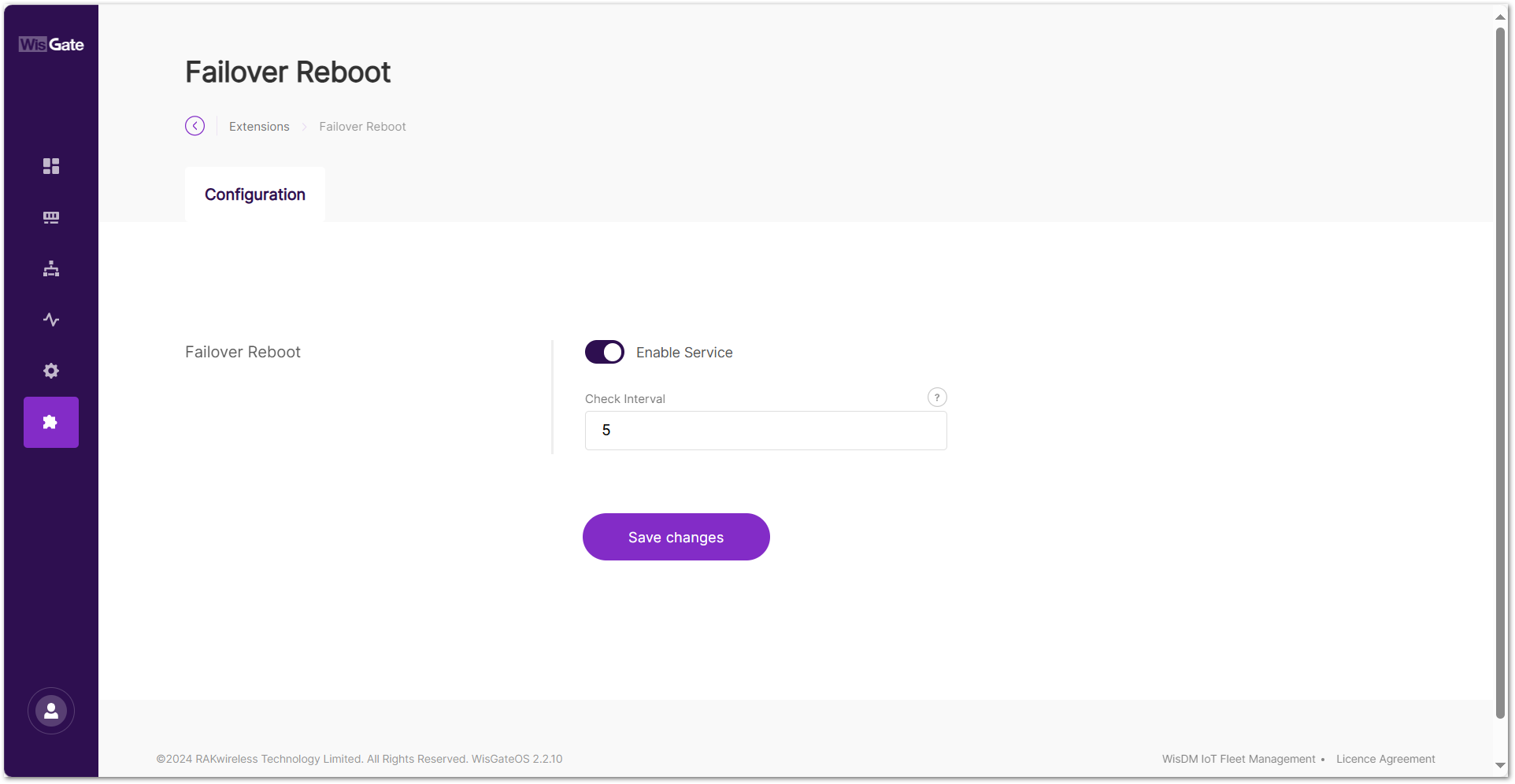 Figure 1: Configuration page
-
Enable Service: the Failover Reboot service
-
Check Interval: time interval for checking the network status, in minutes
- To save the changes, click Save changes.
Wi-Fi Reboot
This extension monitors Wi-Fi connectivity by periodically sending ping and httping requests to specified targets. If all tests consistently fail, it will trigger a Wi-Fi module reboot, and escalate to a full system reboot if necessary. This extension is only compatible with WisGateOS 2 2.2.x and later.
Link Check Logic
- Scheduled Connectivity Tests
- Performs ping tests to all user-defined IP targets at regular intervals.
- If all ping targets fail, the system proceeds to the next step.
- Fallback HTTPing
- Sends HTTP requests to all configured web URLs.
- If all HTTPing targets also fail, the system records a failure count and begins recovery.
- Recovery Mechanism
- Step 1: Reboots the Wi-Fi module to attempt recovery.
- Step 2: If failures continue after rebooting the module, the extension will reboot the entire gateway.
If the gateway remains reachable through a backup connection (e.g., Ethernet or Cellular), and any ping or httping test succeeds through that path, no recovery action will be triggered, even if the Wi-Fi interface is down.
Install the Wi-Fi Reboot Extension
To install the extension, follow the steps in How to Add an Extension section.
Configure the Wi-Fi Reboot Extension
- To access the Wi-Fi Reboot extension, click Launch.
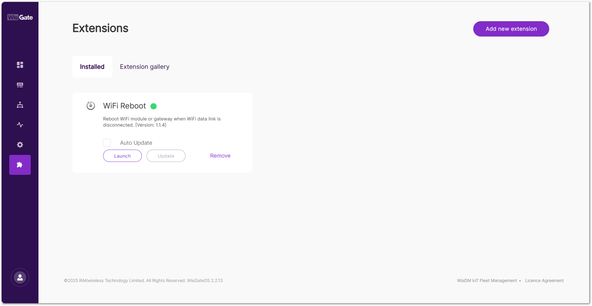 Figure 1: Extensions tab
- On the configuration page, configure the following parameters.
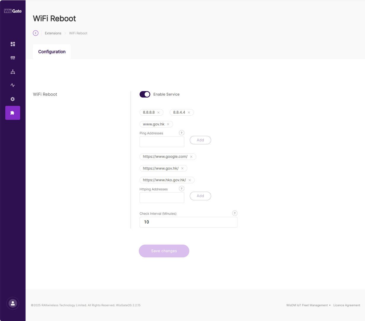 Figure 1: Configuration page
| Field | Description |
|---|---|
| Enable Service | Toggle to enable or disable the WiFi Reboot extension. Enabled by default. |
| Ping Addresses | Define one or more IP addresses or domain names to be used for ICMP ping tests. These addresses help determine whether the gateway can reach the outside network. Examples: 8.8.8.8 (Google DNS)8.8.4.4 (Google DNS Backup)www.gov.hk (HK Government)Can be public or private IPs. ⚠️ WARNING Avoid incorrect or unreachable entries to prevent false positives and unnecessary reboots. |
| Httping Addresses | Define one or more full URLs (must include http:// or https://) for HTTP-based service availability testing.Examples: https://www.google.com/https://www.gov.hk/https://www.hko.gov.hk/URLs can point to internal status pages or public web services. ⚠️ WARNING Only HTTP/HTTPS is supported (no FTP, RTSP). Pages must return status code 200 to be considered successful. |
| Check Interval (Minutes) | Determines how often the extension checks Wi-Fi connectivity. Recommended value: 10 minutes by default. |
- To save the changes, click Save changes.
RF Spectrum Scanner
The RF Spectrum Scanner extension allows you to scan and visualize RF spectrum activity in real time across a defined frequency range. Using color-coded heatmaps that map signal strength (RSSI) over time and frequency, it helps you detect interference, identify noisy channels, and understand how the spectrum environment behaves.
This tool is especially useful for:
- Analyzing RF noise and potential interference in real-world deployments
- Identifying the best frequency sub-bands for reliable LoRa communication
- Troubleshooting poor network performance due to channel congestion
- Running regular audits of the local RF environment
All completed scans are saved automatically and can be reviewed or exported from the History tab for further analysis or record keeping.
-
Starting a spectrum scan will temporarily stop all LoRaWAN transmissions. Make sure it won't disrupt any critical services before you continue.
-
Currently supported only on RAK7289V2 gateways due to hardware requirements.
Install the RF Spectrum Scanner Extension
To install the extension, follow the steps in How to Add an Extension section.
Configure the RF Spectrum Scanner Extension
- To access the RF Spectrum Scanner extension, click Launch.
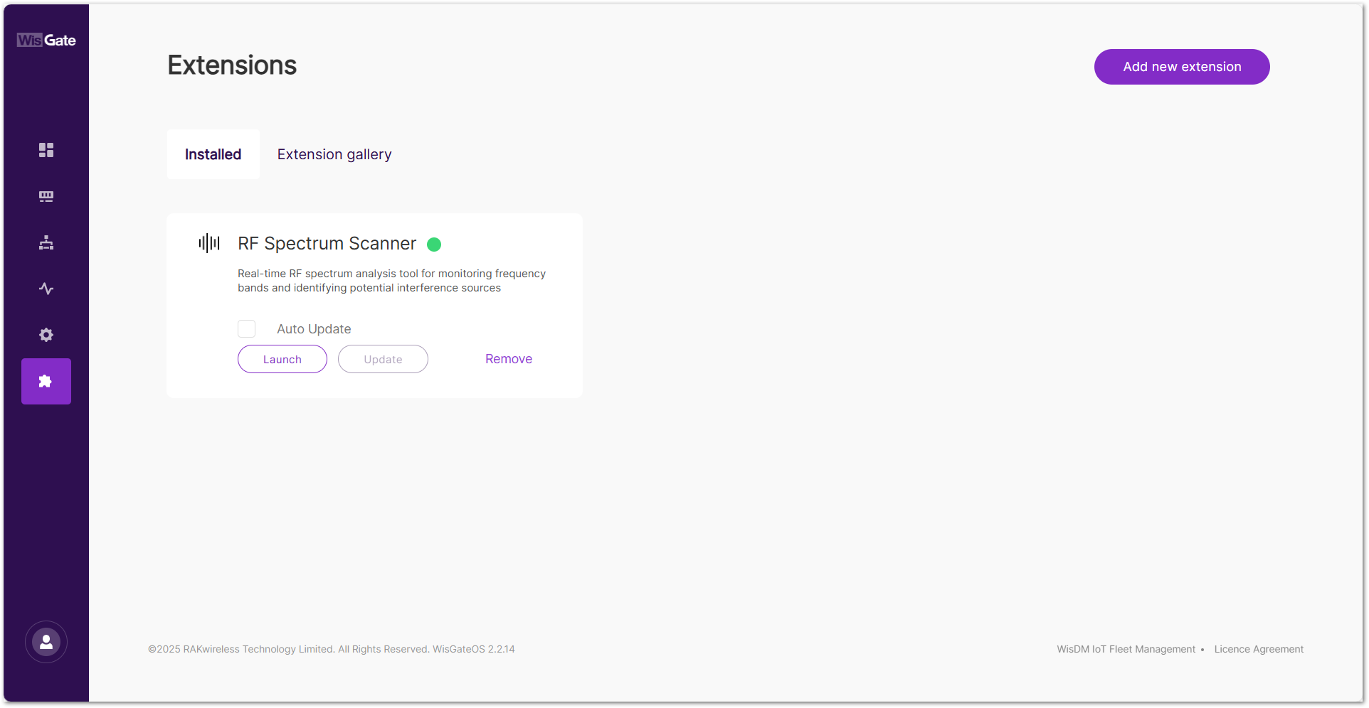 Figure 1: Extensions tab
- In the Live Scan tab, configure the following scan parameters:
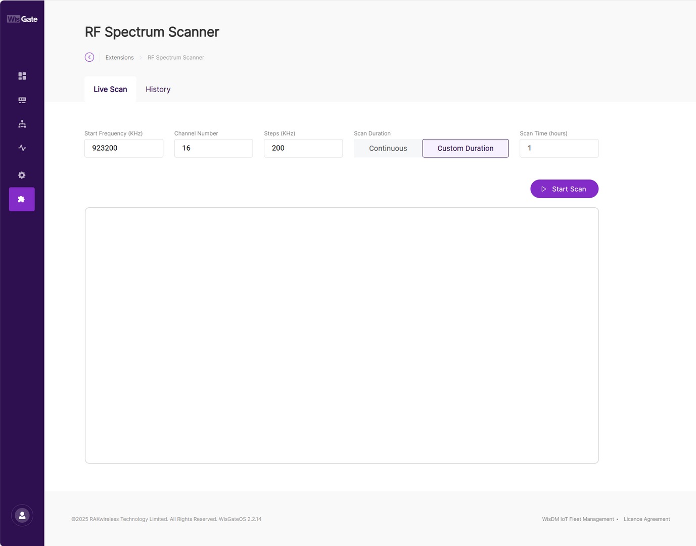 Figure 1: Configuration parameters
| Field | Description | Valid Range / Notes |
|---|---|---|
| Start Frequency (KHz) | Starting frequency of the scan range | 863000~925000 kHz (must be within gateway RF band) |
| Channel Number | Total number of frequency points (channels) to scan | Must be an integer ≥1 and ≤32 |
| Steps (KHz) | Frequency increment between each channel | 10~500 kHz |
| Scan Duration | Determines how long the scan runs |
|
| Scan Time (hours) | Duration of scan if Custom Duration is selected | Integer from 1 to 168 |
- Click Start Scan to initiate the scan.
- A confirmation dialog will appear. Click Confirm to proceed.
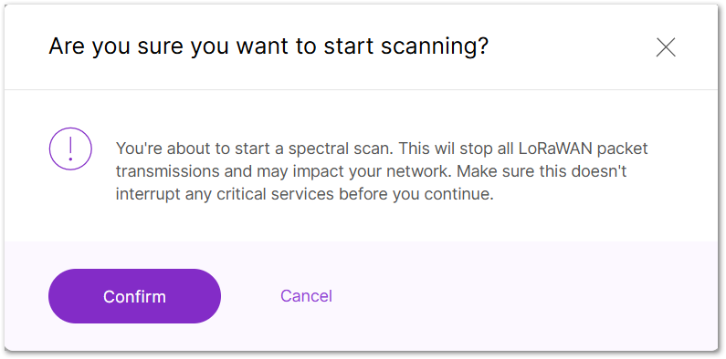 Figure 1: Confirm to start scanning
- Once scanning begins, a real-time chart appears showing signal strength across the scanned frequency range:
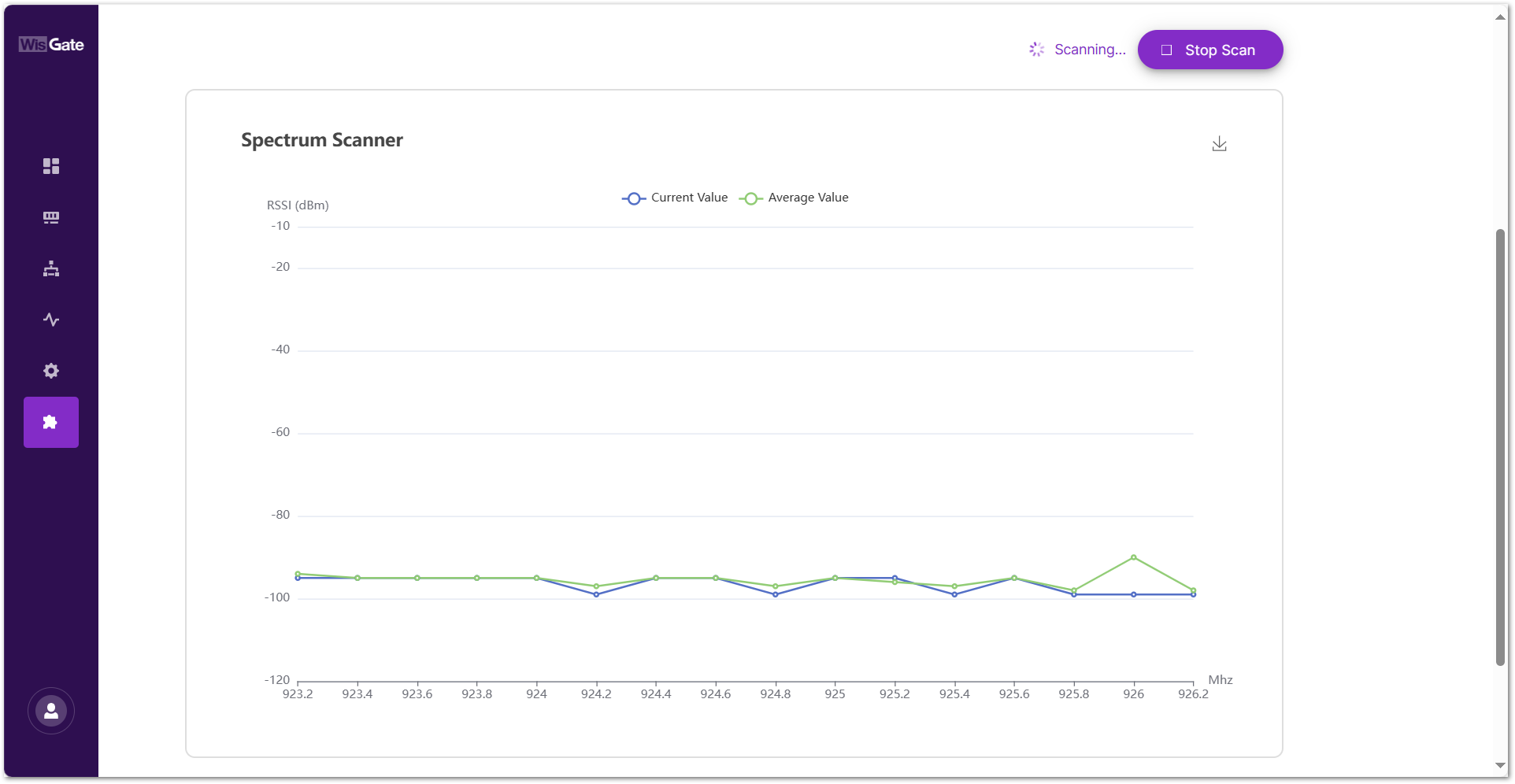 Figure 1: Scanning
- X-Axis (MHz): Shows the frequency range being scanned.
- Y-Axis (RSSI in dBm): Displays signal strength levels for each frequency point.
- Current Value (Blue Line): Live RSSI readings captured during the current scan cycle.
- Average Value (Green Line): Running average of RSSI values since the scan started.
- Download Icon: Click to save the current chart as a PNG image.
- Stop Scan: Click to end the ongoing scan.
Viewing and Managing Scan History
All completed spectrum scans are automatically saved and accessible from the History tab. This section allows users to review past scans, visualize average signal levels, and export scan data for further analysis or archiving.
Each row in the History table represents a scan session. The following details are shown for each session:
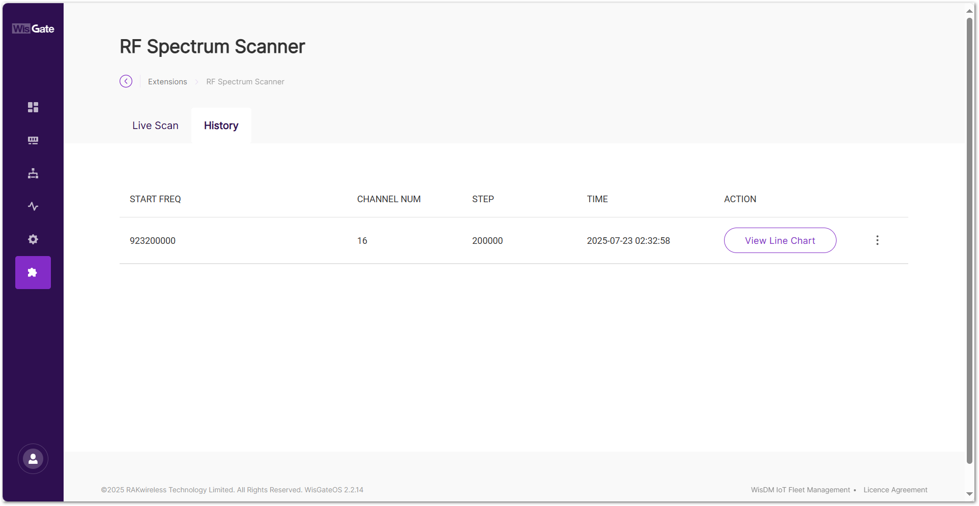 Figure 1: Scan records
-
START FREQ: The starting frequency of the scan (in Hz).
-
CHANNEL NUM: The number of scanned frequency channels.
-
STEP: The step size between each frequency (in Hz).
-
TIME: The timestamp when the scan was initiated.
-
ACTION:
-
View Line Chart: Click View Line Chart to display a graphical summary of the selected scan.
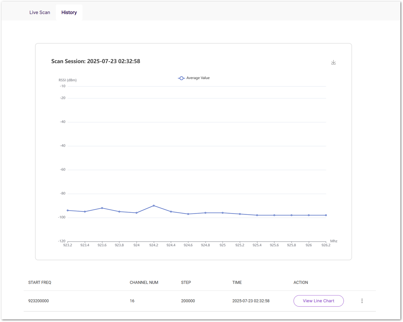 Figure 1: Scan session
 -
Export as Data: Click ⋮ menu and select Export as Data will download the raw scan results as a CSV file.
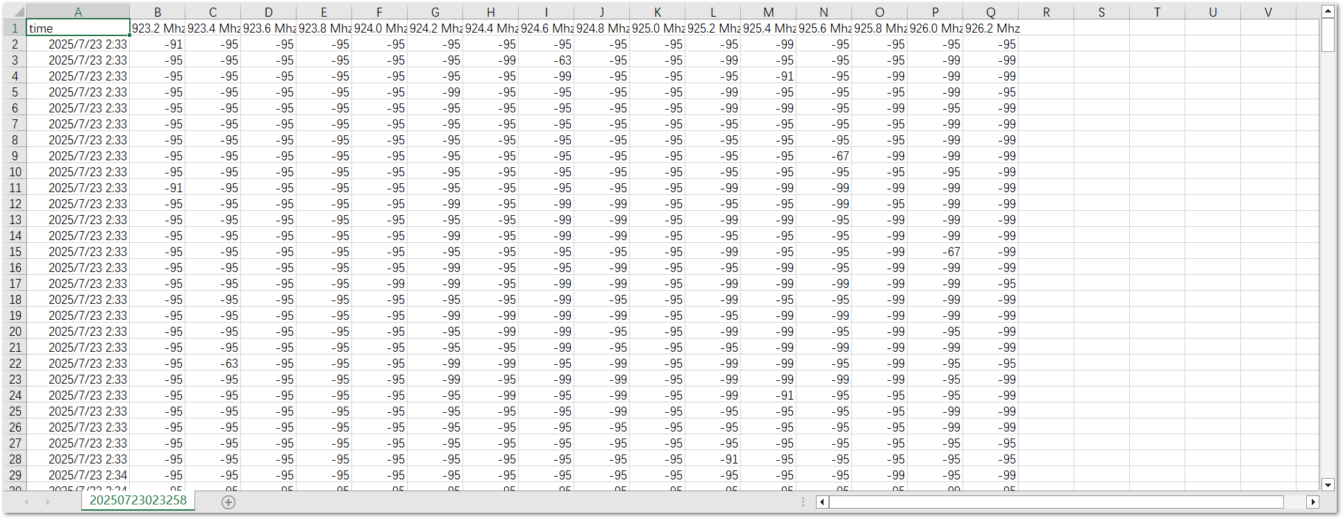 Figure 1: Downloaded data
 -
Delete: Removes the scan record from the list.
-
LoRa® Packet Logger
The LoRa® Packet Logger extension records and manages all uplink and downlink LoRa packets with configurable retention periods and health monitoring. It provides a reliable local data source for network analysis, performance monitoring, and troubleshooting.
This extension is only compatible with WisGateOS 2 2.2.15 and later.
Install the LoRa® Packet Logger Extension
To install the extension, follow the steps in How to Add an Extension section.
Configure the LoRa® Packet Logger Extension
- To access the LoRa® Packet Logger extension, click Launch.
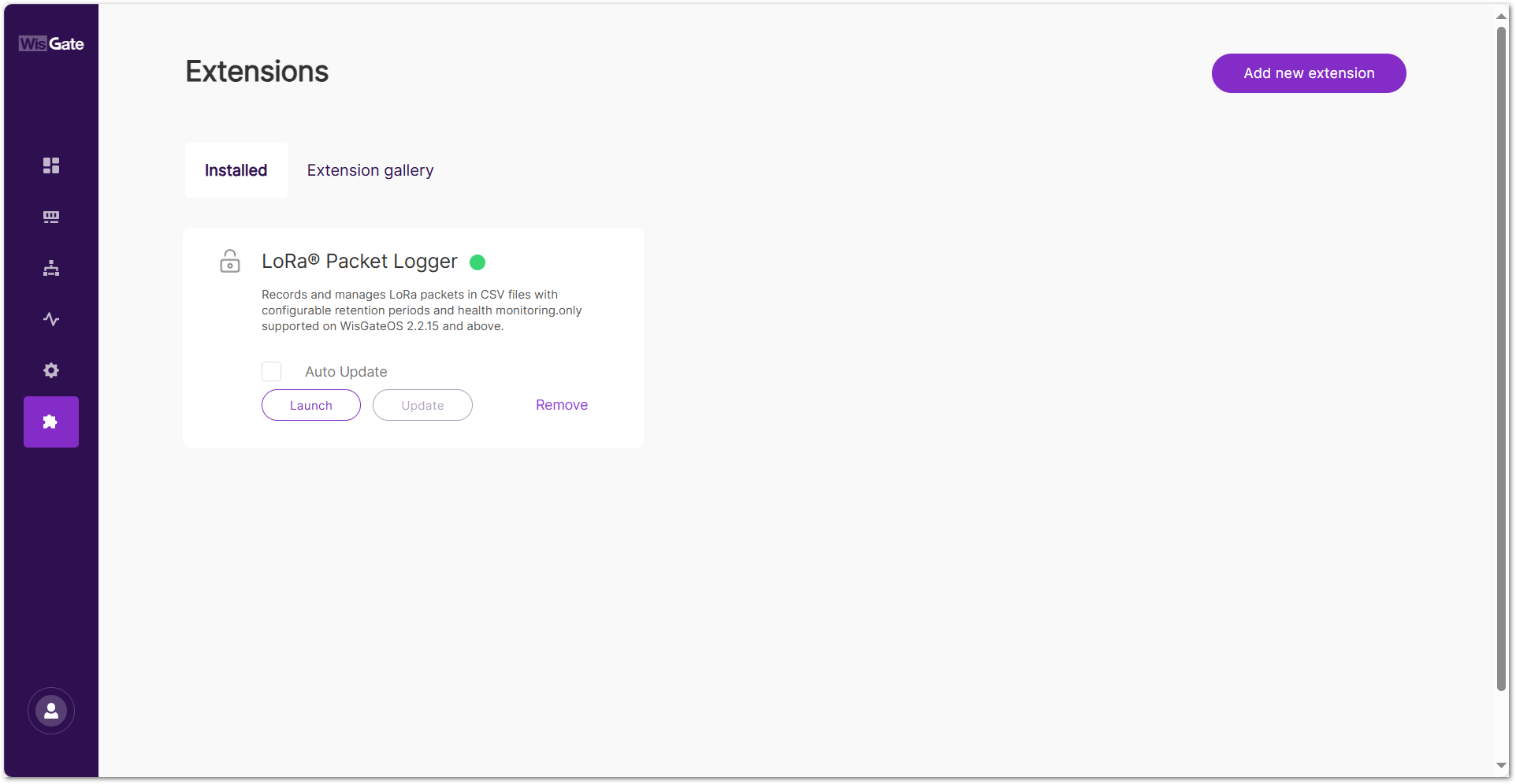 Figure 1: Extensions tab
- In Storage Duration, select how long to keep the LoRa logs. The configuration saves automatically after selection.
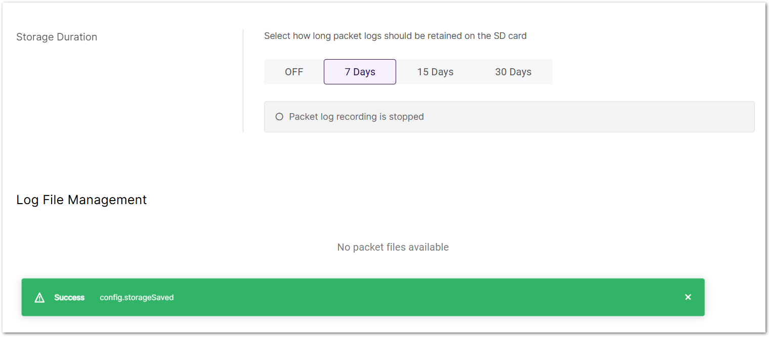 Figure 1: Set storage duration
-
OFF
-
7 Days
-
15 Days
-
30 Days
- When the status shows Currently recording packet logs to CSV file, the logger is active. Log files will appear under Log File Management, named as
lora-packets-YYYY-MM-DD.csv.
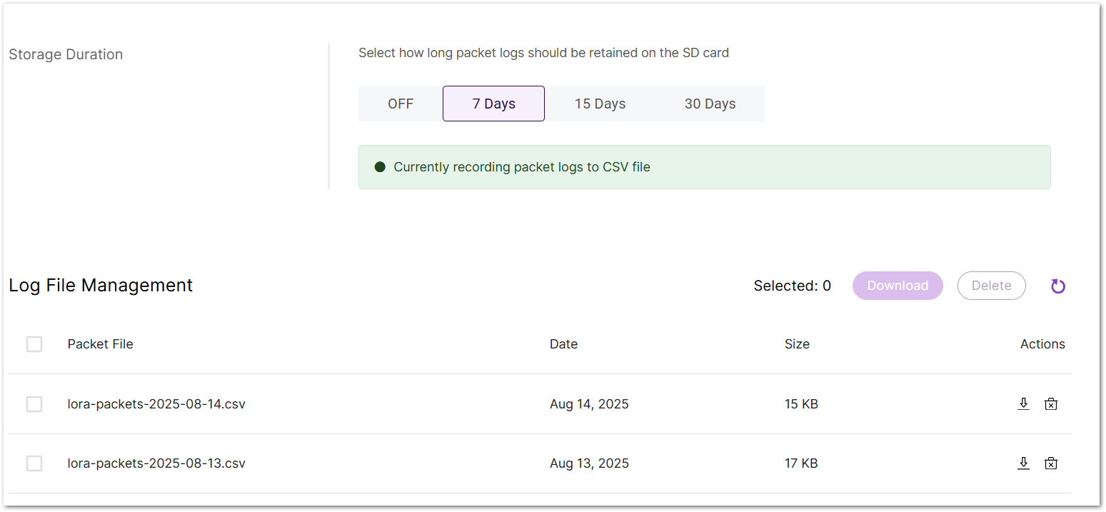 Figure 1: Recoding Packet Logs
Manage Packet Logs
- In Log File Management, check the box log files to select them.
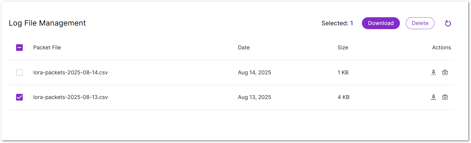 Figure 1: Manage Packet Logs
- Click Download to save the selected files to your local device, or Delete to remove them from the gateway.
To download or delete a single file, click the corresponding  or
or  icon under the Actions column.
Viewing CSV Files
Open the downloaded CSV file to view the recorded packet logs.
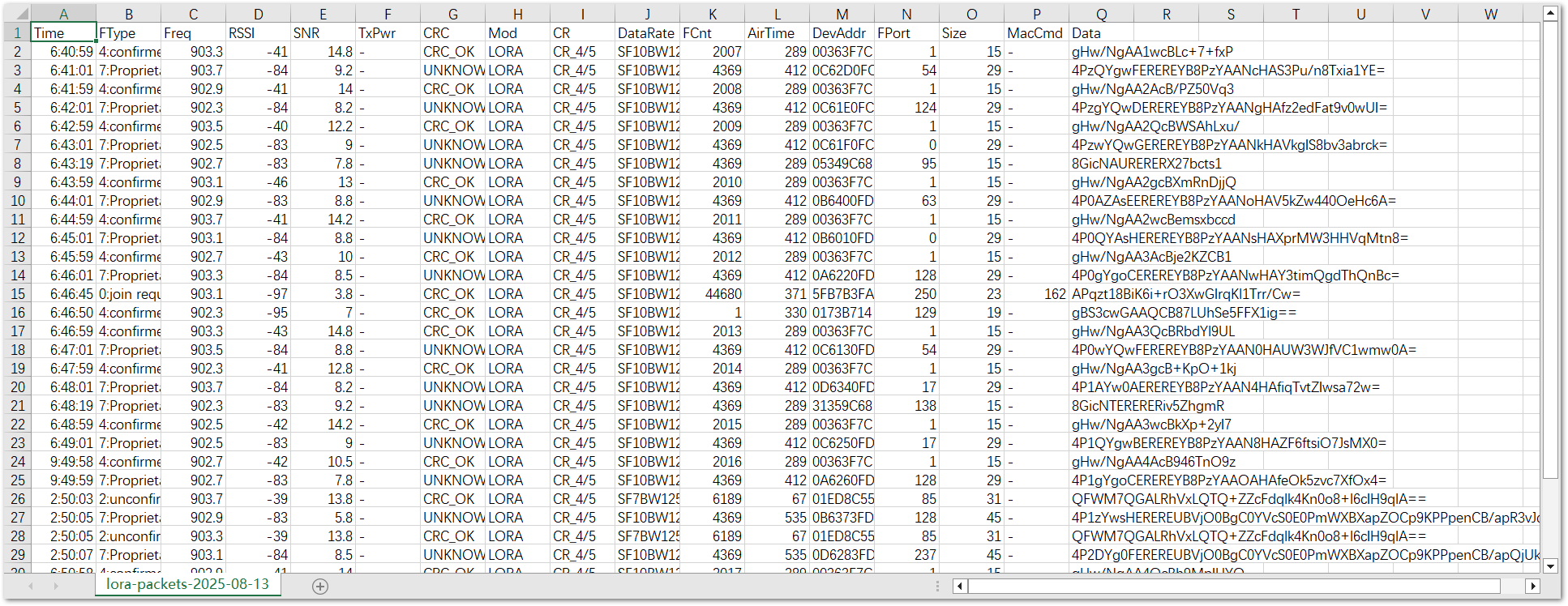 Figure 1: Check Logs
The downloaded CSV file contains the following columns:
| Field Name | Description |
|---|---|
| Time | Local time when the packet was received or transmitted by the gateway. |
| FType | Frame type and direction. |
| Freq | Center frequency (MHz) at which the packet was transmitted or received. |
| RSSI | Received Signal Strength Indicator (dBm); values closer to 0 indicate stronger signals. |
| SNR | Signal-to-Noise Ratio (dB), reflecting signal quality. |
| TxPwr | Transmit power (dBm); - means not recorded for uplink packets. |
| CRC | CRC check result (CRC_OK means passed, UNKNOWN means no CRC or undetectable). |
| Mod | Modulation type, e.g., LORA for LoRa modulation. |
| CR | Coding rate, e.g., CR_4/5. |
| DataRate | Data rate, e.g., SF10BW125 means spreading factor SF10 and bandwidth 125 kHz. |
| FCnt | Frame counter. |
| AirTime | Airtime (ms), the duration the packet occupies the radio channel. |
| DevAddr | LoRaWAN device address (hexadecimal). |
| FPort | LoRaWAN port number. |
| Size | Payload size in bytes. |
| MacCmd | MAC command(s), if present. |
| Data | Payload in Base64 encoding. |
TrackIT Data Broker
The TrackIT Data Broker extension enables RAK gateways to forward WisNode Tag data to the TrackIT platform.
TrackIT Data Broker support depends on the WisGateOS version:
- WisGateOS 2 v2.2.x (v2.2.2 or later): The TrackIT Data Broker is included in the gateway firmware. No additional installation is required.
- WisGateOS 2 v2.3.1 or later: Install the TrackIT Data Broker Extension before adding the gateway to TrackIT. Without the extension, the gateway cannot forward WisNode Tag data to TrackIT.
Install the TrackIT Data Broker Extension
To install the extension, follow the steps in the [Manually Upload an Extension](#Manually Upload an Extension) section.
Configure the TrackIT Data Broker Extension
Install and enable the extension before adding the gateway to TrackIT.
- To access the LoRa® Packet Logger extension, click Launch.
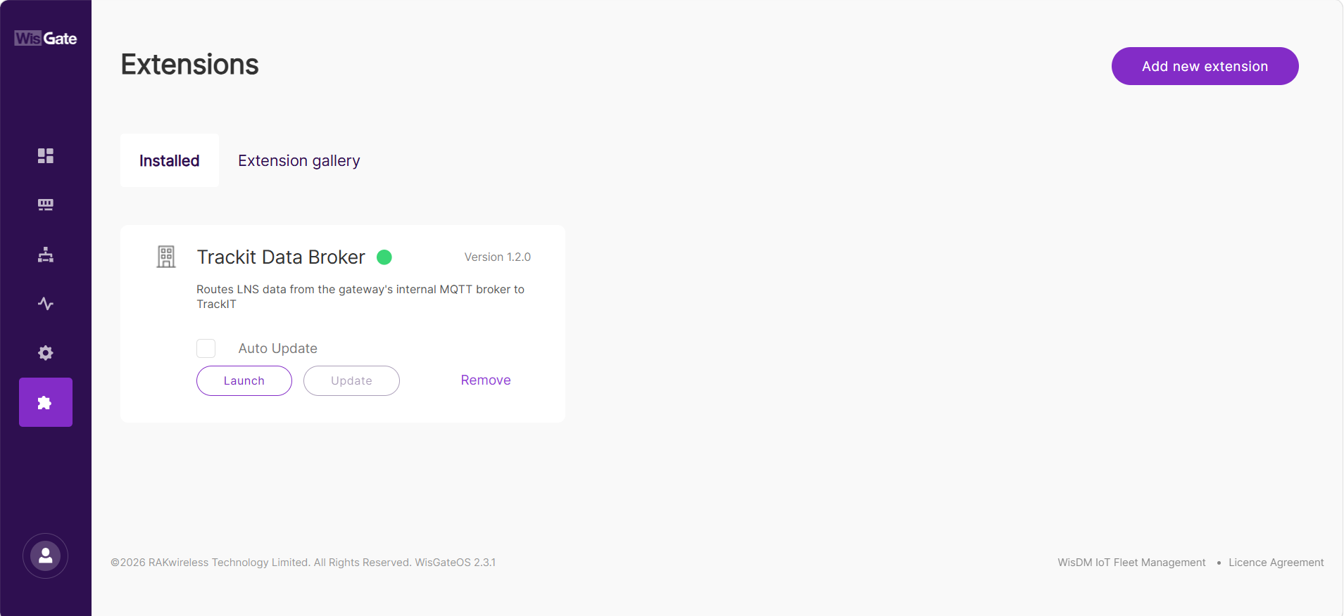 Figure 1: Manage TrackIT Data1
-
On the Configuration page, confirm that Enable TrackIT Data Broker is enabled and that the following statuses are displayed:
- Service status is
Running. - DBM dependency is
Ready.
- Service status is
-
Click Save changes to apply the updated service status. The button becomes available only after the switch setting is changed.
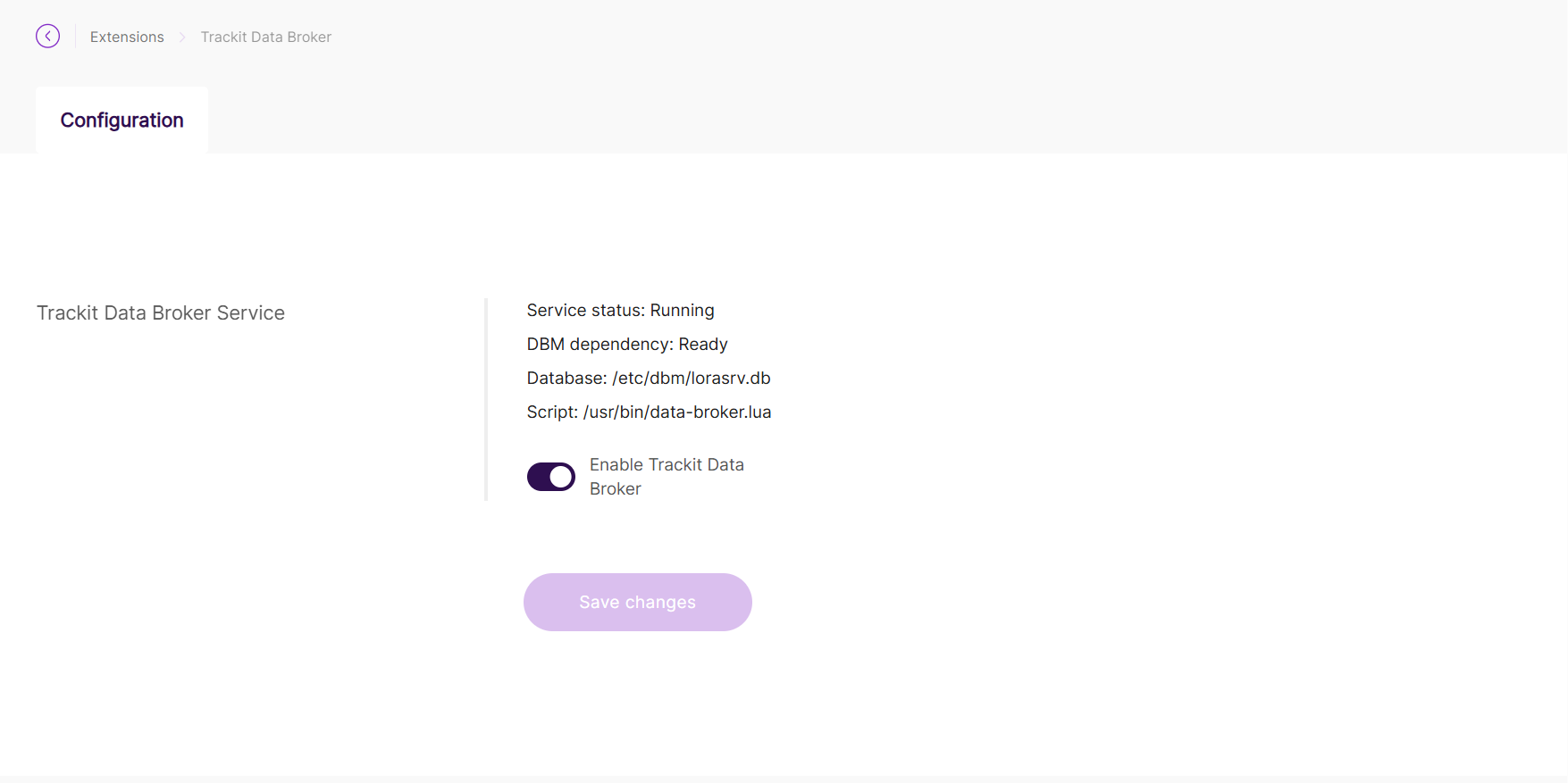 Figure 1: Manage TrackIT Data2
The Configuration page displays the current TrackIT Data Broker service status and related system information.
| Field | Description |
|---|---|
| Service status | Shows whether the TrackIT Data Broker service is running. If the status is Stopped or Not Running, the forwarding service is not active. |
| DBM dependency | Shows whether the database management dependency is ready. Ready indicates that the Data Broker can access the Built-in Network Server database. |
| Database | Displays the path to the local LoRaWAN database used by the Data Broker. |
| Script | Displays the path to the TrackIT Data Broker forwarding script. |
| Enable TrackIT Data Broker | Enables or disables the TrackIT Data Broker service. |
- When the page shows Service status:
Running, DBM dependency:Ready, and Enable TrackIT Data Broker is enabled, the service is operating normally. - Disabling the TrackIT Data Broker stops data forwarding to TrackIT. The gateway may still receive LoRaWAN packets from WisNode Tag, but the packets will not be forwarded to the TrackIT platform.


