LoRa Configuration
In WisGateOS 2, LoRa configuration supports three operating modes, allowing the gateway to connect to different LoRa network servers and manage LoRa communication efficiently:
- Built-in Network Server
The gateway acts as a central LoRa Network Server (LNS), processing packets locally and managing devices directly. It supports multi-gateway networking, allowing extender gateways to join the network and be managed from the central gateway interface. This mode allows independent operation without relying on external services. - Packet Forwarder
The gateway forwards packets to an external network server (e.g., TTN, ChirpStack) without local processing. The external network server handles packet processing, device management, and data routing. Suitable for integrating the gateway into an existing LoRaWAN network infrastructure. - Basics Station
The gateway uses a secure WebSocket (WSS) to communicate with a remote LoRaWAN network server. This mode offers enhanced security and stable connectivity, supporting dynamic updates and secure cloud-based communication.
Built-in Network Server
In WisGateOS 2, the gateway can operate as a Built-in Network Server, processing packets locally and managing LoRa devices directly without needing an external server.
Configuration
This section covers how to configure the gateway as a Built-in Network Server, including setting up the server and configuring its parameters.
Set Work Mode to Built-in Network Server
Select the Work mode to make the gateway act as its own LoRaWAN Network Server.
 Figure 1: Work mode
Set Log Level
Configure the log level for debugging and monitoring purposes.
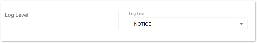 Figure 1: Log Level
- Error: Logs of error conditions.
- Warning: Logs of warning conditions.
- Notice: Logs of significant but normal events.
- Info: Logs of general system activity and information.
- Debug: Logs of all messages, including detailed debugging information.
Select Your Country & Region
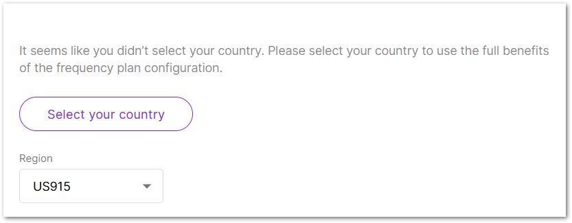 Figure 1: Select your country & region
Select your country(Optional)
The correct country setting ensures that the gateway operates in compliance with regional regulations. Transmit power is automatically limited to the maximum permitted, and LBT (Listen Before Talk) is enabled when required.
- Click Select your country.
- From the dropdown list, select the Country where the gateway will be deployed.
- Select the appropriate Region.
- Check the confirmation box to acknowledge compliance with local regulations.
- Click Confirm to save your settings.
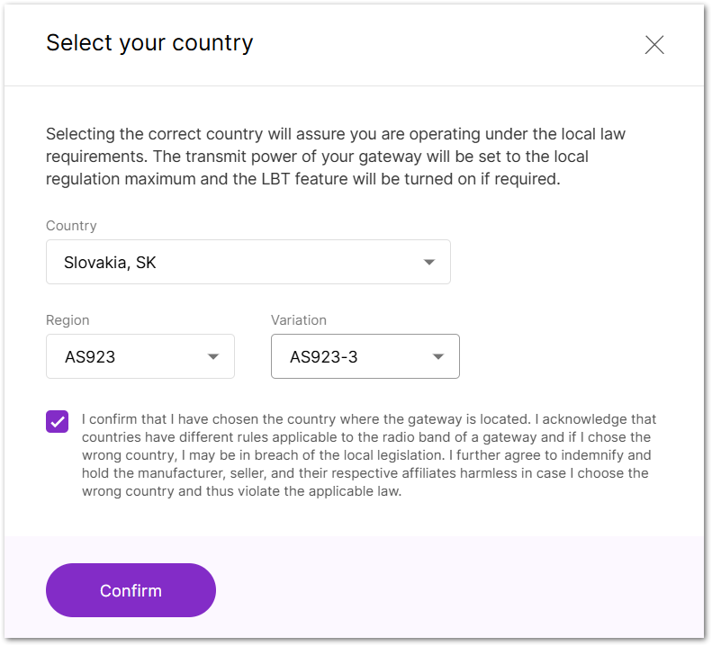 Figure 1: Country code settings
Region
Set the region here. The frequency plan can be switched for the following regions:
- US915, AS923, KR920, AS923
- EU868, RU864, IN865
- EU433
- CN470
- If you have already configured the Region in the Select your country settings, it will be automatically applied to the Region configuration.
- Different hardware supports different LoRaWAN regions.
- If your Region is set to AS923, you need to configure the Variation option, such as AS923-1/AS923-2/AS923-3/AS923-4.
Detailed Regional Frequency Settings
This section allows you to fine-tune sub-bands, LoRa/FSK channels, and network mode according to your deployment needs.
Click View detailed regional parameters of the frequency plan in the Frequency Plan section to expand and access advanced configuration options.
The frequency settings vary by region due to different radio regulations and frequency allocations. This affects the available channel types and the UI display.
- LoRaWAN Public: When enabled (by default), the gateway will process data from all end devices. If you want to create a private network, you can turn it off. The gateway will process the data only from the end devices, whose sync word is changed to private.
- Frequency Sub-Band: Select the specific frequency sub-band based on the region's frequency plan.
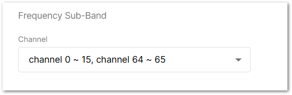 Figure 1: Frequency Sub-Band Selection
- Multi-SF LoRa Channel Frequency (MHz): Set the frequency for the Multi-SF LoRa channel.
- Standard LoRa Channel Frequency (MHz): Set the frequency for the standard LoRa channel.
- FSK Channel Frequency (MHz): Set the frequency for the FSK channel.
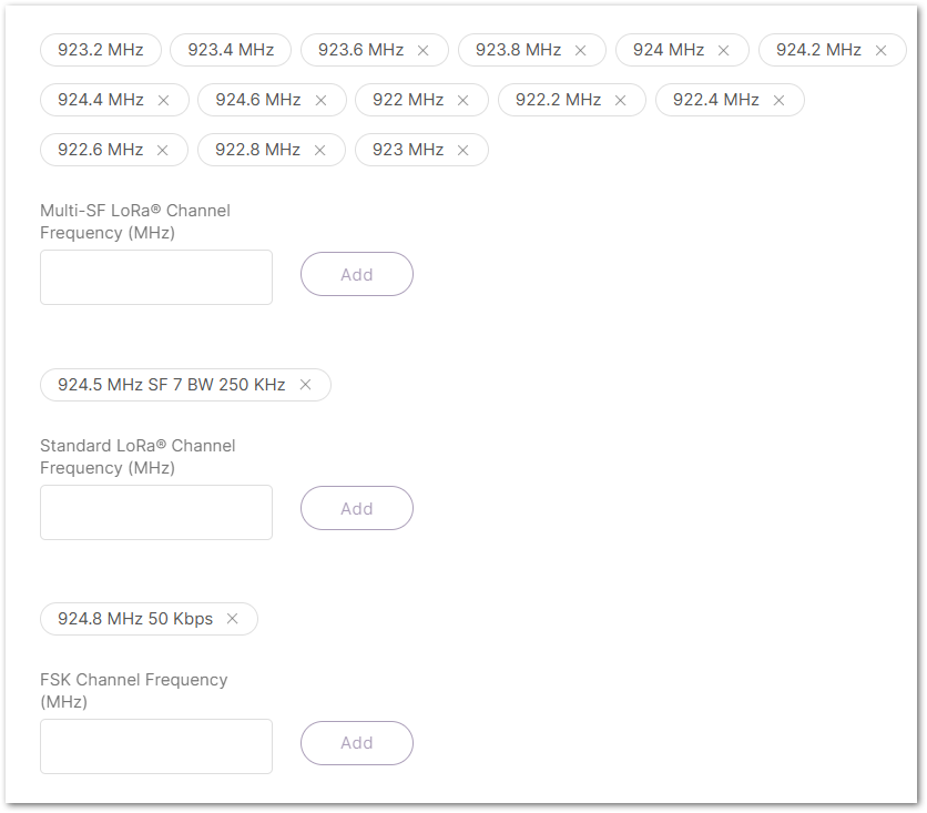 Figure 1: Frequency settings
Configure Network Server Parameters
Click on Network server parameters are used to configure general setup for your LoRa built-in server. This section is required for filling-in. to expand the settings menu.
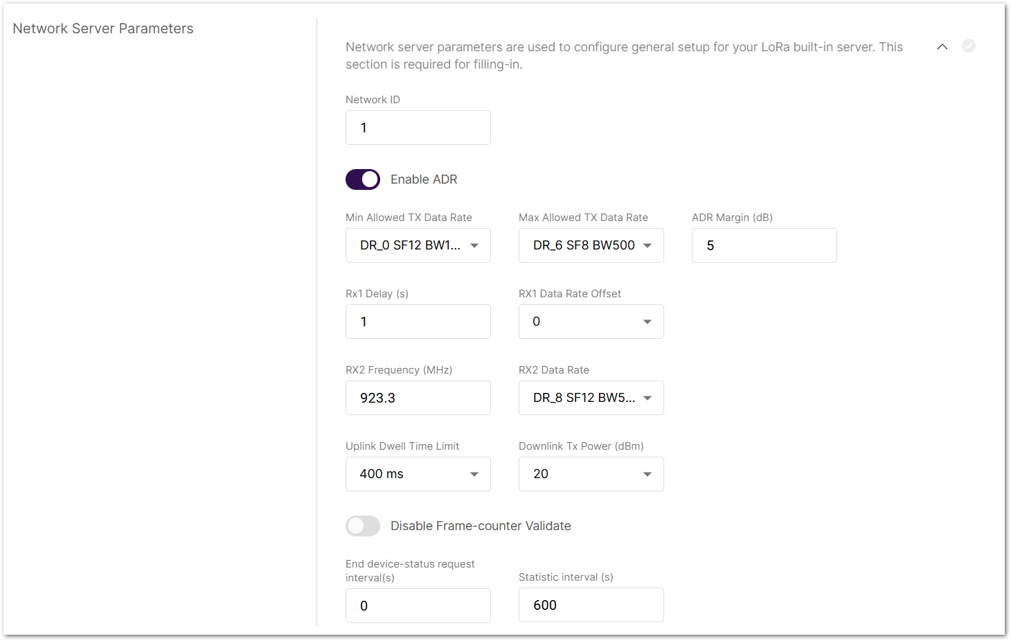 Figure 1: Network Server Parameters
- Network ID: This is a decimal number to distinguish between networks if deploying multiple ones.
- Enable ADR: Enables or disables Adaptive Data Rate (ADR). When enabled, the server will automatically adjust data rates, airtime, and energy consumption based on current network conditions.
- Min Allowed TX Data-Rate: Sets the minimum transmission data rate. Depends on the Region.
- Max Allowed TX Data-Rate: Sets the maximum transmission data rate. Depends on the Region.
- ADR Margin (dB): Only visible when ADR is enabled. This sets the margin value in dB to avoid overestimating the data rate, which could lead to performance issues (e.g., increased error rate and reduced range).
- Rx1 Delay (s): Delay of the first receive window (RX1) in seconds.
- RX1 Data Rate Offset: Determines the data rate for downlink frames sent in the RX1 window. By default, it is 0 – identical to the uplink.
- RX2 Frequency (MHz): Sets the frequency of the second receive window (RX2).
- RX2 Data Rate: Sets the data rate for frames sent in the second receive window.
- Uplink / Downlink Dwell Time Limit: Sets the uplink/downlink Dwell Time limit. Note that these two configuration options are only valid for specific regions.
- Downlink Tx Power (dBm): It is useful if you want to use a larger antenna with more gain. Values from -6 to 20 are permissible.
- Disable Frame-counter Validate: This function turns on/off the Frame counter validation.
- End device-status request interval (s): This shows how often the end devices should be polled for their status log level.
- Statistic interval (s): This shows how often the statistics will be gathered.
Enable Packet Filter
Set a filter for the packets from chosen devices (disabled by default).
Click on Allows to optimize bandwidth by filtering and forwarding packets from chosen end devices to expand packet filter settings. If White List Mode and Auto Filter are enabled, these are the following options:
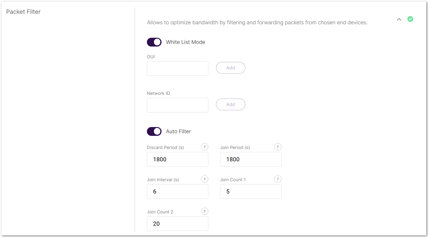 Figure 1: Packet Filter
- OUI: Filters devices based on the first 3 bytes (6 hexadecimal characters) of the DevEUI, which typically identify the device manufacturer.
- Network ID: A number between 0 and 127 (decimal), derived from the first 7 most significant bits (MSB) of a device's DevAddr. For example, a DevAddr starting with 0x26 (00100110 in binary) has the first 7 bits 0010011, which equals decimal 19.
- Discard Period (s): The period threshold of discard time for nodes (in seconds).
- Join Period (s): The period threshold of statistics on the latest join request (in seconds).
- Join Interval (s): The time interval threshold between two consecutive join requests from the same device EUI (in seconds).
- Join Count 1: Maximum count of join requests allowed during the Join Interval.
- Join Count 2: Maximum count of join requests allowed during the Join Period.
Set Up Gateway Backend for Multi-Gateway Networking
The Gateway Backend defines how the central gateway communicates with extender gateways through MQTT. Extender gateways connect by subscribing to the central gateway's built-in MQTT broker, and each extender is registered in the central gateway. This creates a multi-gateway network in which extender gateways forward uplinks from distant nodes to the central gateway, effectively extending coverage and centralizing device management.
To extend the settings field, click on Configure the Gateway Backend to allow the central gateway and extenders to communicate via MQTT.
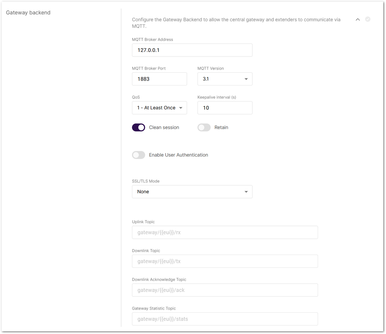 Figure 1: Gateway backend
- MQTT Broker Address: The IP address of the MQTT broker (default:
127.0.0.1for the built-in broker). When using the built-in broker (127.0.0.1), SSL/TLS certificate configuration is not supported, because secure connections are only applicable when connecting to an external MQTT broker. - MQTT Broker Port: The port used by the broker (default:
1883). - MQTT Version: Choose between V3.1 and V3.1.1. There is very little difference between them, more information can be found on the GitHub repository.
- QoS (Quality of Service):
- 0 - At Most Once
- 1 - At Least Once
- 2 - Exactly Once
- Keepalive interval (s): Interval in seconds to keep the connection alive (default:
10). - Clean session: When enabled, the broker does not store subscription or undelivered messages.
- Retain: When enabled, the last message will be retained.
- Enable User Authentication: Enable authentication using username and password (disabled by default).
- SSL/TLS Mode: Configure secure connection
- None
- CA signed server certification
- Self-signed server certification
- Self-signed server & client certification
- TLS Version: Choose between TLS v1.1 and TLS v1.2.
- Uplink Topic/Downlink Topic/Downlink Acknowledge Topic/Gateway Statistic Topic: Predefined MQTT topics for uplink, downlink, and status updates.
Configure Class B Beaconing
Enable time-synchronized beaconing and set ping slot parameters for Class B end devices. This option is only available on certain gateway models with GPS capability.
To expand the menu, click on Configure the beacon period and ping slots of class B devices to use time-sync beacons sent by the gateways.
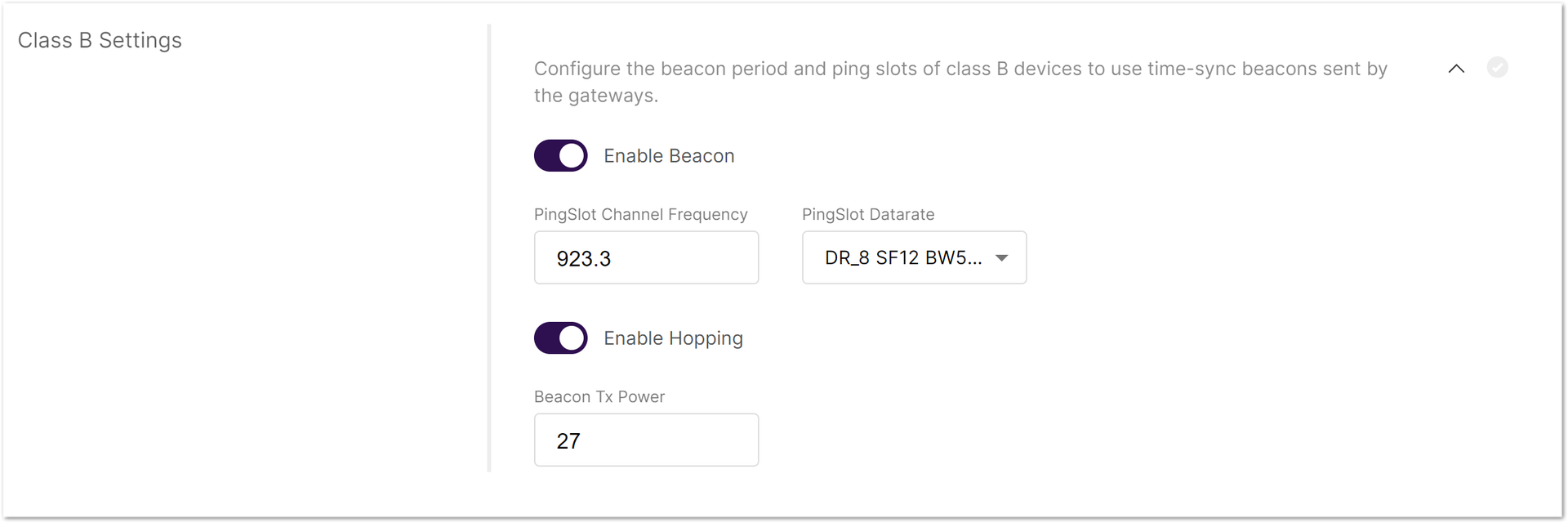 Figure 1: Class B Settings
- Enable Beacon: Enables/disables Class B beaconing.
- PingSlot Channel Frequency: The frequency used for the beacon ping.
- PingSlot Datarate: Minimum duration of each beacon ping slot.
- Enable Hopping: Enables/disables Class B hopping as the class B beacon is transmitted following a frequency hopping pattern.
- Beacon Frequency (MHz): The frequency of the beacon. If frequency hopping is enabled, this option does not appear.
- Beacon TX Power: The transmit power of the beacon ping.
Integrate with External Platforms
The Integration Interface forwards uplink data received by the built-in network server to external MQTT-compatible platforms or cloud services (e.g., AWS IoT Core) for visualization, processing, and integration.
To expand the menu, click on Configure the Integration Interface to forward all received data to an external network server. The settings change depending on the chosen Integration mode.
 Figure 1: Integration Interface Parameters
- Enable Integration Interface: Enables the integration interface.
- Generic MQTT: In this configuration, the gateway acts as an MQTT client that publishes messages to an external MQTT broker.
- MQTT Broker Address: The IP address of the MQTT broker.
- MQTT Version: Choose between V3.1 and V3.1.1. There is very little difference between them, more information can be found on GitHub repo.
- QoS: Quality of Service level:
- 0 - At Most Once
- 1 - At Least Once
- 2 - Exactly Once
- Keepalive interval (s): Interval in seconds to keep the connection alive (default:
10). - Clean session: When enabled, the broker does not store session data.
- Retain: If enabled, the last published message is retained.
- Client ID: ID used to associate with the topic (auto-generated if left empty).
- Enable User Authentication: Enable authentication using username and password.
- SSL/TLS Mode: Configure secure connection
- None
- CA signed server certification
- Self-signed server certification
- Self-signed server & client certification
- TLS Version: Choose between TLS v1.1 and TLS v1.2.
- Join Topic / Uplink Topic / Downlink Topic / Downlink Acknowledge Topic / Status Topic: Predefined MQTT topics used to publish messages.
- AWS IoT Core:
- AWS IoT Core endpoint URL: The AWS endpoint address.
- AWS IoT Core endpoint Port: The port used by the AWS server.
- Root CA: CA certificate provided by AWS IoT Core.
- Certificate: Gateway certificate generated by AWS IoT Core.
- Key: Private key for the gateway, generated by AWS IoT Core.
Application and Device Management
The Applications tab is available only when the gateway is in Built-in Network Server mode. Here, you can create applications and register end devices.
Create an Application
Applications group LoRaWAN devices for management.
- Navigate to the LoRa > Applications tab.
- To add a new application, click Add application or add one now.
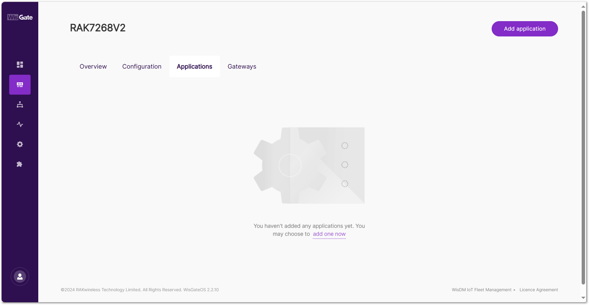 Figure 1: Applications tab
- Set the following parameters:
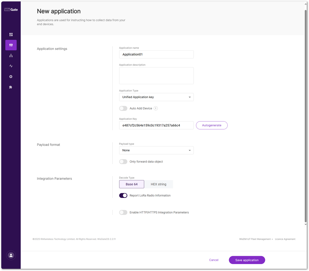 Figure 1: Set parameters
- Application name: A unique name for the application.
- Application description: (Optional) description of the application.
- Application Type
- Unified Application key: All devices will use the same application key.
- Separate Application keys: Each device or group of devices has a unique key.
- Auto Add Device: When enabled, devices with matching AppKey and Application EUI will be added automatically after a successful join request. This feature applies only to OTAA devices.
- Application Key: Required for Unified Application Key setup.
- Application EUI: Required for automatic device registration when Auto Add Device is enabled.
- Payload type
- None: No specific payload format.
- CayenneLPP: Payload format based on the Cayenne Low Power Payload (LPP) standard.
- Only forward data object: When enabled, the gateway will only forward the raw data object to the server without processing or decoding it.
- Decode Type
- Base 64
- HEX string
- Report LoRa Radio Information: When enabled, the gateway will include LoRa signal data (RSSI, SNR, etc.) in the payload sent to the server.
- Enable HTTP/HTTPS Integration Parameters: When enabled, uplink data and events are forwarded to external HTTP/HTTPS endpoints.
- Header name
- Header value
- Uplink data URL
- Join notification URL
- Ack notification URL
- Device-status notification URL
- Maximum number of concurrent connections
- Maximum length of queue
- Click Save application.
Add Devices
If Auto Add Device is enabled in the application settings, devices are automatically registered upon a successful join request. Otherwise, you can add devices manually or using a CSV file. Both methods support batch device registration.
Configure Device Information
- Navigate to the LoRa > Applications.
- Click on the application where the device should be added.
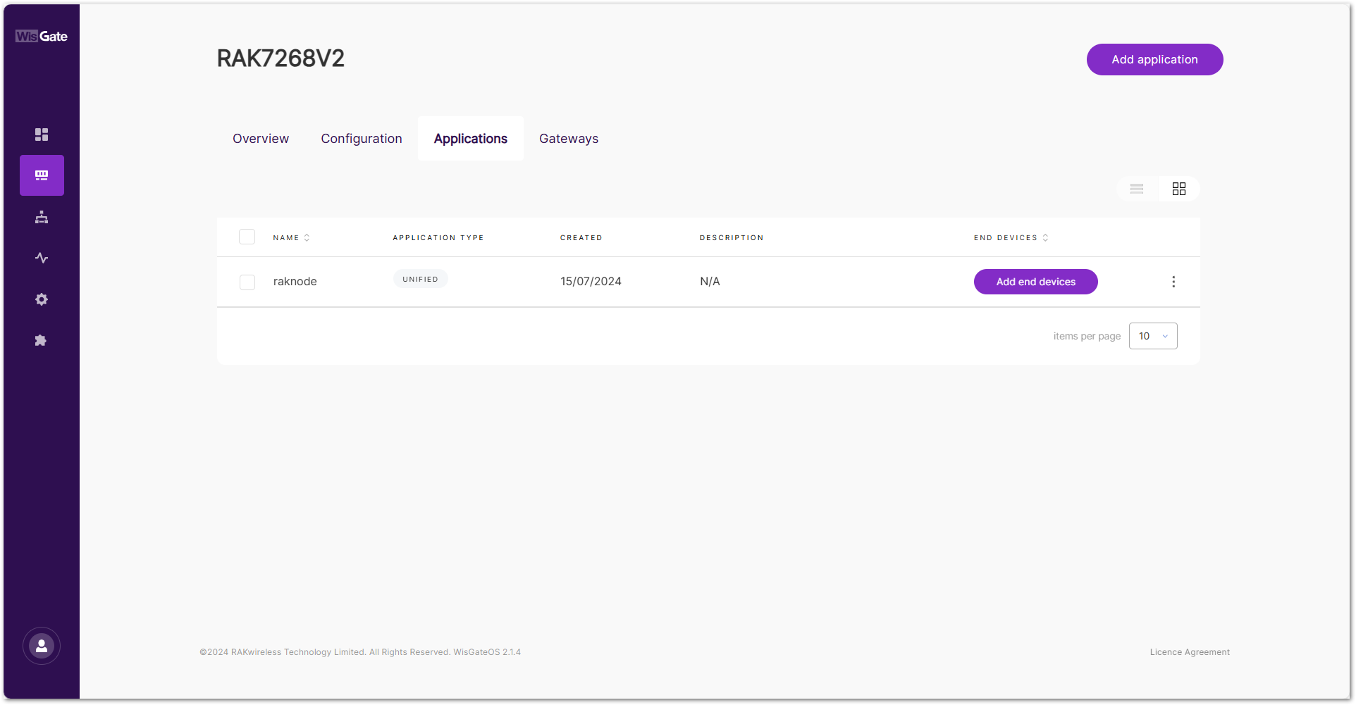 Figure 1: Application listNOTE
You can also click "Add end devices" in the END DEVICES list. (This button will only appear if no end devices are registered.)
- In the End devices tab, click Add end device or add some now.
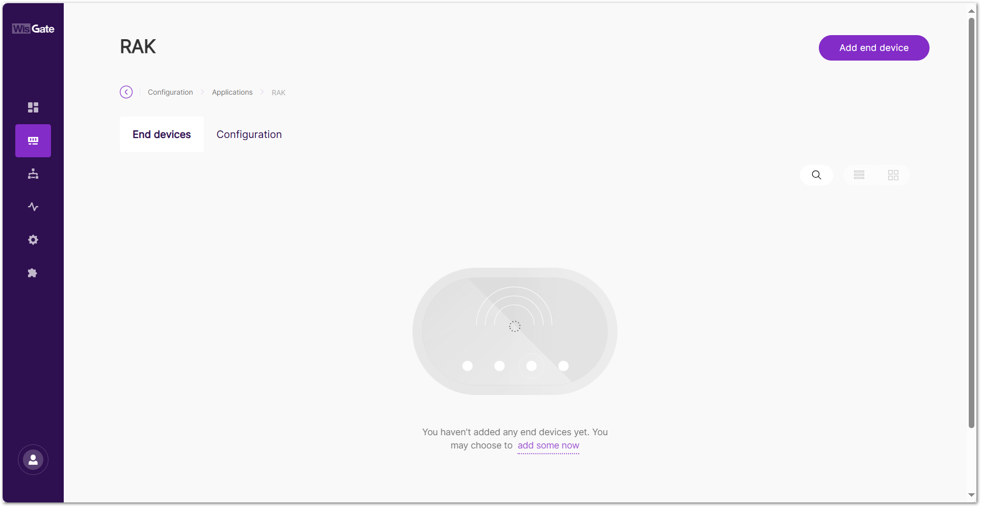 Figure 1: Add an end device
- Set the following device parameters:
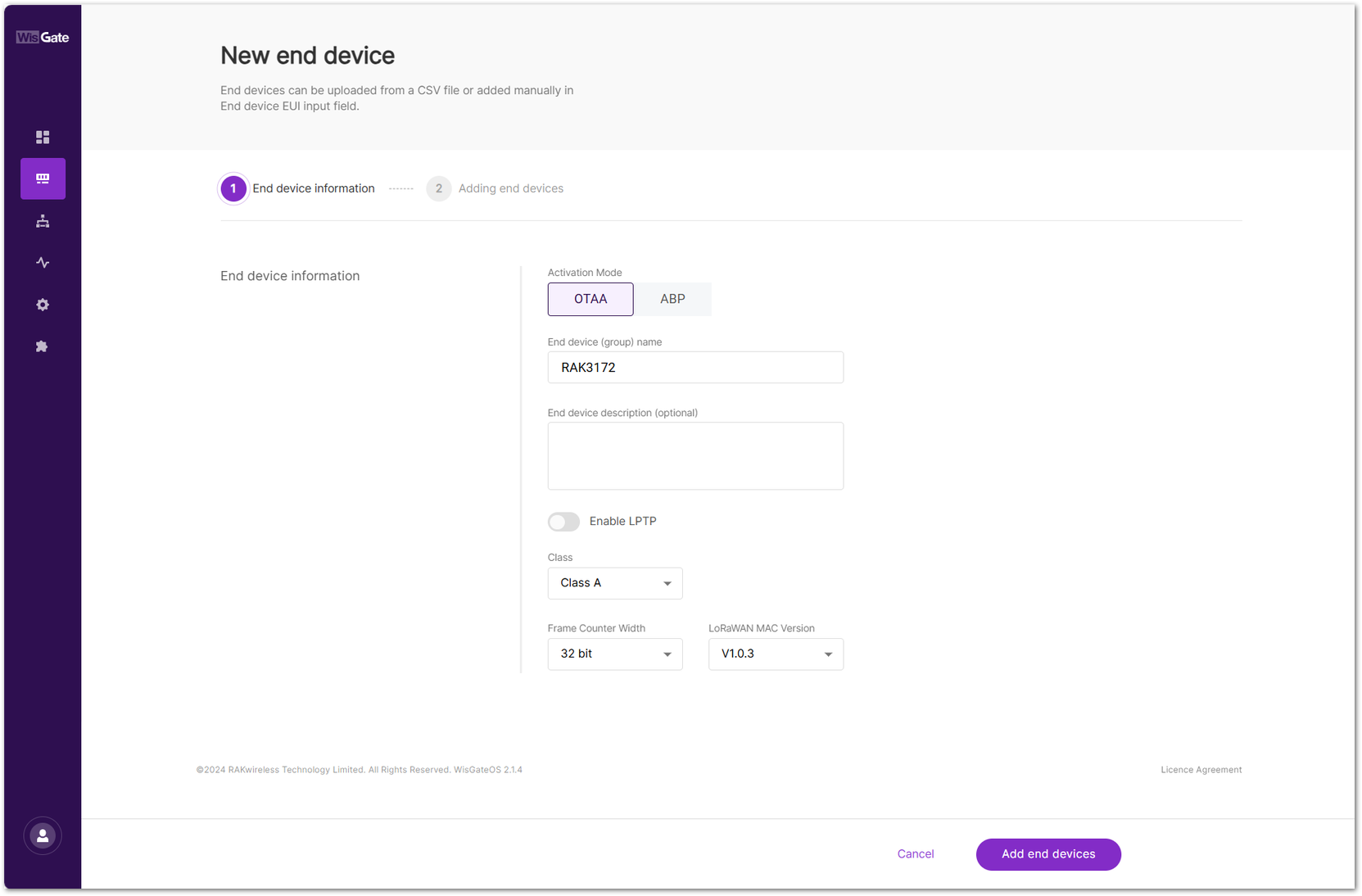 Figure 1: Configuration page
- Activation Mode
- OTAA: Over-The-Air-Activation (OTAA).
- ABP: Activation-By-Personalization (ABP).
- End device (group) name: Enter a name for the device or group of devices.
- End device description (optional): Provide a brief description of the device or group of devices.
- Enable LPTP: LoRa Private Transport Protocol (LPTP) is a RAK proprietary message splitting protocol, which can send data with a length exceeding the maximum permissible size, using multiple messages.
- Application Key: Required for LoRaWAN OTAA devices. Enter the AppKey during registration when using Separate Application keys.
- Class: Class A / Class B / Class C
NOTE
If the end device is configured as Class B, ensure that the gateway supports time synchronization (e.g., GPS) and has Class B beaconing enabled. Otherwise, the device may not function properly in Class B mode.
- Application Session Key: Required for ABP devices.
- Network Session Key: Required for ABP devices.
- Frame Counter Width: Defines the frame counter size for message tracking.
- LoRaWAN MAC Version: V1.0.2 / V1.0.3
- LoRaWAN Regional Parameters reversion: Defines the revision of the Regional Parameters specification (A or B). This setting is available only when the LoRaWAN MAC Version is 1.0.2.
- To save the changes, click Add end devices.
Manually Add Devices
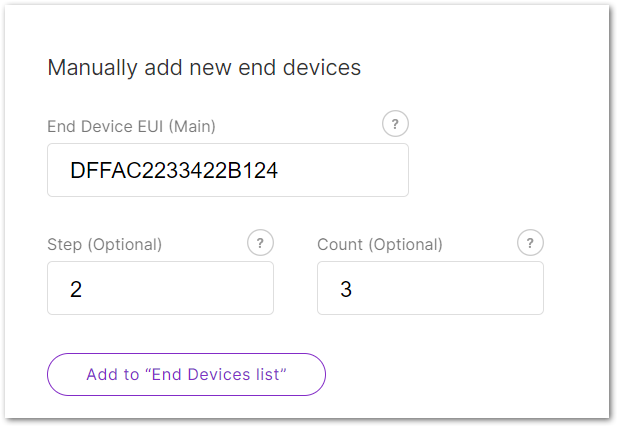 Figure 1: Manual Method
-
Enter the following:
- End Device EUI (Main): Fill in the device's unique EUI (Required).
- End Device Address (Main): Fill in the device's unique address (Required for ABP mode).
- Step (Optional): Use this to auto-generate multiple devices in sequence.
- Count (Optional): Number of devices to generate.
-
Click Add to "End Devices List" and the system will automatically verify the device information.
- Correct devices will appear under End devices list.
- Duplicate devices will appear under End devices with error for correction.
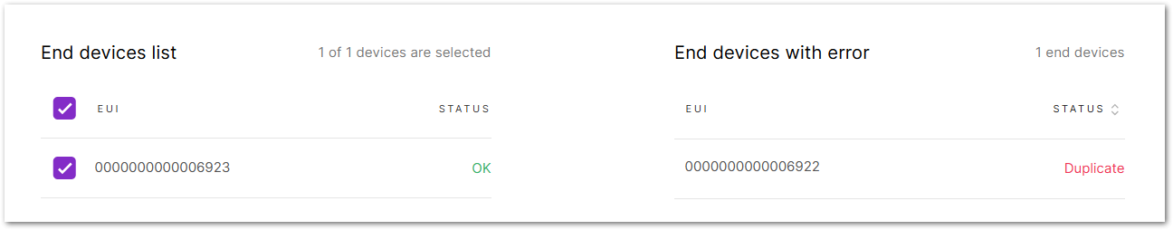 Figure 1: Add devices to the List
- To add the uploaded devices, click Add end devices.
- Click Add to confirm and proceed.
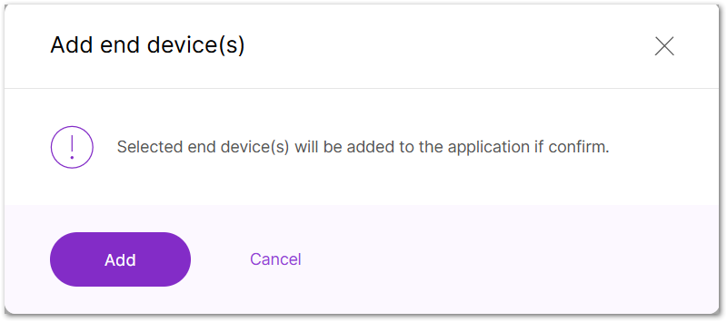 Figure 1: Confirm adding devices
Add Devices Using CSV File
For batch registration of multiple devices, using a CSV file is more efficient.
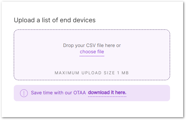 Figure 1: CSV Method
- You can create a CSV file in two ways:
- Download the template by clicking download it here.
- Or create your CSV file manually.
NOTE
The CSV file must include the following fields:
-
end device EUI : Enter the unique 64-bit EUI, shown as a 16-character hexadecimal string.
-
end device address: Enter the 32-bit device address, shown as an 8-character hexadecimal string (required for ABP mode).
Ensure the file size does not exceed 1 MB.
-
- Click choose file or drag and drop your CSV file into the upload box.
- After importing the CSV file, the system will automatically verify the device information.
- Correct devices will appear under End devices list.
- Duplicate devices and devices with invalid fields will appear under End devices with error.
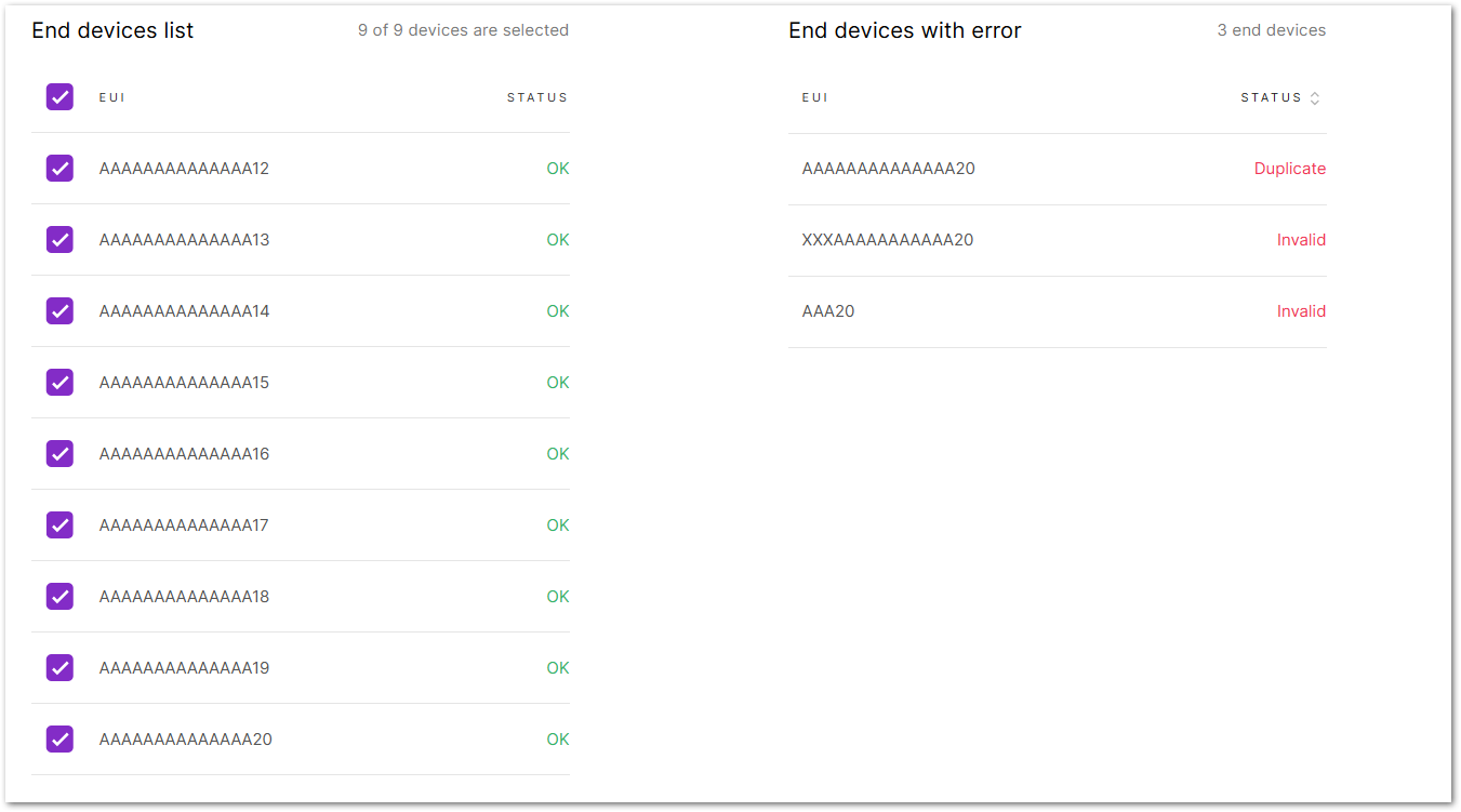 Figure 1: Add devices to the List
- To add the uploaded devices, click Add end devices.
- Click Add to confirm and proceed.
Figure 1: Confirm adding devicesOnce the device successfully joins or communicates, its "LAST SEEN" field will be updated in the End Devices List will be updated with a timestamp (e.g., 5s ago), showing when the device was last active.
Manage Applications
View/Modify Application Settings
- Navigate to the LoRa > Applications. View all added applications in this panel.
- Click the target application to go to its Configuration tab, or click (
 ) and choose Edit Configuration.
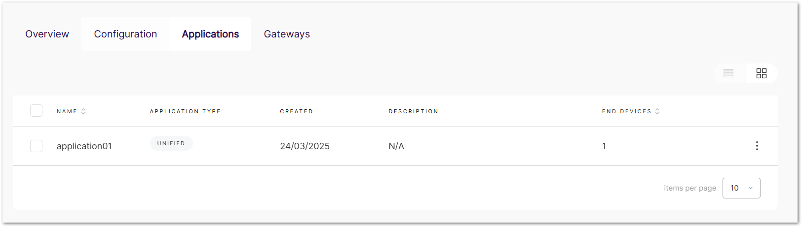 Figure 1: Application list
- In the Configuration tab, you can view and modify the application settings.
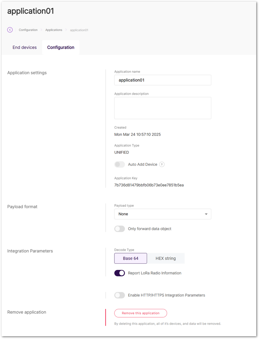 Figure 1: Application configuration
Delete Application
Once deleted, the applications cannot be recovered. Proceed with caution.
- Delete a Single Application
- Navigate to the target application's Configuration tab.
- Click Remove this application.
- Batch Delete Applications
- Go to LoRa > Applications.
- Select checkbox(es) for target application(s).
- Click Delete.
Manage Devices
View/Modify Device Settings
- Navigate to the LoRa > Applications.
- Click the target application to go to its End devices tab, or click () and choose View end devices.
- In the End devices tab, all devices in the application can be viewed here.
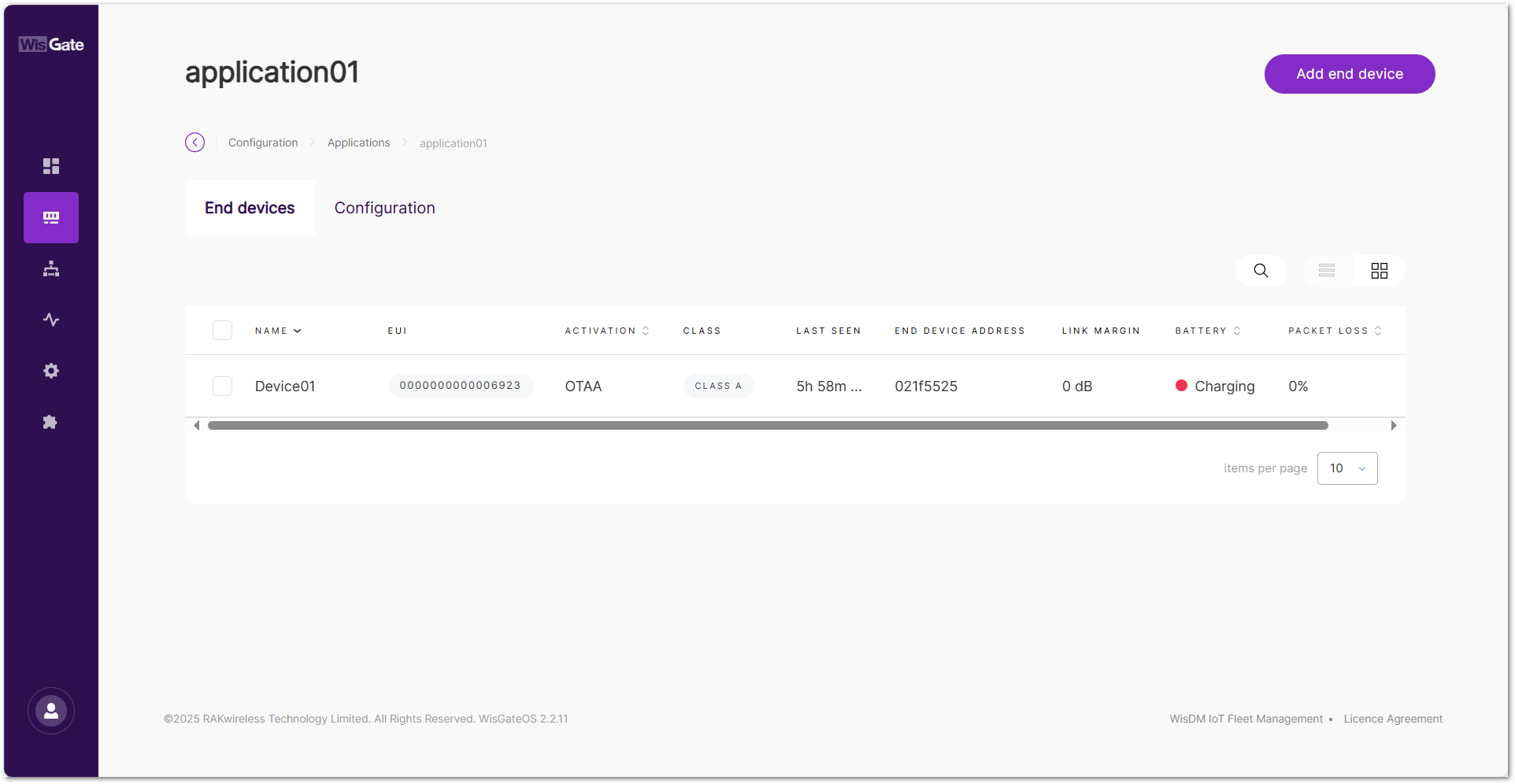 Figure 1: Device list
- Click the target device to view or modify its information under the Configuration tab.
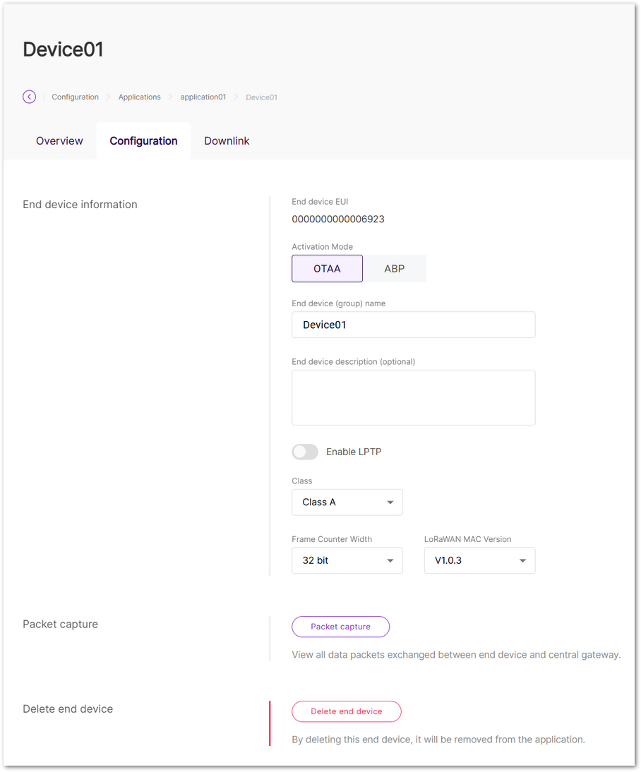 Figure 1: Device configuration
Packet Capture
Use the Packet Capture tool to view all packets exchanged between the end device and the gateway.
- Go to the Configuration tab of the device, then click Packet capture.
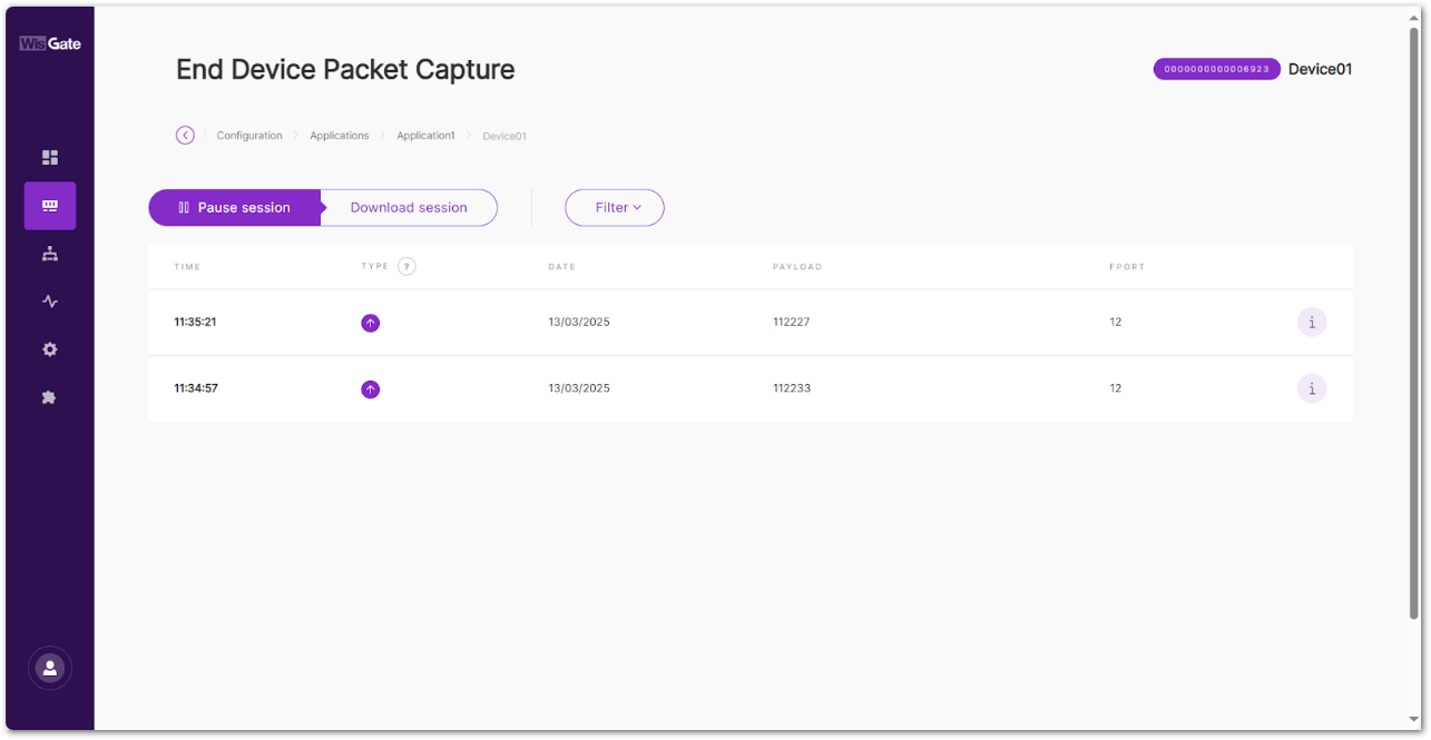 Figure 1: Packet capture
- Pause/Restart session: Pauses or restarts the session.
- Download session: Downloads a
.jsonfile with packets data in it. - Filter: The button drops-down a filter menu.
- Type: LoRaWAN message type.
- Frequency: The frequency on which the packet is received/sent.
- RSSI: Range of the RSSI.
- SNR: Range of the SNR.
- Hide CRC_ERR Packets: When enabled, the filter will hide all packets with CRC Error.
- Reset filter: Reset the filter to default.
Export End Device Information
Export device profiles including:
- End Device EUI
- Device Name
- Activation Mode (OTAA/ABP)
- DevAddr
- AppKey (encrypted)
- Go to LoRa > Applications > Your Application > End devices.
- Select target device(s).
- Click Export end device info.
Downlink
Send downlink messages to the end device.
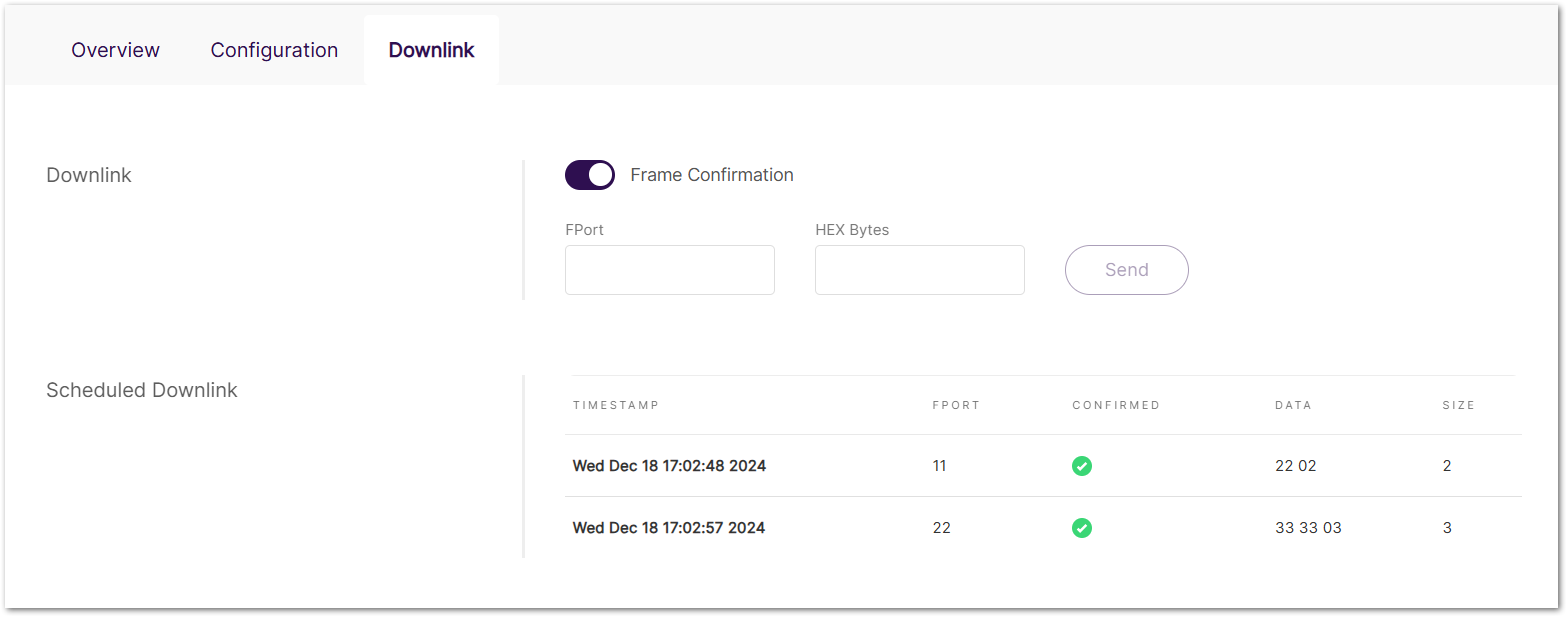 Figure 1: Downlink
- Frame Confirmation: Enable or disable frame confirmation for the downlink message.
- FPort: Port number used for the downlink message.
- HEX Bytes: Hexadecimal-encoded message content.
- Scheduled Downlink: List of sent downlink data.
- TIMESTAMP: Time the downlink message was sent.
- FPORT: Port number used for the message.
- CONFIRMED: Indicates whether the downlink message was confirmed.
- DATA: Content of the downlink message in hexadecimal format.
- SIZE: Size of the downlink message in bytes.
Overview
The Overview tab provides a summary of the device's current status and performance. It includes key metrics and visualizations to monitor network activity and signal quality.
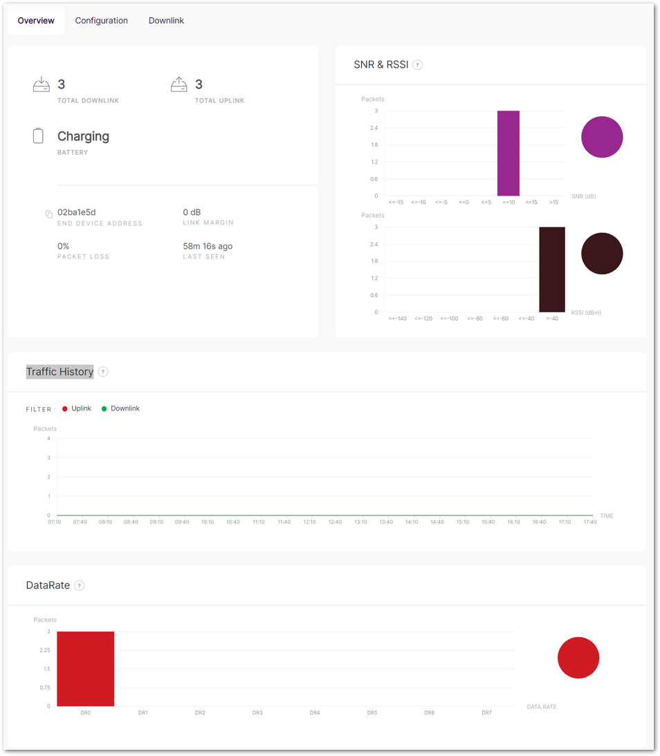 Figure 1: Overview
Device Status and Summary
- TOTAL DOWNLINK: Number of downlink messages sent to the device.
- TOTAL UPLINK: Number of uplink messages received from the device.
- BATTERY: Current battery status (e.g., charging).
- END DEVICE ADDRESS: Unique identifier of the end device.
- LINK MARGIN: Signal-to-noise ratio (SNR) margin in dB.
- PACKET LOSS: Percentage of lost packets during transmission.
- LAST SEEN: Time since the last communication with the device.
SNR & RSSI
Displays signal quality metrics through bar graphs:
- SNR (Signal-to-Noise Ratio): Distribution of SNR values for received packets (in dB).
- RSSI (Received Signal Strength Indicator): Distribution of RSSI values for received packets (in dBm).
Traffic History
Tracks uplink and downlink message activity over time:
Data Rate
Shows the distribution of packets sent and received at different data rates:
Delete Device
Once deleted, the devices cannot be recovered. Proceed with caution.
- Delete a Single Device
- Navigate to the device's Configuration tab.
- Click Delete end device.
- Batch Delete Devices
- Go to LoRa > Applications > Your Application > End devices.
- Select target device checkbox(es).
- Click Delete.
Extender Gateway Management
The Gateways tab is available only when the gateway is operating in Built-in Network Server mode. This section describes how to add and manage extender gateways in Built-in Network Server (LNS) mode. These extender gateways can be connected to the central gateway to extend LoRaWAN coverage and increase network capacity.
Add an Extender Gateway
- Navigate to the LoRa > Gateways tab.
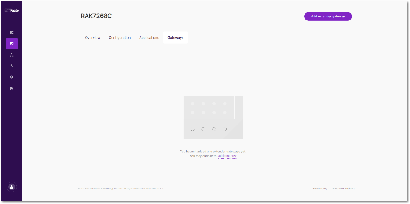 Figure 1: Gateways tab
- To add an extender gateway, click the Add extender gateway.
- In the new window, configure the following information.
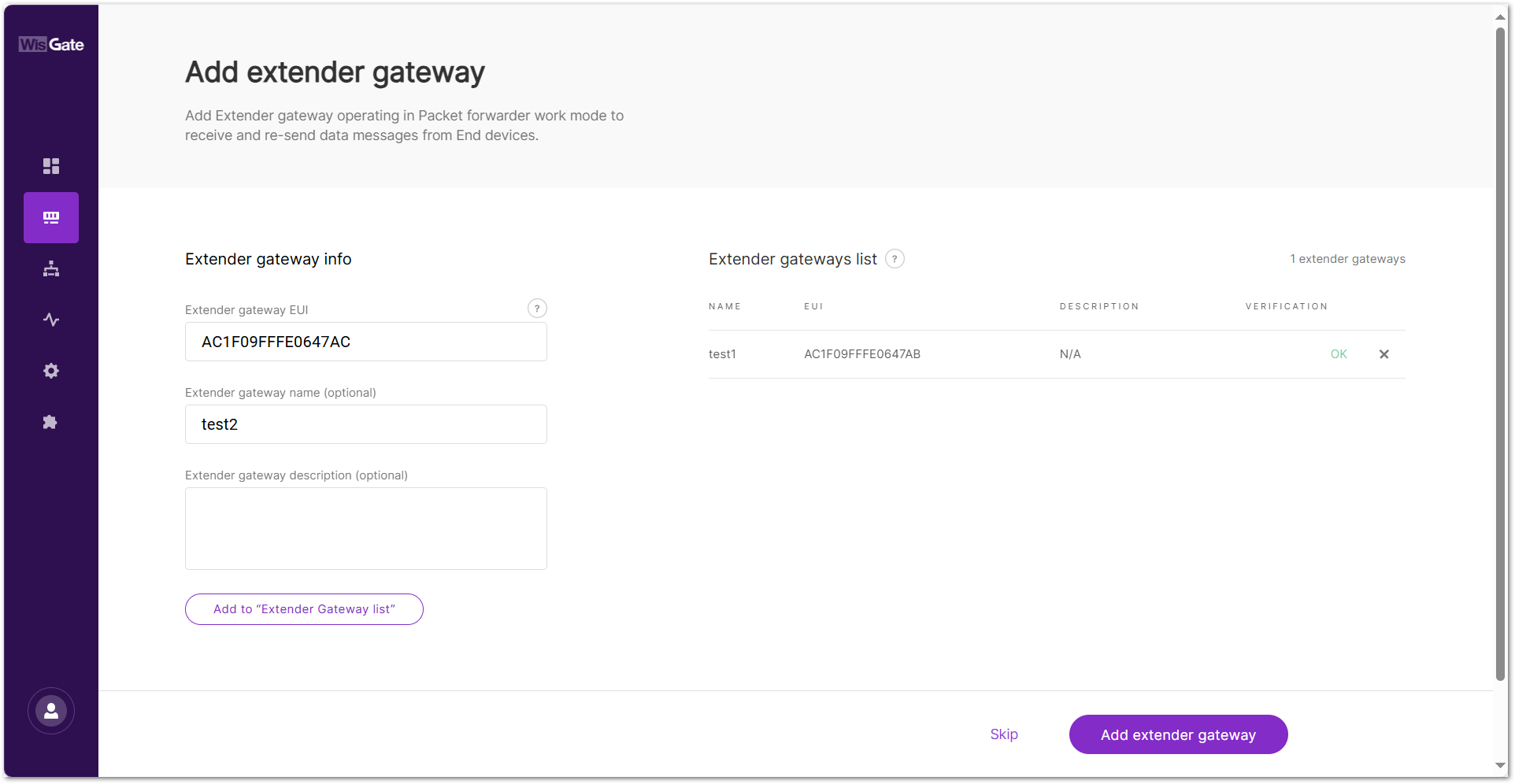 Figure 1: Add gateway
- Extender gateway EUI: Enter the gateway's EUI (Extended Unique Identifier).
- Extender gateway name (optional): Name of the gateway.
- Extender gateway description (optional): A description of the gateway.
-
To save the changes, click the Add to "Extender Gateway list". The extender gateway will now appear in the Extender Gateway list.
NOTEYou can also click the X icon to delete the extender gateway.
-
Click Add extender gateway to add an extender gateway to the Built-in Network server.
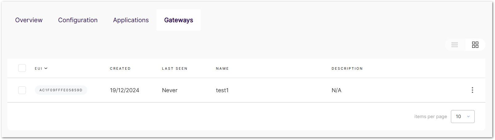 Figure 1: Added gateway
- Adding an extender gateway here only registers it on the central gateway.
- To enable full LoRa packet forwarding functionality, each extender gateway must be properly configured to connect to the central gateway using either the UDP or MQTT protocols. For detailed configuration steps, refer to the following guide:
Manage Extender Gateways
View/Modify Extender Gateway Settings
- Navigate to LoRa > Gateways. View all added extender gateways in this panel.
- Click the target extender gateway, or click () and choose View gateway details.
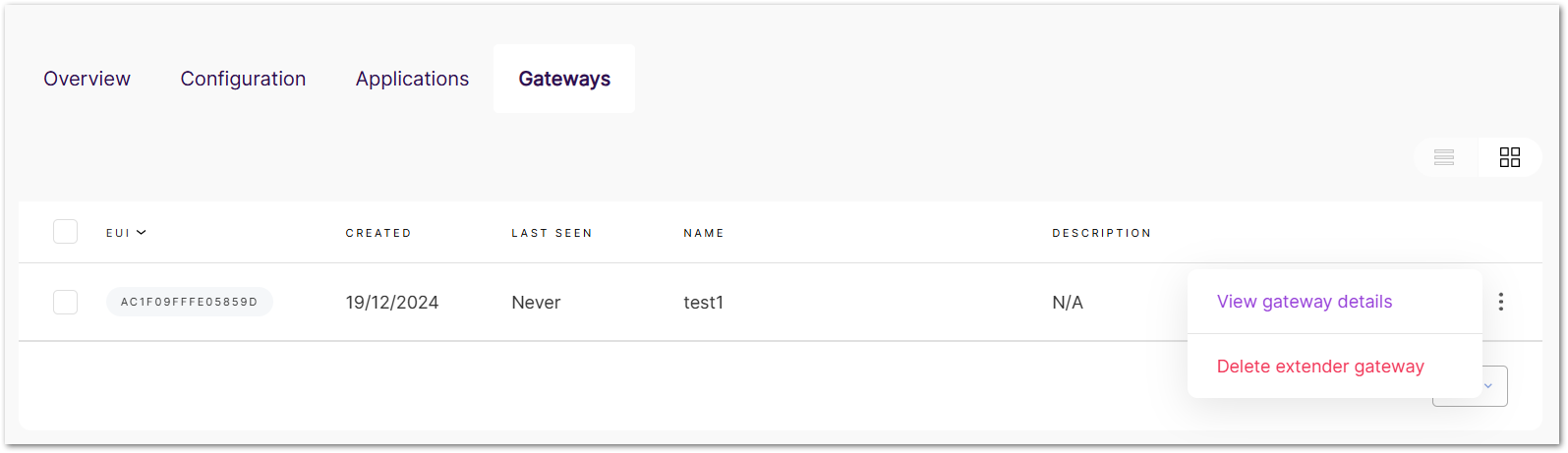 Figure 1: View or delete the gateway
- In the details tab, you can view and modify the extender settings.
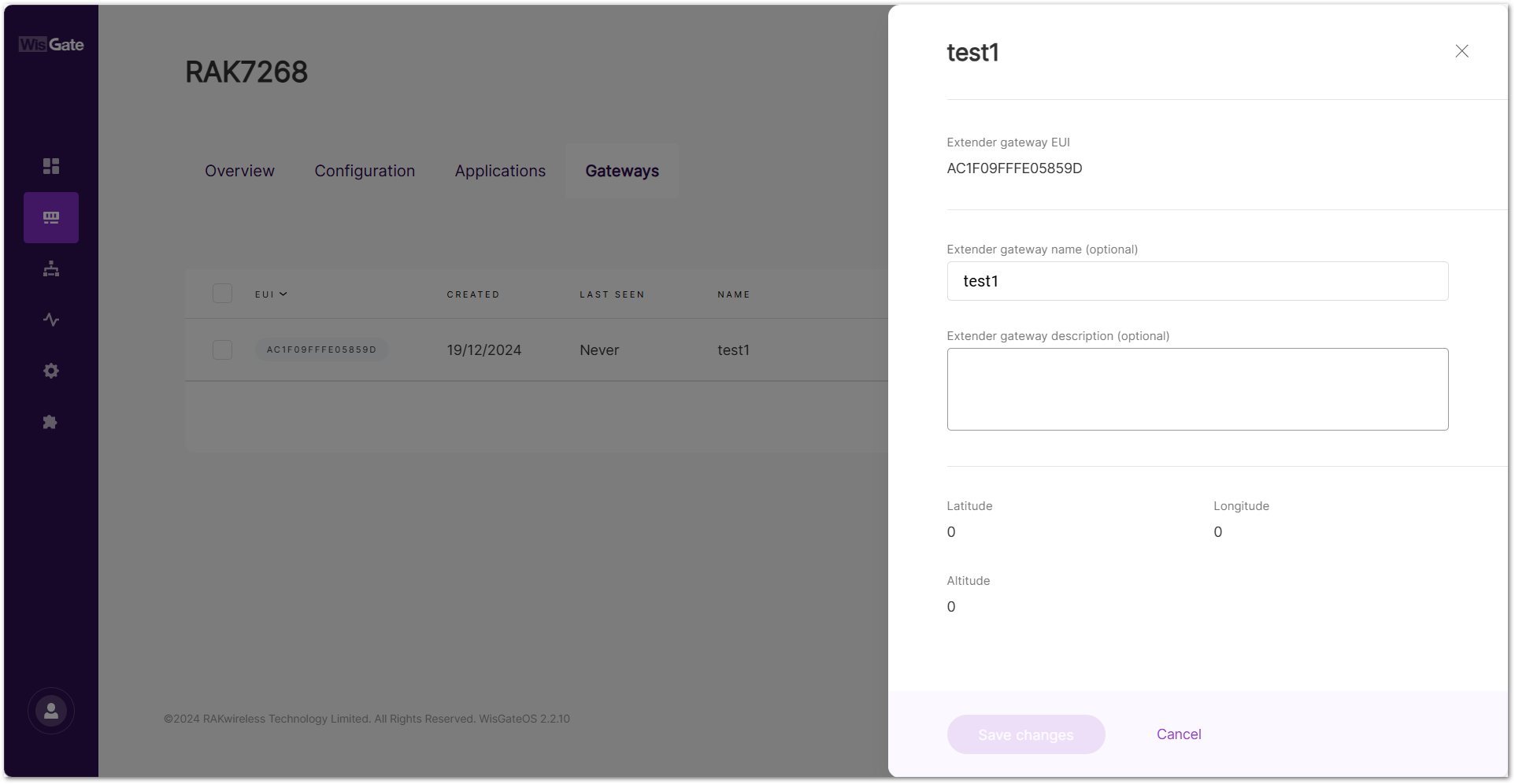 Figure 1: Extender gateway details
Delete Extender Gateway
Once deleted, the extender gateways cannot be recovered. Proceed with caution.
- Delete a Single Extender Gateway
- Navigate to LoRa > Gateways.
- In the target extender gateway's information section, click () and choose Delete extender gateway.
- Batch Delete Applications
- Go to LoRa > Gateways.
- Select checkbox(es) for target extender gateway(s).
- Click Delete.
Overview
The Overview tab provides a real-time summary of the traffic and connected end devices for both the central gateway and any extender gateways. This tab is available only when the gateway is set to Built-in Network Server mode.
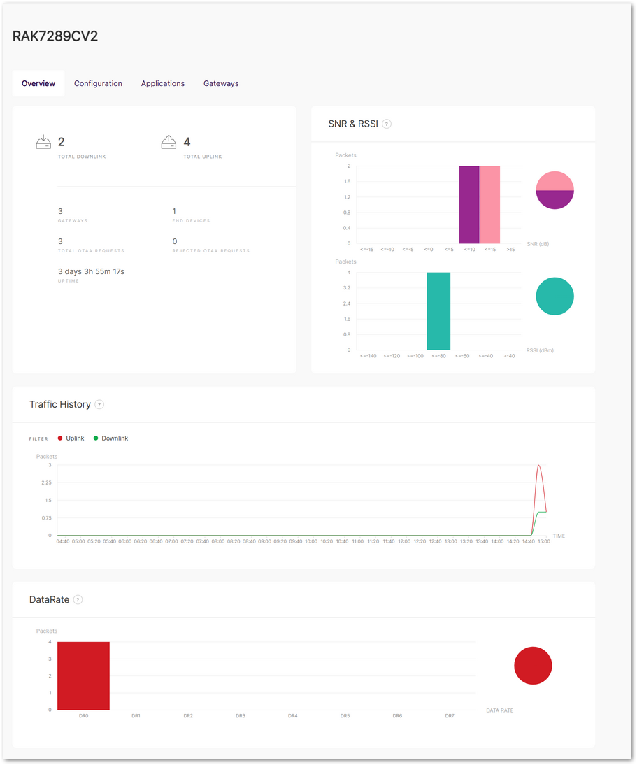 Figure 1: Overview
General Status
Displays key status information for the central gateway and extender gateways:
- Total Downlink: Total number of downlink frames transmitted.
- Total Uplink: Total number of uplink frames transmitted.
- Gateways: Total number of extender gateways connected to the built-in server, including the central gateway.
- End Devices: Total number of authenticated end devices connected to the server.
- Total OTAA Requests: Total number of authentication requests from end devices.
- Rejected OTAA Requests: Total number of authentication requests rejected by the server.
- Uptime: Total time the built-in server has been running without interruption.
SNR & RSSI
Displays the Signal-to-Noise Ratio (SNR) and Received Signal Strength Indicator (RSSI) values graphically.
Traffic History
Provides a graph showing the number of packets transmitted over time.
DataRate
Displays the number of packets transmitted at each data rate (DR0 to DR7).
Packet Forwarder
When configuring Packet Forwarder mode, you can choose between two protocols:
Semtech UDP GWMP Protocol
- The Semtech UDP Packet Forwarder is the traditional and widely used protocol for LoRaWAN gateways.
- The gateway sends uplinks as raw UDP packets to the LNS (LoRaWAN Network Server) and receives downlinks via UDP.
LoRa Gateway MQTT Bridge
- The MQTT-based Packet Forwarder allows LoRaWAN traffic to be encapsulated in MQTT messages instead of raw UDP packets.
- Provides better security than UDP by supporting TLS encryption and authentication.
Configuration
This section explains how to configure the gateway in Packet Forwarder mode.
Set Work Mode to Packet Forwarder
Set the gateway into Packet Forwarder mode so it can forward LoRa packets to an external LNS.
 Figure 1: Work mode
Set Log Level
Configure the log level for debugging and monitoring purposes.
Figure 1: Log Level- Error: Logs of error conditions.
- Warning: Logs of warning conditions.
- Notice: Logs of significant but normal events.
- Info: Logs of general system activity and information.
- Debug: Logs of all messages, including detailed debugging information.
Select Your Country & Region
Figure 1: Select your country & regionSelect your country(Optional)
Selecting the correct country ensures that the gateway operates in compliance with local regulations. The gateway's transmit power will be set to the maximum allowed by local regulations, and the LBT (Listen Before Talk) feature will be enabled if required.
- Click Select your country.
- From the dropdown list, select the Country where the gateway will be deployed.
- Select the appropriate Region.
- Check the confirmation box to acknowledge compliance with local regulations.
- Click Confirm to save your settings.
Figure 1: Country code settingsRegion
Set the region here. The frequency plan can be switched for the following regions:
- US915, AS923, KR920, AS923
- EU868, RU864, IN865
- EU433
- CN470
- If you have already configured the Region in the Select your country settings, it will be automatically applied to the Region configuration.
- Different hardware supports different LoRaWAN regions.
- If your Region is set to AS923, you need to configure the Variation option, such as AS923-1/AS923-2/AS923-3/AS923-4.
Detailed Regional Frequency Settings
This section allows you to fine-tune sub-bands, LoRa/FSK channels, and network mode according to your deployment needs.
Click View detailed regional parameters of the frequency plan in the Frequency Plan section to expand and access advanced configuration options.
When Conform to LoRaWAN is Enabled
The gateway follows the LoRaWAN protocol and the regional frequency plan. You can adjust frequency settings within the LoRaWAN standard.
The frequency settings vary by region due to different radio regulations and frequency allocations. This affects the available channel types and the UI display.
- Frequency Sub-Band: Select the specific frequency sub-band based on the region's frequency plan.
Figure 1: Frequency Sub-Band Selection- Multi-SF LoRa Channel Frequency (MHz): Set the frequency for the Multi-SF LoRa channel.
- Standard LoRa Channel Frequency (MHz): Set the frequency for the standard LoRa channel.
- FSK Channel Frequency (MHz): Set the frequency for the FSK channel.
Figure 1: Frequency settingsWhen Conform to LoRaWAN is Disabled
The gateway will not follow the LoRaWAN frequency plan, allowing private channel plans. You configure each LoRa concentrator manually.
-
Toggle Conform to LoRaWAN to OFF and Confirm when prompted.
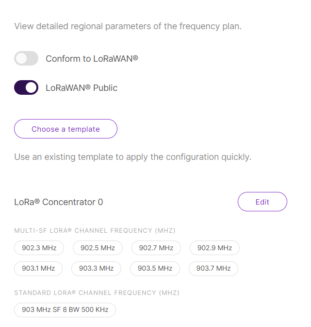 Figure 1: Go to set private channels
 -
Click Edit under per LoRa concentrator.
-
Manually configure the frequencies based on your server's plan.
 Figure 1: Set your LoRa concentrator
 -
Click Confirm to apply channel configuration.
To quickly populate channel settings, click Choose a template instead of manual configuration.
LoRaWAN Public
When enabled (by default), the gateway will process data from all end devices. If you want to create a private network, you can turn it off. The gateway will process the data only from the end devices, whose sync word is changed to private.
Configure UDP Protocol Parameters
The Semtech UDP GWMP protocol allows the gateway to communicate with an LNS (LoRa Network Server) using the UDP packet forwarder. Follow these steps to set it up:
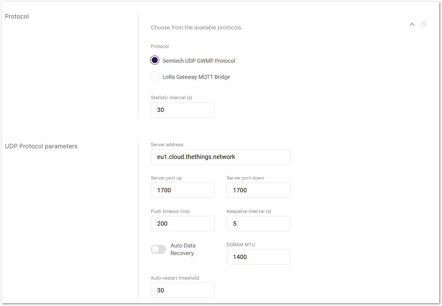 Figure 1: UDP Protocol Parameters
- Go to the Protocol settings in Packet Forwarder mode.
- From the protocol list, choose Semtech UDP GWMP Protocol.
- Set status report interval.
- Static Interval (s): Defines the interval (in seconds) at which the gateway sends status reports containing operational and packet processing statistics.
- Configure LNS connection:
- Server address: Enter the IP address or domain name of your LNS.
- Server port up/down: Enter the ports for uplink and downlink communication.
- Push timeout (ms): Set the maximum wait time for an LNS response after sending uplink data.
- Keepalive interval (s): Set how often the gateway sends keepalive messages to verify connectivity.
- Enable Auto Data Recovery (Optional).
- Turn on Auto Data Recovery to store LoRa frames on the SD card when disconnected.
- Once reconnected, all buffered messages will be automatically forwarded until the buffer is cleared.
- Adjust advanced settings (Optional).
- DGRAM MTU: The maximum transmission unit size (default: 1400).
- Auto-restart threshold: Defines the number of missed keepalive intervals before restarting the Packet Forwarder.
Configure LoRa Gateway MQTT Bridge
The LoRa Gateway MQTT Bridge allows the gateway to communicate with an LNS (LoRa Network Server) using the MQTT protocol. Follow these steps to set it up:
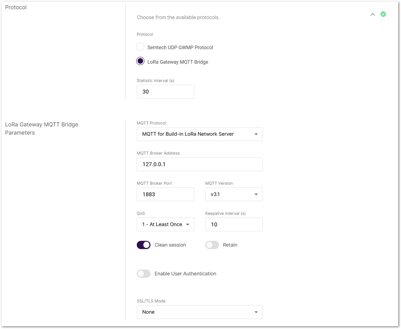 Figure 1: LoRa Gateway MQTT Bridge Parameters
- Go to the Protocol settings in Packet Forwarder mode.
- From the protocol list, choose LoRa Gateway MQTT Bridge.
- Set status report interval.
- Static Interval (s): Defines the interval (in seconds) at which the gateway sends status reports containing operational and packet processing statistics.
- Select MQTT bridge protocol:
- MQTT for Built-in LoRa Network Server: This option forwards packets from extender gateways to the central gateway in multi-gateway setups.
- MQTT for ChirpStack 2.x
- MQTT for ChirpStack 3.x (JSON)
- MQTT for ChirpStack 3.x (Protobuf)
- MQTT for ChirpStack 4.x (Protobuf)
- Enter MQTT Broker information.
- MQTT Broker Address: IP address of the MQTT broker.
- MQTT Broker Port: Default 1883.
- MQTT Version: Choose between V3.1 and V3.1.1. There is very little difference between them, more information can be found on GitHub repo.
- Configure message delivery options.
- QoS (Quality of Service):
- 0 - At Most Once
- 1 - At Least Once
- 2 - Exactly Once
- Keepalive interval (s): Interval in seconds to keep the connection alive (default:
10). - Clean Session: When enabled, the broker does not store session data.
- Retain: If enabled, the last published message is retained.
- QoS (Quality of Service):
- Enable authentication (Optional).
- Toggle Enable User Authentication and enter a username and password.
-
Set security options (Optional).
- SSL/TLS Mode: Configure secure connection
- None
- CA signed server certification
- Self-signed server certification
- Self-signed server & client certification
- TLS Version: Choose between TLS v1.1 and TLS v1.2.
- SSL/TLS Mode: Configure secure connection
-
MQTT Topics.
The following topics are predefined by the LNS specification and do not require manual configuration:
- Uplink Topic
- Downlink Topic
- Downlink Acknowledge Topic
- Gateway Statistic Topic
Set Secondary LNS Forwarding
Enable forwarding of uplink packets to a secondary LoRaWAN Network Server (LNS) for uplink-only monitoring purposes. End devices must be in ABP mode. The secondary LNS does not support downlink traffic, and it must not be configured with the same server address and port as the primary LNS.
- Toggle Secondary LNS Forwarding to enable this feature.
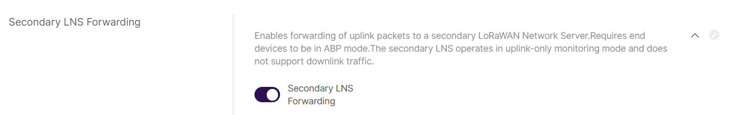 Figure 1: Enable Secondary LNS Forwarding
- Choose the protocol for communication with the Secondary LNS:
- Semtech UDP GWMP Protocol
- LoRa Gateway MQTT Bridge
- Configure the Secondary LNS connection parameters.
-
Semtech UDP GWMP Protocol
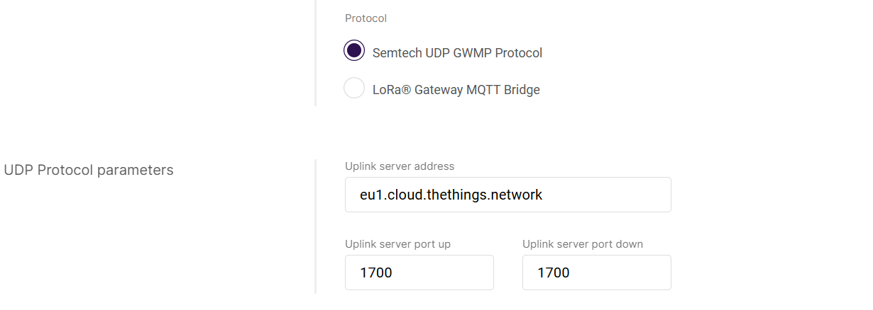 Figure 1: Semtech UDP GWMP Protocol
- Uplink server address: IP address or domain of the Secondary LNS.
- Uplink server port up / down: Port number for the protocol.
-
LoRa Gateway MQTT Bridge
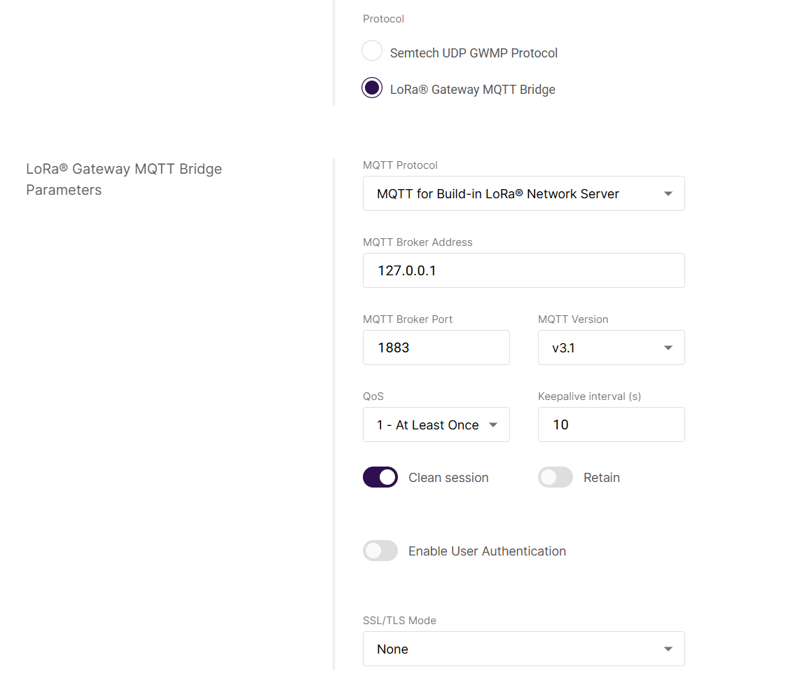 Figure 1: LoRa Gateway MQTT Bridge
The parameters for the secondary LNS follow the same format and meaning as the primary LNS configuration (see Configure LoRa Gateway MQTT Bridge section).
Configure Class B Beaconing
Enable time-synchronized beaconing and set ping slot parameters for Class B end devices. This option is only available on certain gateway models with GPS capability.
To expand the menu, click on Configure the beacon period and ping slots of class B devices to use time-sync beacons sent by the gateways.
Figure 1: Class B Settings- Enable Beacon: The switch enables/disables Class B beaconing.
- Enable Hopping: Enables/disables Class B hopping as the class B beacon is transmitted following a frequency hopping pattern.
- Beacon Frequency (MHz): The frequency of the beacon. If frequency hopping is enabled, this option does not appear.
- Beacon TX Power: This is the transmit power of the beacon ping.
Configure Manual GPS (Fake GPS)
Fake GPS allows manually setting virtual coordinates for gateways in areas without GPS signals, ensuring accurate location data is sent to the LNS.
Click Add your GPS info manually to expand the GPS settings and enable Fake GPS using the switch.
Once enabled, the gateway will use the manually configured GPS coordinates even if it can receive actual GPS signals.
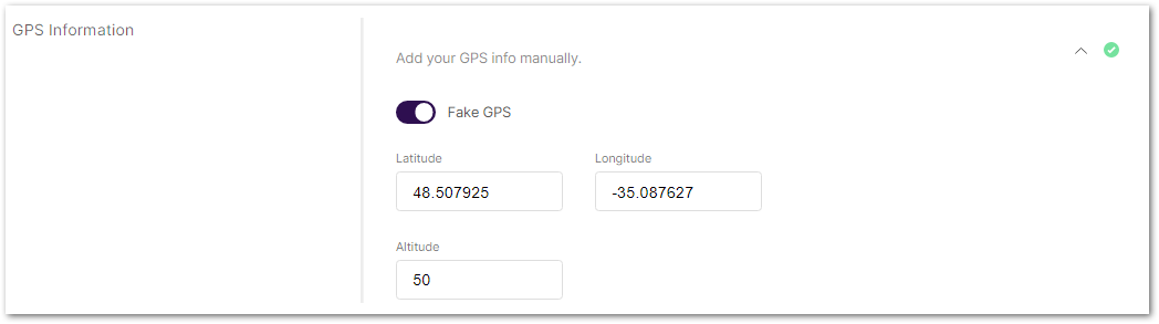 Figure 1: GPS Information
- Latitude: Enter the latitude value.
- Longitude: Enter the longitude value.
- Altitude: Enter the altitude value.
Enable Fine Timestamp
Fine Timestamp enables high‑precision RX timestamps in uplink packets for TDOA positioning, allowing the LNS to calculate device location.
Due to hardware differences, the Fine Timestamp feature is only available on specific RAK gateway models.
Click on Include fine timestamp in uplink packet for TDOA positioning to expand the fine timestamp setting.
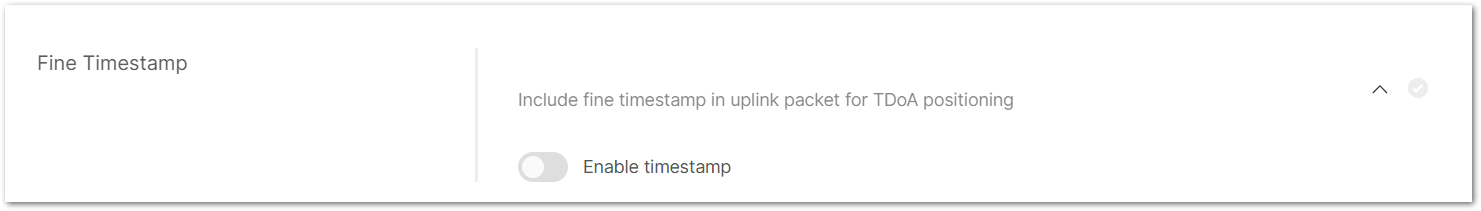 Figure 1: Fine Timestamp
Enable Packet Filter
Set up a packet filter to optimize bandwidth by forwarding packets only from selected devices (disabled by default).
Click Allows to optimize bandwidth by filtering and forwarding packets from chosen end devices to expand packet filter settings.
Figure 1: Packet Filter- White List Mode: Disabled by default. Enable it to allow filtering based on OUI and Network ID.
- OUI: Filters devices based on the first 3 bytes (6 hexadecimal characters) of the DevEUI, which typically identify the device manufacturer.
- Network ID: A number between 0 and 127 (decimal), derived from the first 7 most significant bits (MSB) of a device's DevAddr. For example, a DevAddr starting with 0x26 (00100110 in binary) has the first 7 bits 0010011, which equals decimal 19.
- Auto Filter: Automatically adds trusted devices to the whitelist based on Join request behavior, without requiring manual configuration.
- Discard Period (s): Shows the time end devices will remain discarded (in seconds).
- Join Period (s): Shows the time after which end devices can send join requests again (in seconds).
- Join Interval (s): Shows the time limit between two consecutive join requests from the same end device (in seconds).
- Join Count 1: Shows the maximum join requests from the same end device during the join interval.
- Join Count 2: Shows the maximum join requests from the same end device during the join period.
LoRaWAN Network Server Guides
In Packet Forwarder mode, the gateway can connect to various LoRaWAN Network Servers using the Semtech UDP or MQTT protocols. The following guides provide step-by-step instructions for different platforms:
Semtech UDP GWMP Protocol
The Things Network (TTN v3)
To connect your gateway to TTN v3 via Semtech UDP, follow the How to Connect RAK Gateways to TTN v3 via UDP guide.
ChirpStack v4
To connect your gateway to ChirpStack v4 via Semtech UDP, follow the How to Connect RAK Gateways to ChirpStack v4 via UDP guide.
LoRa Gateway MQTT Bridge
ChirpStack v4
To connect your gateway to ChirpStack v4 using the LoRa Gateway MQTT Bridge, follow the How to Connect RAK Gateways to ChirpStack v4 via MQTT guide.
Basics Station
Basics Station is a modern communication protocol that ensures secure and stable communication between your LoRaWAN gateway and the network server via WebSockets. It allows the gateway to dynamically connect to various cloud-based LoRaWAN network servers while maintaining high security.
Starting from WisGateOS v2.2.14, RAK gateways now support full 16-channel operation in Basics Station mode. This enhancement enables gateways with a 16-channel concentrator to make full use of all available channels, provided that the connected LoRaWAN Network Server (LNS) also supports 16-channel configurations. To benefit from this capability, both the gateway and the LNS must be properly configured and compatible with extended channel plans.
When configuring Basics Station mode, you can select from the following server types:
CUPS-BOOT Server
- Acts as an initial connection point for the gateway.
- Retrieves the actual CUPS Server details, including its URL, port, and authentication settings.
CUPS Server
- Automates the gateway's configuration for connecting to the correct LNS Server.
- The gateway periodically contacts the CUPS Server to receive updates on LNS settings, security credentials, and connection parameters.
LNS Server
- The gateway directly connects to a LoRaWAN Network Server (LNS) without using CUPS for configuration.
- Requires manual setup of the LNS URL, port, and authentication settings.
Configuration
This section explains how to configure the gateway in Basics Station mode.
Set Work Mode to Basics Station
Switch the gateway to Basics Station mode for secure and stable LoRaWAN communication via WebSockets.
 Figure 1: Work mode
Set Log Level
Configure the log level for debugging and monitoring purposes.
Figure 1: Log Level- Error: Logs of error conditions.
- Warning: Logs of warning conditions.
- Notice: Logs of significant but normal events.
- Info: Logs of general system activity and information.
- Debug: Logs of all messages, including detailed debugging information.
Configure Basics Station Server
Click on Configure Basics Station server setup to expand the Basics Station server setup menu.
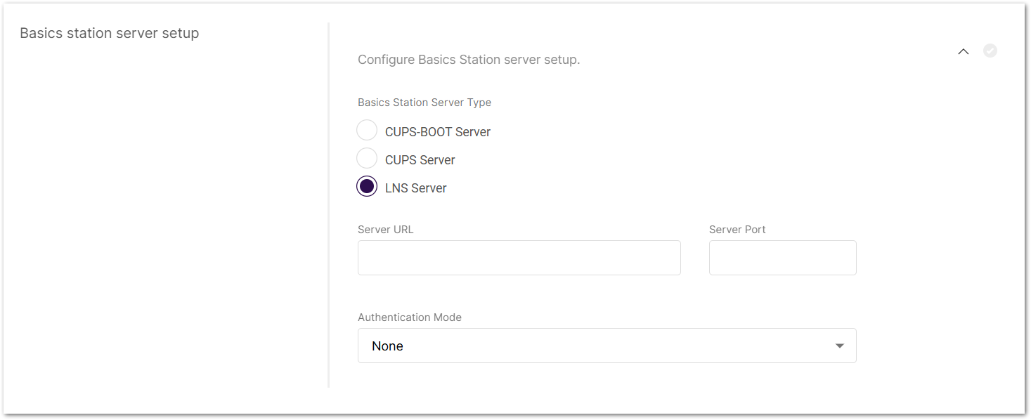 Figure 1: Basics Station server setup
- Basics Station Server Type: When configuring Basics Station mode, you can select from the following server types.
- CUPS-BOOT Server
- CUPS Server
- LNS Server
- Server URL: Enter the URL of the server that the gateway will connect to.
- Server Port: Enter the server's port number.
- Authentication Mode: Choose the appropriate authentication mode based on your server's requirements.
- No Authentication: The server does not require authentication.
- TLS Server Authentication: The server requires a trust file for authentication.
- TLS Server and Client Authentication: The server requires a trust file, certificate, and key files for authentication.
- TLS Server Authentication and Client Token: The server requires a trust file and a client token.
- Trust (CA Certificate): A file that contains the root certificate authority (CA) used to verify the server's identity.
- Client certificate: A digital certificate used to identify the client (gateway) to the server.
- Client key: A private key used in combination with the certificate for mutual TLS authentication.
- Client Token: A unique identifier used to authenticate the client without using certificates.
Enable Packet Filter
Set up a packet filter to optimize bandwidth by forwarding packets only from selected devices (disabled by default).
Click Allows to optimize bandwidth by filtering and forwarding packets from chosen end devices to expand packet filter settings.
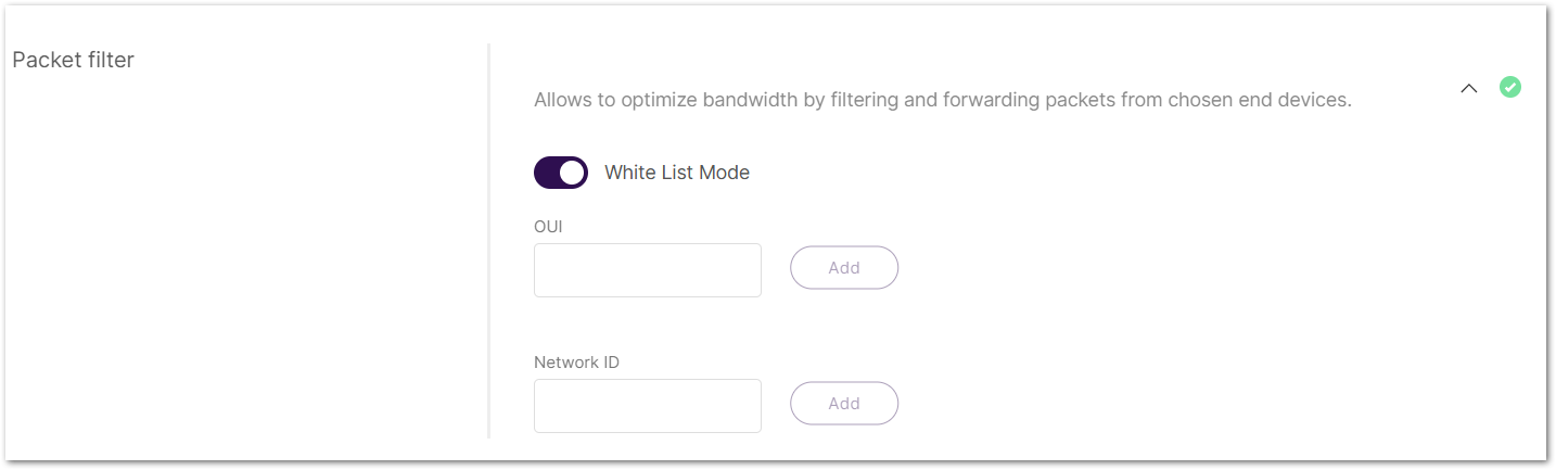 Figure 1: Packet Filter
- White List Mode: Disabled by default. When enabled, it filters devices based on their OUI and Network ID.
- OUI: Filters devices based on the first 3 bytes (6 hexadecimal characters) of the DevEUI, which typically identify the device manufacturer.
- Network ID: A 6-character hexadecimal value. Refer to NetID and DevAddr Prefix Assignments table to determine the network.
LoRaWAN Network Server Guides
In Basics Station mode, the gateway can connect to LNS servers directly or via CUPS provisioning. The following guides explain how to configure your gateway for each supported platform:
LNS Server
The Things Network (TTN v3)
To connect your gateway to TTN v3 using Basics Station LNS, follow the How to Connect RAK Gateways to TTN v3 Using Basics Station (LNS) guide.
CUPS Server
The Things Network (TTN v3)
To connect your gateway to TTN v3 using Basics Station CUPS, follow the How to Connect RAK Gateways to TTN v3 Using Basics Station (CUPS) guide.
Actility ThingPark
To connect your gateway to the Actility ThingPark platform using Basics Station CUPS, follow the How to Connect RAK Gateways to Actility via Basics Station (CUPS) guide.: