IO.Box Quick Start Guide
IO.Box is a software application designed for the easy configuration of WisNode Bridge devices, specifically the RAK2470 and the RAK246X series devices.
Download IO.BOX
This application is available for:
Connect to Device
Prerequisite
-
The WisNode Bridge is powered on and operating normally.
-
The RS485, DI/DO, or AI/AO interfaces are correctly connected to the corresponding Bridge IO ports.
Connect Automatically/Manually
- To configure the application, connect the device to the computer using the provided USB cable.
- Start the IO.Box and click Connect Device.
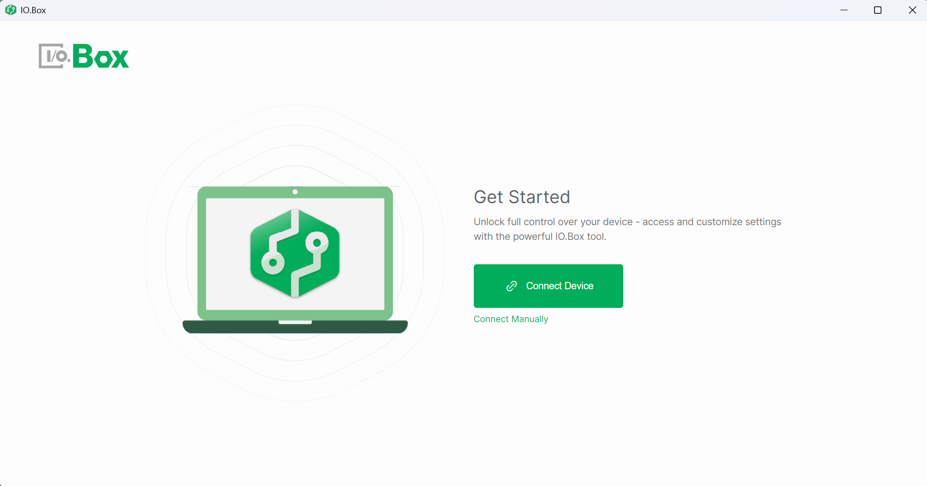 Figure 1: Start the IO.Box
- After clicking Connect Device, the device will be automatically detected, and the LoRaWAN Configuration tab will appear.
- If the device is not automatically detected, click Connect Manually and follow the instructions to add it.
- After the device is connected, ensure the connected device is powered on. If it requires external power from the IO.Box, go to the System tab and enable the corresponding output under Power Output.
- The main menu on the left will differ depending on the device you are configuring.
LoRaWAN
By configuring the following LoRaWAN parameters, you can connect your devices to a LoRaWAN network and manage communication parameters. After configuring the settings, click Save to apply the changes and activate the configuration on your device.
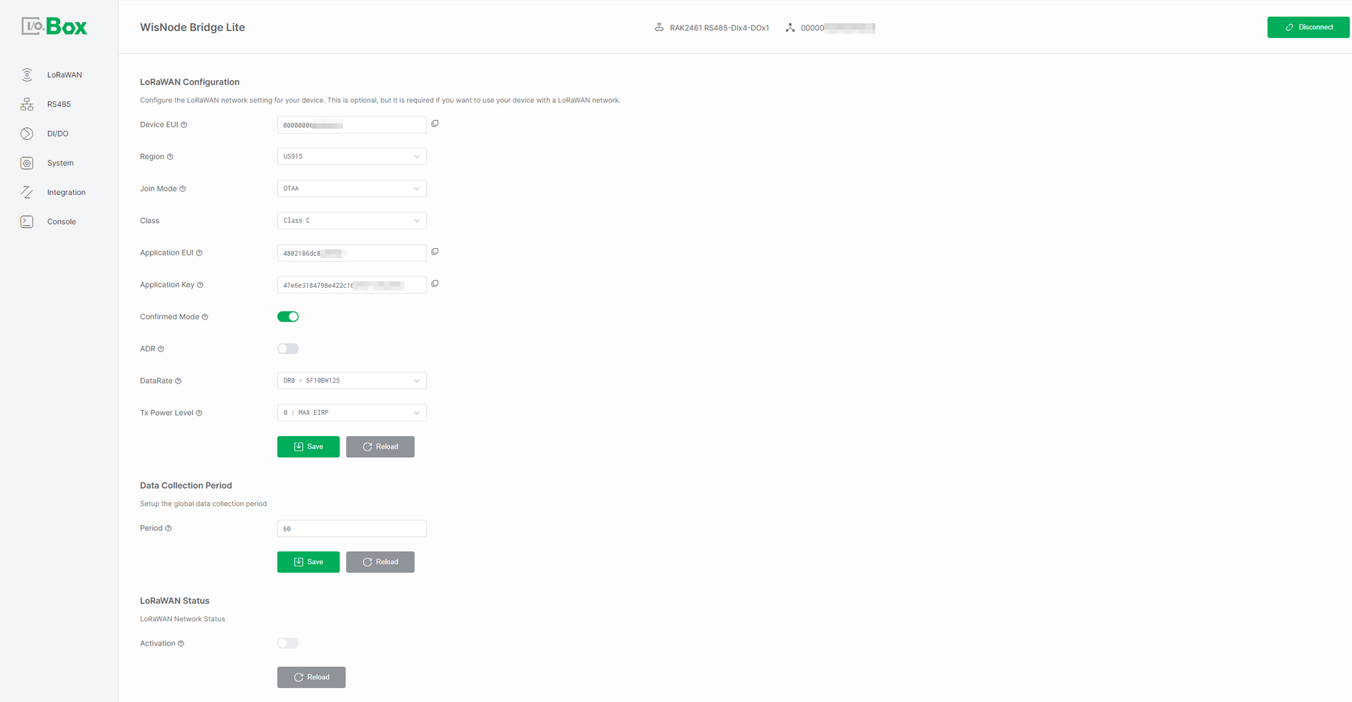 Figure 1: LoRaWAN tab
LoRaWAN Configuration
In the LoRaWAN Configuration section, you can set various parameters required to connect your device to the LoRaWAN network.
- Device EUI - The unique identifier of the device. This cannot be modified.
- Region - The LoRaWAN frequency band used by the device.
- Join Mode - The mode used for device network joining. Select either OTAA or ABP depending on your device joining method.
- Over-The-Air Activation (OTAA)
- Activation By Personalization (ABP)
- Class - The type of LoRaWAN communication used by the device.
- Application EUI - The application identifier for the device. Ensure it matches the Application EUI configured in the LoRa network server.
- Application Key - The security key for device-server encryption and authentication. Ensure it matches the Application key in the LoRa network server.
- Confirm Mode - Message acknowledgment mode. When enabled, the network server will acknowledge the uplink data. If no acknowledgment is received, the device will resend the data. If disabled, the network server will not send an acknowledgment.
- ADR - When enabled, the network server dynamically adjusts the data rate (DR) and transmission power based on the gateway’s signal strength (SNR) and coverage. If disabled, the device can manually configure the data rate and power based on the following parameters:
- DataRate: It can be configured when ADR is disabled. Lowering the data rate increases range but also adds communication time and power consumption. Choose based on the device-gateway distance and signal quality.
- Tx Power Level: It can be configured when ADR is disabled. A smaller transmission power value represents higher power. 0 is the maximum allowed power, with each increment reducing power by approximately 2 dBm.
Data Collection Period
The Data Collection Period determines how often the device uploads data to the LoRaWAN network server.
- Period- Set up the data collection period (polling period) of the device.
- Range: 60~86400 seconds
Check LoRaWAN Status
- LoRaWAN Status - Check the status of the device’s connection to the LoRaWAN network. After a successful network join, the activation switch will be turned on and cannot be configured.
RS485 Configuration
RS485 is a robust serial communication interface widely used in industrial environments for long-distance, noise-resistant data transmission. In IO.Box, it is used to connect Modbus RTU slave devices (such as power meters, sensors, and PLC I/O modules) for periodic data collection and remote control through polling tasks.
RS485 Interface Configuration
RS485 interface configuration defines the physical-layer serial parameters used between IO.Box and a Modbus RTU device. In the RS485 Interface Configuration menu, you can configure these parameters to match the RS485 communication settings of the connected device. The configuration takes effect after clicking Save.
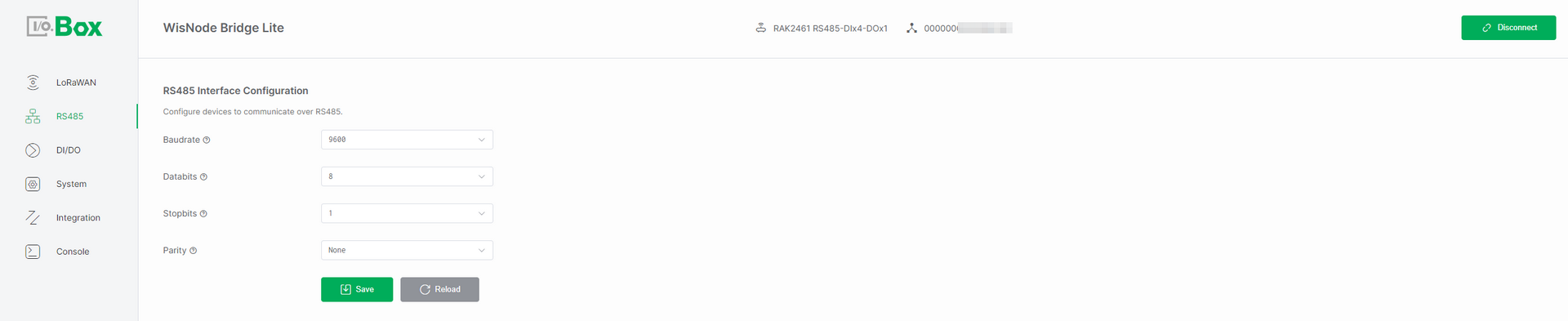 Figure 1: RS485 tab
-
Baudrate: The communication speed on the RS485 bus, measured in bits per second (bps). Select a baudrate that matches the speed required by your connected device.
-
Databits: The number of data bits in each character. Choose either 7 or 8 bits based on the protocol requirements specified by your device.
-
Stopbits: The number of bits that signal the end of a character frame. Configure this as 1 or 2 stop bits, depending on your device's data transmission protocol.
-
Parity: An error-checking method for serial communication. Select the parity setting that matches your device's requirements from the available options:
-
None (no parity check)
-
Even (even parity check)
-
Odd (odd parity check)
-
Modbus Poll Task
Modbus Poll Task configuration is used to manage Modbus communication. Once enabled, IO.Box can automatically read sensor data or write control commands, making it suitable for industrial automation, data acquisition, and device monitoring scenarios.
Add Modbus Poll Task
In the Modbus Poll Task menu, click + Add to create a new polling task. Configure the parameters below according to the datasheet/manual of the connected device. After setting them up, click Save to activate the task.
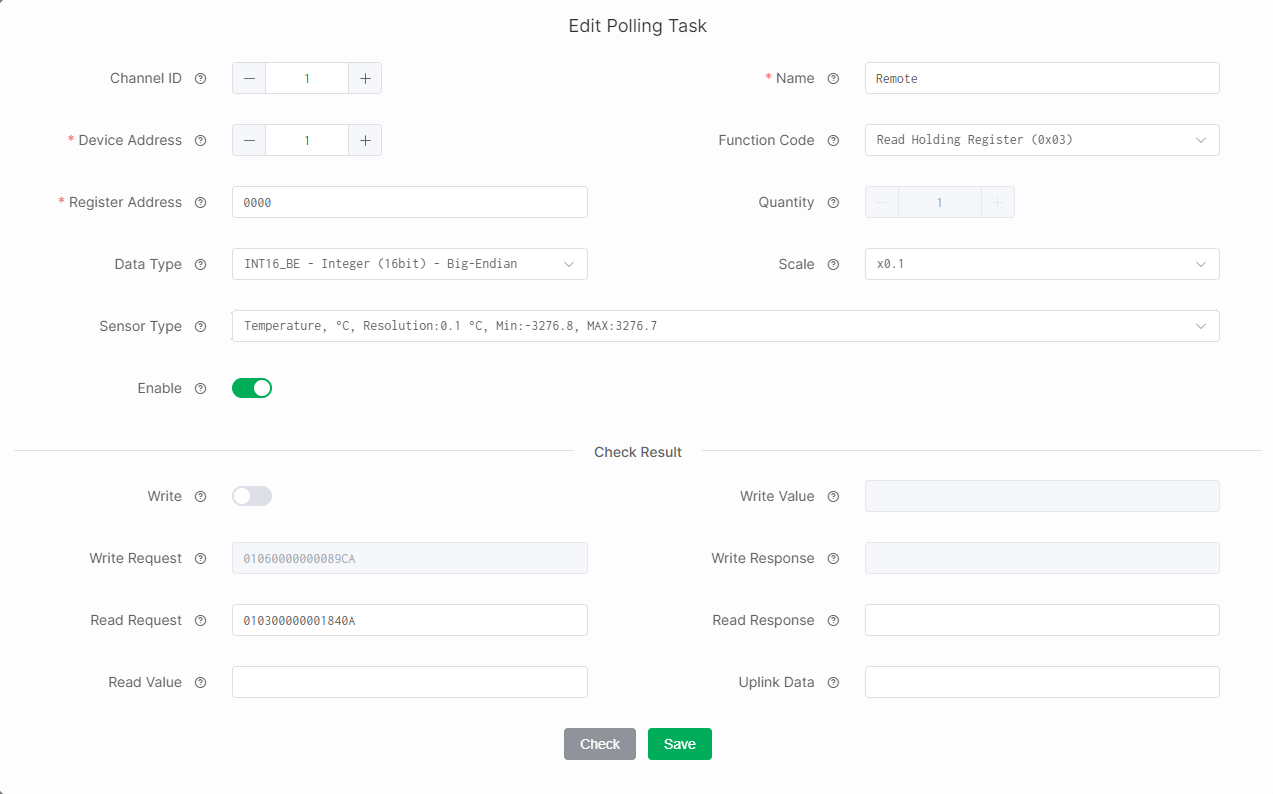 Figure 1: Poll Task1
-
Channel ID: Manually assigned by the user to distinguish different data streams or communication channels. This ID is included in the device’s uplink data to indicate the task.
-
Name: Custom name, length: 4-15.
-
Device Address: The unique address of the connected device on the RS485 bus, obtained from the device manual. If the manual provides the value in hexadecimal, convert it to decimal before entering. Range: 1–254.
-
Function Code: Specifies the task's Modbus operation type (read/write), obtained from the device manual. Common function codes:
-
Read Holding Register (0x03): Read/write configurable parameters (setpoints, thresholds).
-
Read Input Register (0x04): Read real-time measurements (sensor readings), read-only.
-
Read Coil (0x01): Read digital output states (relay/switch), readable and writable.
-
Read Discrete Input (0x02): Read digital input states (switch/alarm), read-only.
-
-
Register Address: The target register/coil address (Internal data storage location) used in the Modbus request, obtained from the device manual. Input format: hexadecimal (for example,
0x0009).NOTERegister Address uses 0-based addressing (offset starts from 0). If your device manual uses logical addresses such as
4xxxx, calculate the decimal offset first, then convert to hex.
Example: device manual shows40010.-
Decimal offset =
40010 - 40001 = 9. -
Register address (hex) =
0x0009(or0009).
-
-
Quantity: The number of registers/coils to read or write. This value depends on the selected Data Type. Refer to Table 1 for details.
-
Data Type: Defines how IO.Box parses the Modbus response payload into a usable value. The value corresponds to the selected registers/coils Quantity. Refer to Table 1 below for the specific mapping.
Table 1. Data Type vs. Quantity Correspondence Table
This table follows the common Modbus convention: one register = 16 bits (2 bytes). Always confirm with your device manual if it uses special packing.
Data Type Data Size Quantity (Registers) Notes INT16 / UINT16 16-bit 1 Signed/unsigned 16-bit integer (Big-Endian or Little-Endian) INT32 / UINT32 32-bit 2 Signed/unsigned 32-bit integer (Big-Endian, Little-Endian, or Mixed) Float 32-bit 2 IEEE 754 float (Big-Endian, Little-Endian, or Mixed) Bit Values varies Manually configurable One register/byte parsed as bit fields (implementation-dependent) Modbus ADU (raw) varies Manually configurable Raw frame parsing, quantity depends on what you need to capture -
Scale: To adjust the raw data from the Modbus response to the desired units. For example, to convert kilograms to grams set the scale to X1000.
-
Sensor Type: Select the unit/category that best matches your slave device output (used for correct interpretation and presentation).
-
Interval: How often the device sends the Modbus request (polling period).
-
Enable: Enable/disable the task. When disabled, IO.Box will not collect data or write values for this task.
Check Result
After you finish editing a poll task, click Check to validate whether:
-
The configuration parameters are correct.
-
The device can communicate successfully, and the response can be parsed into the expected value and uplink payload format.
If there are no issues during the check, click Save to save the configuration.
-
Write: Enables writing to device registers/coils. Configurable when Function Code is Read Holding Register (0x03) or Read Coil (0x01).
-
Write/Read Request: Displays the Modbus command generated from the polling task configuration, based on the selected settings, will be used to communicate with the Modbus device.
-
Write/Read Response: The response returned by the slave for the request, indicates whether the operation succeeded and contains returned data.
-
Write Value: The value written to the specified register/coil.
-
Read Value: The parsed value extracted from the response according to the above configuration.
-
Uplink Data: The formatted payload that IO.Box will send to the server, based on your task configuration.
Edit Modbus Poll Task
To modify an existing Poll Task, go to the Modbus Poll Task menu, select the target Poll Task, click Edit, update the required fields (such as interval, Register Address, Quantity, Data Type, etc.), and then click Save to apply the changes.
Import/Export Poll Task
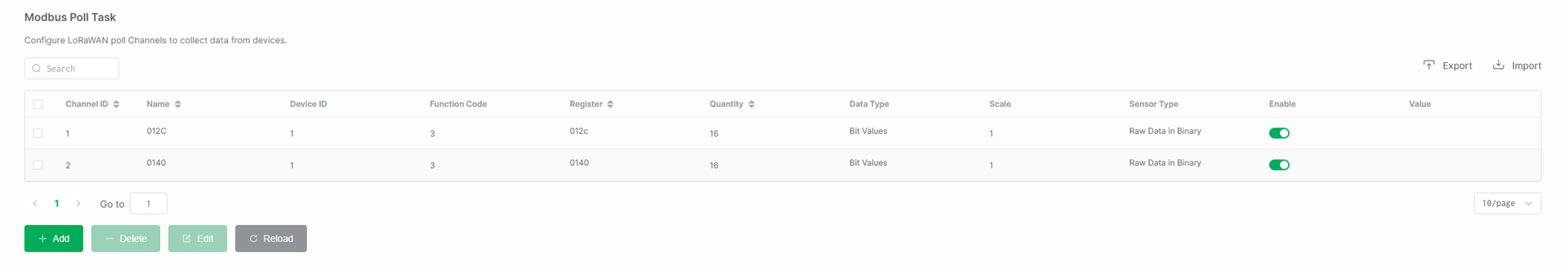 Figure 1: Poll Task2
Import Poll Task
The Import function is used to quickly apply a set of predefined polling tasks to a device, without the need to create them manually one by one. Typical use cases include batch deployment and device replacement.
In the Modbus Poll Task menu, click Import, then select and upload the Modbus Poll Task template file you wish to import.
Export Poll Task
The Export function is used to back up the polling task configuration for later reuse. It is useful for scenarios like saving templates and version management.
In the Modbus Poll Task menu, click Export to download the currently configured Modbus Poll Task to a specified path.
Delete Modbus Poll Task
If you want to delete a polling task, go to the Modbus Poll Task menu, select the target Poll Task, click Delete, and then click OK to remove the task.
After deletion, the device will stop polling those registers, and the corresponding uplink data will no longer be generated for that Channel ID.
DI/DO Configuration
DI/DO interfaces refer to Digital Input and Digital Output interfaces, used for connecting external digital signal devices to enable switch signal acquisition and control. By configuring DI/DO interfaces, users can monitor the switch status of external equipment (DI) or control actuators such as relays and indicator lights (DO).
Digital Input
The Digital Input interface receives external digital signals, such as switch status and sensor trigger signals.
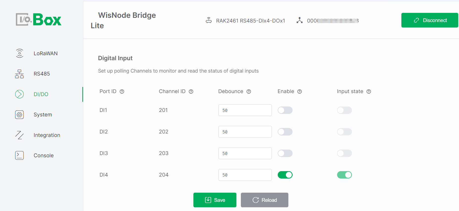 Figure 1: DI/DO tab1
Configuration Steps
-
Navigate to the DI/DO module and select the Digital Input menu.
-
Enable the Enable switch, keep the remaining parameters at default values, then click Save to apply the configuration.
-
Trigger an external input and check if Input State updates.
Parameter Descriptions
-
Port ID: Identifies the physical DI port, corresponding one-to-one with the Bridge I/O hardware interface. Automatically assigned by the system and cannot be modified.
-
Channel ID: Uniquely identifies the input channel within the system for data reporting and logical processing. Automatically assigned by the system and cannot be modified. Used in LoRaWAN or system data frames.
-
Debounce: Prevents false triggering due to mechanical switch bouncing. Sets the signal stabilization time, only signals stable beyond this duration are considered valid inputs. (Unit: milliseconds).
-
Enable: Enable/Disable the channel. Controls whether the input channel participates in polling and data reporting. Monitoring occurs only when enabled. Default: disabled.
-
Input State: Shows the real-time input level status (high/low) of the port. The status updates in real-time when a valid signal is input from the external device. Read-only.
NOTEThis parameter is active only when Enable is ON.
Digital Output
The DO interface outputs digital control signals to external devices, such as controlling relay switching or indicator light states.
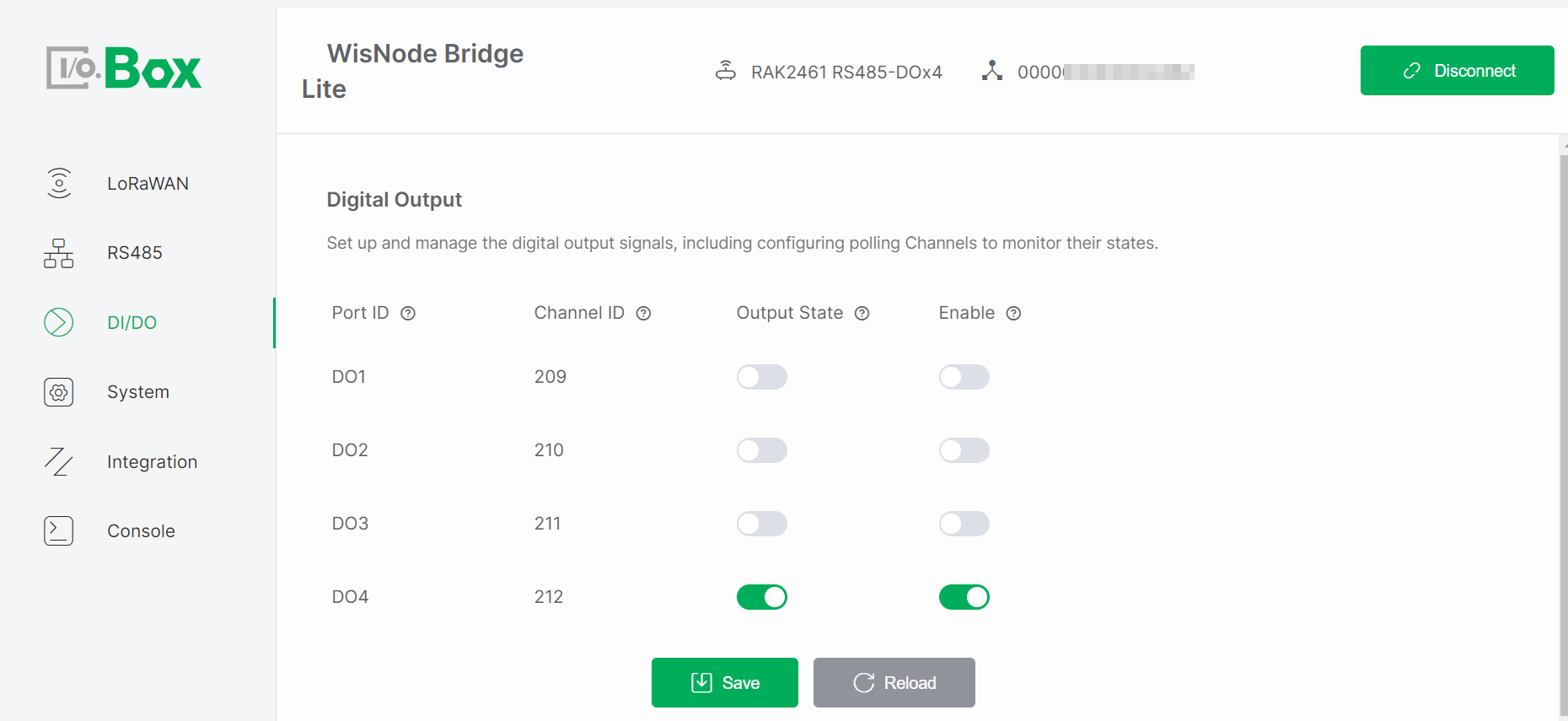 Figure 1: DI/DO tab2
Configuration Steps
-
Navigate to the DI/DO module and select the Digital Output menu.
-
Enable the Enable switch, set the desired Output State, and click Save to apply the configuration.
-
Observe whether the actuator operates as expected.
Parameter Descriptions
-
Port ID: Identifies the physical DO port, corresponding one-to-one with the Bridge I/O hardware interface. Automatically assigned by the system and cannot be modified.
-
Channel ID: Uniquely identifies the output channel within the system for command issuance and status tracking. Automatically assigned by the system and cannot be modified. Used as an address identifier in control commands or data frames.
-
Output State: Controls the output level (high/low) of the port for controlling external devices. The state changes according to system or user commands. Writable parameter. Note: This parameter is active only when Enable is ON.
-
Enable: Enable/Disable the output channel. The Output State takes effect only when enabled. Default: disabled.
AI/AO Configuration
The AI/AO interface provided by the Bridge I/O 2462 includes Analog Input (AI) and Analog Output (AO) channels for handling continuously varying analog signals. By properly configuring the AI/AO interfaces, users can implement industrial process monitoring, environmental data acquisition, and closed-loop analog control.
Analog Input
Analog Input (AI) interfaces are designed to collect continuously varying signals from external sensors, such as temperature, pressure, liquid level, and current transmitters. These signals are converted into digital values for system processing and monitoring.
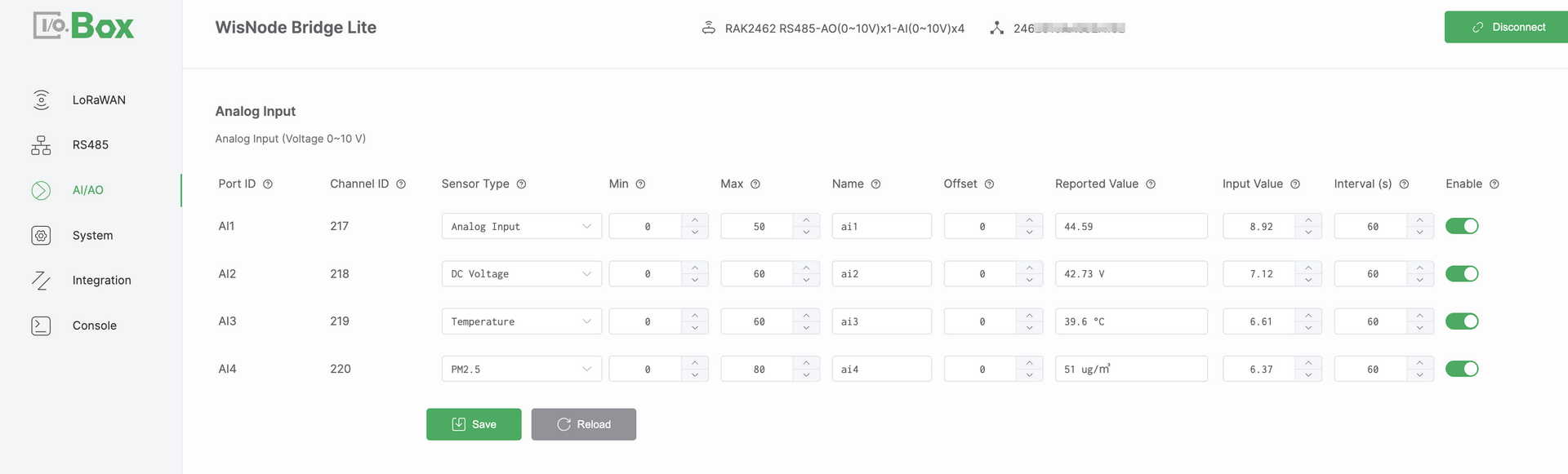 Figure 1: AI/AO tab1
Configuration Steps
-
Navigate to the AI/AO module and select the Analog Input menu.
-
Select the target Port ID and configure the following parameters:
-
Select a Sensor Type (for example,
Temperature). -
Set the Min and Max values (obtained from the Device's specification datasheet), and configure the Offset parameter if required.
-
-
Set Enable to
ON, then click Save to apply the configuration. -
Verify that the Reported Value is displayed correctly and updates as expected.
NOTEIf the Reported Value is not as expected, refer to Analog Input Scaling Logic to verify the mapping formula.
Parameter Descriptions
-
Port ID: Physical AI port identifier, Corresponds one-to-one with the Bridge I/O hardware interface, Automatically assigned and cannot be modified.
-
Channel ID: Unique channel identifier assigned by the system, Used internally for data identification, processing, and uplink reporting, Automatically assigned and cannot be modified.
-
Sensor Type: Defines the semantic type of the connected sensor, Determines how the value is displayed and what it represents.
-
Min: Defines the engineering value corresponding to the lower bound of the input signal, This value is obtained from the Device's specification datasheet.
-
Max: Defines the engineering value corresponding to the upper bound of the input signal. This value is obtained from the Device's specification datasheet.
-
Name: User-defined channel name.
-
Offset: An offset applied to correct numerical values, used to compensate for sensor zero drift or installation deviations.
-
Reported Value: Final engineering value after Min/Max scaling and Offset adjustment, Represents the actual physical quantity.
-
Input Value: Raw analog input value measured by the hardware, Represents the actual electrical signal (current or voltage).
-
Enable: Enables or disables the AI channel, When disabled, the channel does not collect or report data.
Analog Input Scaling Logic
The AI interface supports two analog input specifications: Voltage mode (0–10 V) and Current mode (4–20 mA). Each mode applies a different linear scaling formula to convert the measured Input Value into an engineering value, referred to as the Reported Value.
-
Voltage mode (0–10 V):
Reported Value = (Input Value / 10) × (Max − Min) + Min + Offset -
Current mode (4–20 mA):
Reported Value = ((Input Value − 4) / 16) × (Max − Min) + Min + Offset
This document uses the Voltage mode (0–10 V) as an example:
Assuming Min = 0, Max = 50, Offset = 0, and an input voltage of 8.92 V. The system applies linear scaling to convert the input voltage into an engineering value: Reported Value = (8.92 / 10) × 50 ≈ 44.6.
Analog Output
Analog Output (AO) interfaces are used to generate analog control signals to drive actuators, such as control valves, variable-speed motors, or other industrial equipment.
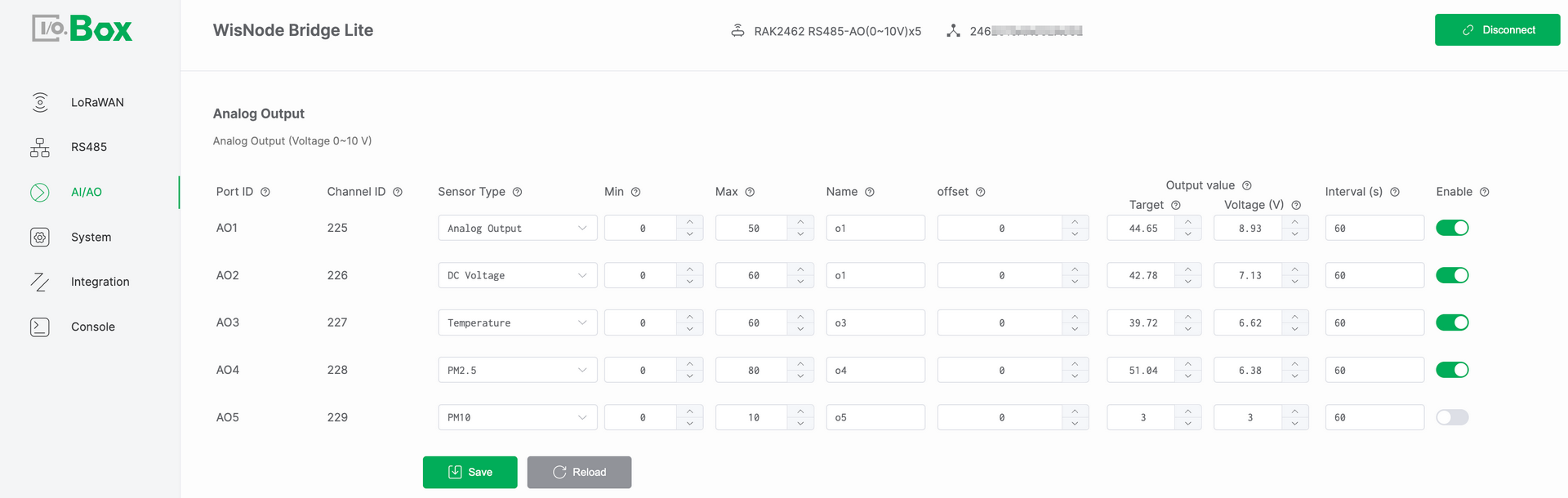 Figure 1: AI/AO tab2
Configuration Steps
-
Navigate to the AI/AO module and select the Analog Output menu.
-
Select the target Port ID and configure the following parameters:
-
Select a Sensor Type (for example,
DC Voltage). -
Set the Min and Max values (obtained from the Device's specification datasheet), and configure the Offset parameter if required.
-
Configure the Target value,Set Enable to
ON.
-
-
Click Save and verify that the output signal (Current (mA) or Voltage (V)) matches the expected value.
NOTEIf the output signal is not as expected, refer to Analog Output Scaling Logic to verify the conversion formula.
Parameter Descriptions
-
Port ID: Physical AO port identifier, Corresponds one-to-one with the Bridge I/O hardware interface, Automatically assigned and cannot be modified.
-
Channel ID: Unique channel identifier assigned by the system, Used internally for data identification, processing, and uplink reporting, Automatically assigned and cannot be modified.
-
Sensor Type: Defines the semantic type of the output signal, Determines how the value is displayed and what it represents.
-
Min: Defines the minimum engineering value of the output range, This value is obtained from the Device's specification datasheet.
-
Max: Defines the maximum engineering value of the output range, This value is obtained from the Device's specification datasheet.
-
Name: User-defined channel name.
-
Offset: An offset applied to correct numerical values, used to compensate for sensor zero drift or installation deviations.
-
Target: User-defined target engineering value set by the user. This value represents the desired control level in engineering terms (for example, a valve opening of 75%) and serves as the input reference for the AO output calculation.
-
Output Value: Derived from the configured Target and serving as the basis for generating the physical analog output signal.
-
Current (mA)/ Voltage (V): The real-time physical analog signal output by the AO port. This value is the electrical representation of the Output Value, expressed as:
-
Current (mA) in 4–20 mA mode
-
Voltage (V) in 0–10 V mode
It reflects the actual internal output data of the device and can be measured directly on the AO interface.
-
-
Enable: Enables or disables the AO channel. When disabled, the channel does not output any signal.
Analog Output Scaling Logic
The AO interface converts the target engineering value into a physical analog output signal using linear scaling. The applied formula depends on the AO hardware output mode. The AO interface supports two analog output specifications:
-
Voltage mode (0–10 V):
Output Voltage (V) = (Target − Min) / (Max − Min) × 10. -
Current mode (4–20 mA):
Output Current (mA) = (Target − Min) / (Max − Min) × 16 + 4.
This document uses the Voltage mode (0–10 V) as an example:
Assuming Min = 0, Max = 50, Offset = 0, and Target = 29. The system converts the target value into an analog voltage output: Output Voltage = (29 / 50) × 10 ≈ 5.8 V.
Integration configuration
Integration Configuration enables Bridge IO devices to seamlessly integrate with mainstream LoRaWAN® Network Servers and efficiently manage Device Profiles. It provides a streamlined workflow to onboard devices, generate payload codecs automatically, and synchronize configurations across multiple devices, significantly reducing deployment and maintenance effort.
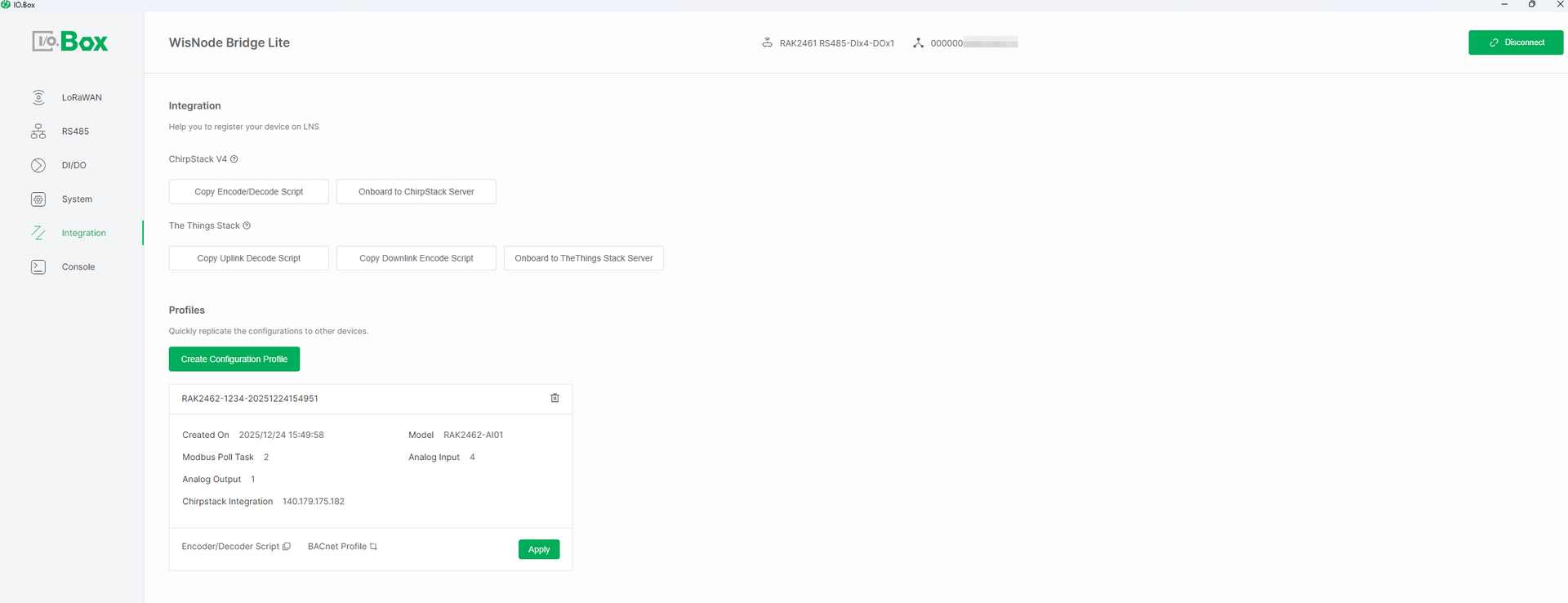 Figure 1: Integration tab1
Integration with LoRaWAN Servers
Integration with LoRaWAN Servers allows Bridge IO to connect devices to external LoRaWAN® Network Servers (LNS). Through the IO.Box tool, you can effortlessly onboard devices to the server and automatically generate the necessary payload codec scripts to ensure proper parsing of uplink and downlink data.
Prerequisites
Before starting integration, ensure the following:
-
Bridge IO is connected to a RAKwireless gateway and sensor data is being received.
-
you have logged into the target LoRaWAN server (ChirpStack or TTN), registered your gateway, and created an Application before starting.
ChirpStack v4 Integration
Copy Encode/Decode Script
This feature generates the JavaScript codec functions required by the ChirpStack server. This script defines how to decode the binary payload from the device into readable sensor values and encode downlink JSON commands back into a binary payload for the device.
Configuration Steps
-
In the Integration module, navigate to the ChirpStack v4 menu and click Copy Encode/Decode Script.
-
Paste the copied script into ChirpStack:
-
Go to the target device's Device Profile.
-
Under the Codec tab, set Payload codec to JavaScript functions.
-
Paste the script into the Codec functions editor and click Submit.
-
After completing the above configuration, you can view the decoded uplink data values in the device's Events tab.
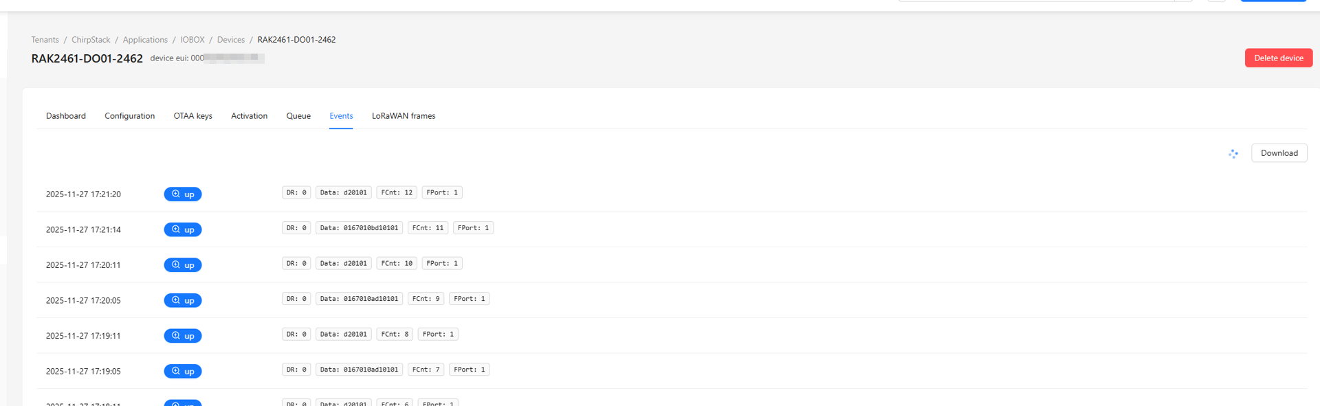 Figure 1: Integration tab2
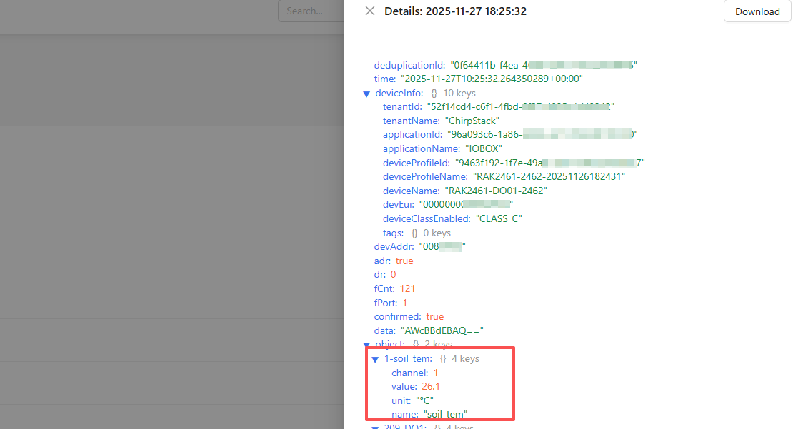 Figure 1: Integration tab3
If the codec script is not configured in the device profile, ChirpStack will be unable to decode device data, leaving only raw hexadecimal payloads visible. Specific decoding errors can be viewed in the corresponding Logs section under the device's Events tab.
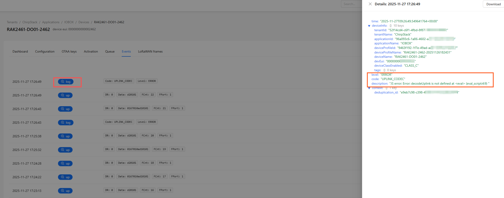 Figure 1: Integration tab4
Onboard to ChirpStack Server
This feature provides a one-click onboarding capability. It automatically registers the current Bridge IO device to a specified application on your ChirpStack server, populating essential device parameters like DevEUI and AppKey.This eliminates manual device creation and reduces configuration errors.
Configuration Steps
-
In the Integration module, navigate to the ChirpStack v4 menu and click Onboard to ChirpStack Server.
-
Select an existing ChirpStack server and click the target Application.
NOTEIf no server is available, click Create New to add one. For detailed steps, refer to Create ChirpStack Server.
-
In the Register End Device to ChirpStack dialog, click Create. The device will then appear automatically under the selected ChirpStack application.
The Things Stack (TTN v3) Integration
Copy Uplink Decode/Downlink Encode Script
This feature generates the JavaScript scripts required for both the TTN server's Uplink payload formatter (to decode device-sent data) and Downlink payload formatter (to encode server commands into a device-readable format).
Configuration Steps
-
In the Integration module, navigate to The Things Stack menu and click Copy Uplink Decode Script or Copy Downlink Encode Script.
-
Paste the copied script(s) into The Things Stack:
-
Select the target device and navigate to Payload formatters.
-
Set Formatter type to Custom JavaScript formatter.
-
For Uplink, paste the uplink decode script. For Downlink, paste the downlink encode script. click Save changes.
-
After completing the configuration, decoded uplink data values can be viewed in the device's Overview tab under Latest decoded payload.
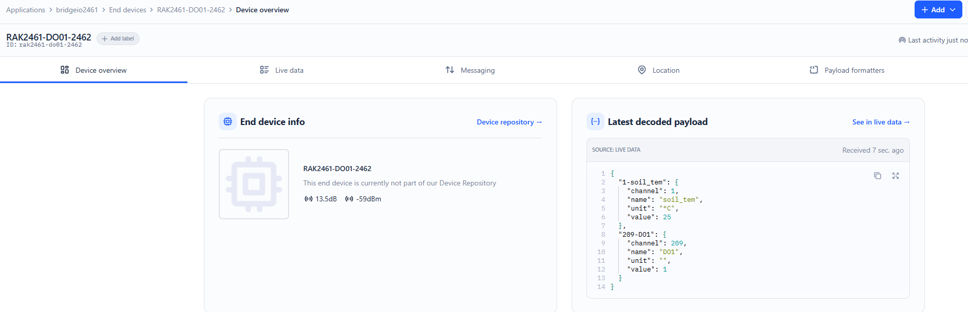 Figure 1: Integration tab5
:::
If the payload formatters are not configured, The Things Stack will be unable to properly decode uplink data or encode downlink commands. This will result in either raw/unreadable payloads being displayed or downlink control commands failing to reach the device in the correct format.
Onboard to The Things Stack Server
This feature provides a one-click onboarding capability. It automatically registers the current Bridge IO device to a specified application on your The Things Stack server, populating essential device parameters like DevEUI and AppKey. This eliminates manual device creation and reduces configuration errors.
Configuration Steps
-
In the Integration module, navigate to the The Things Stack menu and click Onboard to The Things Stack Server.
-
Select an existing TTN server and click the target Application.
NOTEIf no server is available, click Create New to add one. For detailed steps, refer to Create TheThingsStack Server.
-
On the Add New The Things Stack Server page, click OK. The device will then appear automatically under the TTN application.
Profiles
The Profiles feature allows you to save the complete configuration of a Bridge IO device (including LoRaWAN parameters, RS485 polling tasks, AI/AO calibration values, and more) as a named template. This is useful for:
-
Configuration Rollback: Quickly revert a device to a known working state if configurations are mistakenly changed.
-
Rapid Network Joining: Enable immediate network access for devices not yet registered on a LoRaWAN Network Server (LNS).
-
Bulk Deployment: Efficiently deploy a verified configuration to multiple devices of the same model, ensuring consistency and saving configuration time.
-
When performing bulk deployment, the Bridge IO device models must be identical, and their interface types and connected sensor types must also match.
-
If a device has already been registered with a LoRaWAN server, applying a Profile is generally not required. However, if a device is not yet registered, you must apply the corresponding Profile to enable it to join the network.
System Settings
This tab shows the general information about your device, you can choose the power output and you can perform system resets and updates.
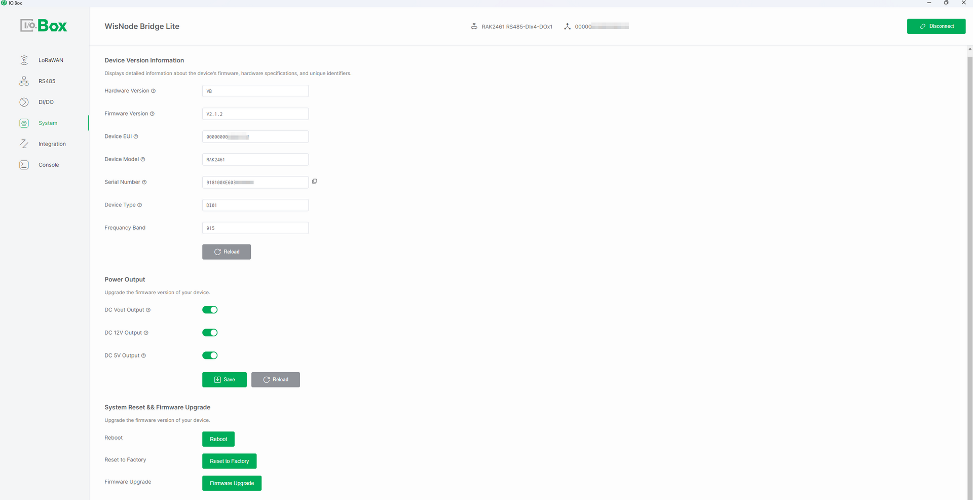 Figure 1: System tab
Device Version Information
- Hardware Version - Displays the specific version of the device's hardware.
- Firmware Version - Displays the device's firmware version.
- Device EUI - Displays the unique identifier assigned by the manufacturer.
- Device Model - Displays the specific model name or number of the device.
- Serial Number - Displays the device's serial number of the device.
- Device Type - Indicates the device's category, defining its interface types and functionalities. For detailed specifications, refer to the model information.
- Frequency Band - The device's frequency band.
Power Output
-
DC Vout Output:Toggle to enable or disable the Vout power output. When enabled, Vout passes through the same voltage as the Vin input.
-
DC 5V Output:Toggle to enable or disable the 5 V power output for connected peripherals or devices that require a 5 V supply.
-
DC 12V Output :Toggle to enable or disable the 12V_Out power output, which provides a 12 V/0.5 A power output when enabled.
- The Power Output option is not available in RAK2470.
- If the device does not have its own power supply, you must enable the appropriate power output here to provide power to the device.
System Reset && Firmware Upgrade
-
Reboot: Click Reboot to restart the device. This is typically used to apply configuration changes or recover from temporary system issues.
-
Reset to Factory: Click Reset to Factory to restore the device to its factory default settings. This action will erase all user configurations and cannot be undone.
-
Firmware Upgrade: Click Firmware Upgrade to upload and install a new firmware version on the device. This is used to apply feature updates, bug fixes, or performance improvements.
Console
This tab shows a log of the AT commands sent by the IO.Box and the device's responses.
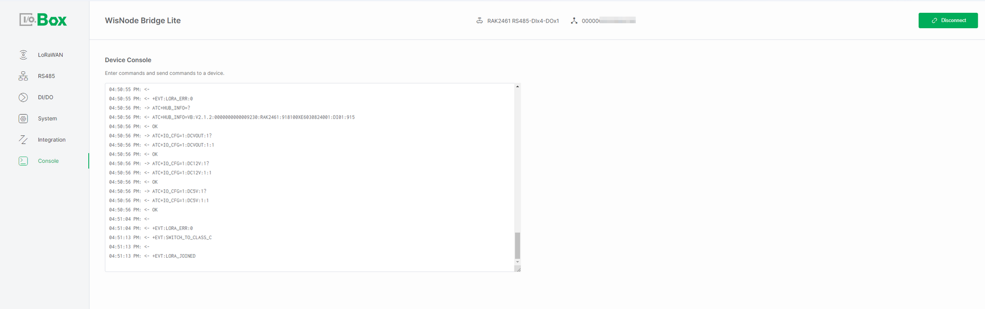 Figure 1: Console tab