RAK10702 WisBlock Indoor Comfort Node Assembly Guide
This guide shows you step by step how to assemble the electronic components and how to assemble them in the (optional) enclosure. This guide is for the version with the 4.2" E-Ink display. If you are using the version without the display, you can skip certain steps.
Assembly Guide
As the RAK10702 is a DIY product, this document will guide how to correctly assemble the electronic components and place them in the optional available 3D-printed enclosure.
Assemble the Front Sensor Component RAK13013
- Plug the Wisblock RAK1901, RAK12010 and RAK12047 on the RAK13013 sensor carrier module. Fix the modules with 3 pcs M1.2*3 Screws.
- Insert the 15-pin FPC into the connector on the back side of the PCB. Make sure to secure the FPC in the connector with the lever on the connector.
Prepare and Assemble the Particulate Matter Sensor
- Stick the double-side adhesive EVA on the holder PCB. The position refers to the image.
- Assemble the sensor on the holder PCB, plug the connector of the sensor into the socket on the holder PCB, and check that the sensor sticks on the double-side adhesive EVA.
- Insert 6-pin FPC into the connector on the holder PCB. Make sure to secure the FPC in the connector with the lever on the connector.
Prepare the Display
This step is only required if the kit includes the E-Ink display.
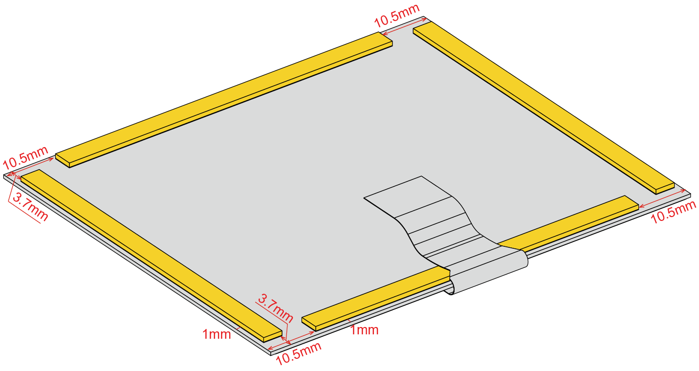
Stick the adhesive EVA on the back of the display screen. The distance to the edge is 1 mm.
Refer to the image for the positioning.
Prepare the Enclosure Lid
Tear off the release paper of the glass, and stick the glass on the top cover.
The glass is not included in the PCB kits. It should be ordered separately.
Assemble the WisBlock modules
- Plug the Wisblock RAK14000 module to the connector on the back of the Base Board. Fix the module with 3 pcs. of M1.2*3 screws.
- Plug the Wisblock Modules RAK12037, RAK12067, and RAK12002 into the top slots of Base Board. Fix the modules with 7 pcs. of M1.2*3 screws.
The following steps are only required if the kit includes the enclosure.
Assemble the Front Sensor Carrier and the Base Board on the Enclosure Lid
- Fix the front sensor carrier PCB on the mounting plate with 3 pcs. of ST2.0*3 Self tapping screws. The FPC passes through the slot on the mounting plate.
- Fix the Base board and sensor on the mounting plate with 9 pcs. of ST2.2*4.5 self-tapping screws.
- Insert the two FPCs from the PM sensor and the front sensor carrier in the sockets on the Base board. The operation of the connector is the same as Figure 12.
- Bend the FPC of the display screen carefully, and insert it into the connector of the RAK14000. Then close the display screen into the slot of the mounting plate.
- Place the top cover on the mounting plate. Flip both the mounting plate and the top cover over and fix them with 6 pcs of ST2.2*5 countersunk head self-tapping screws.
- You can fix the enclosure on the wall or other position with screws. Before fixing, the power cable should be passed through from the slot hole of the enclosure. Then connect the power cable with the terminal connector on the Base board.
- Place the slot holes on the top cover on the pegs on the enclosure, rotate the top cover, and clip it into the bottom part of the enclosure.
- You can fix a screw on the enclosure to avoid opening the device.
This step is not mandatory.
Opening the Enclosure
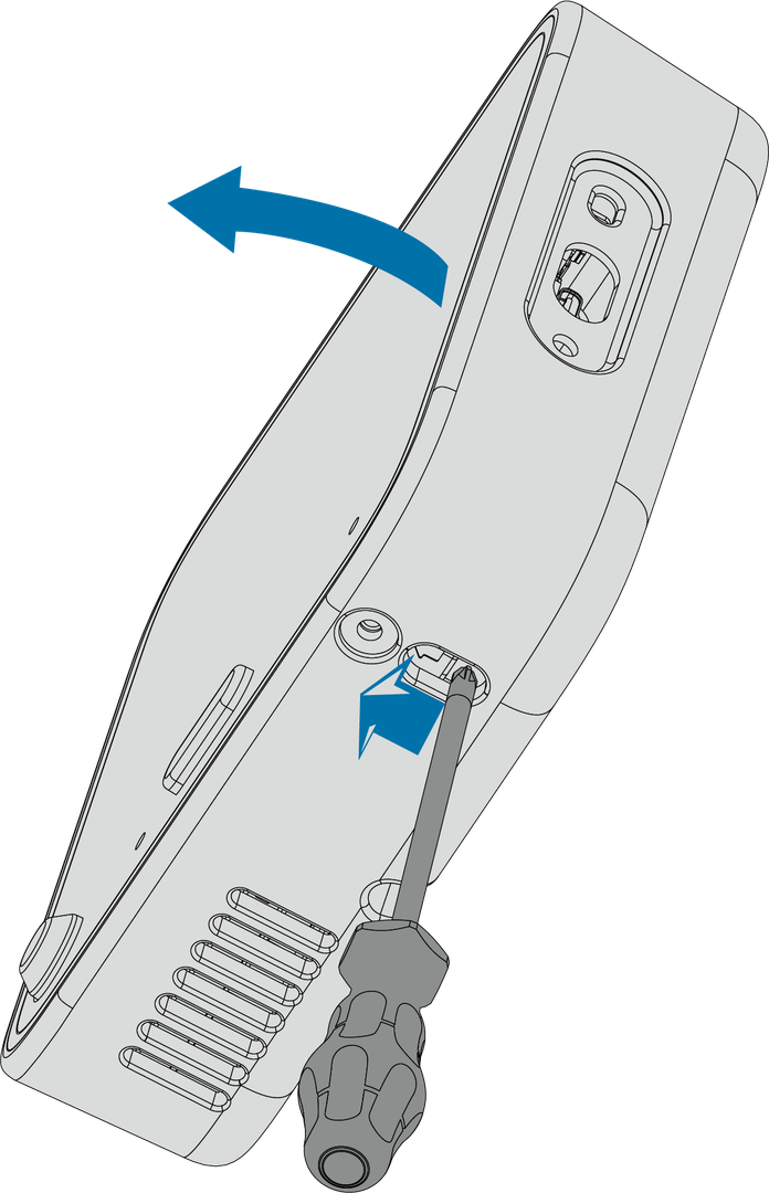
If you want to open the enclosure, insert a screwdriver in the hole in the below image, and lever open the top cover.


