RAK12005 WisBlock Rain Sensor Module Installation Guide
WisBlock Module Installation
WisBlock can integrate this module, which extends the WisBlock system with an electroconductive liquid detection capability. For more information about RAK12005, refer to the Datasheet.
The RAK12005 module provides information about:
- Rain/Water Detection - measures resistance changes caused by water or condensed fog.
The RAK12005 module can be connected to the sensor slot of the WisBlock Base to communicate with the WisBlock Core. Always secure the connection of the WisBlock module by using compatible screws.
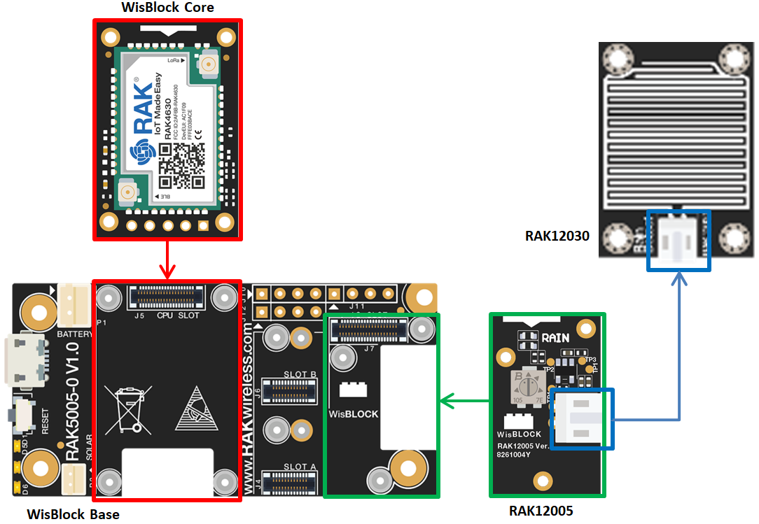 Figure 1: RAK12005 connection to WisBlock Base
Select a suitable WisBlock Base and WisBlock Core according to your application requirements and hardware configuration.
RAK12030 Sensing Pad
The sensor contains a sensing pad that you can place the sensor exposed under the open sky where it can be affected by rainfall and keep your WisBlock solution in a dry place or inside a waterproof enclosure.
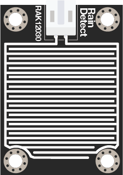 Figure 1: RAK12030 Module
RAK12005 Sensor Module
The RAK12005 module produces an output voltage depending on the resistance of the sensing pad. The signal from the sensing pad is fed to an MCP606 Comparator to digitize it then the comparator output is tied to the IO pin on the WisConnector. The module also has a built-in potentiometer for sensitivity adjustment of the digital output. Keep the RAK12005 in a dry place or inside a waterproof enclosure, just make sure not to wet this part of the module.
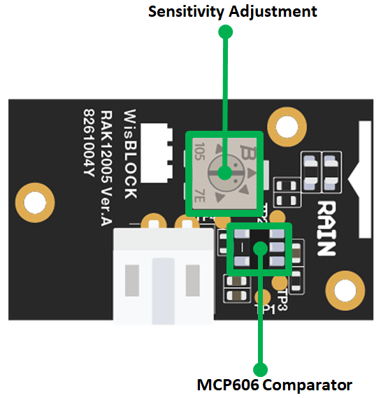 Figure 1: RAK12005 Module
Assembling and Disassembling of WisBlock Modules
Assembling
The RAK12005 module can be mounted on the IO slot of the WisBlock Base board.Always secure the connection of the WisBlock module by using compatible screws.
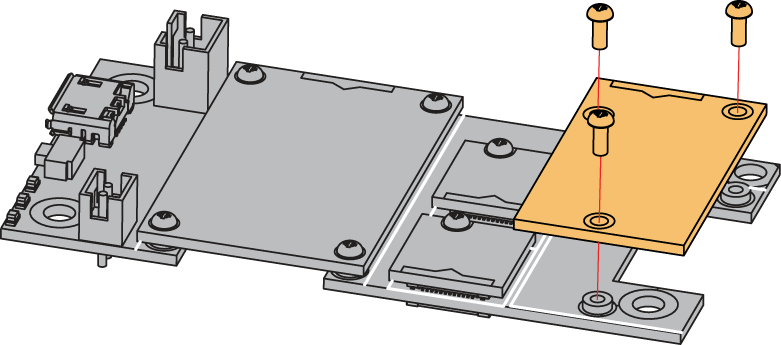 Figure 1: RAK12005 mounting connection to WisBlock Base module
Disassembling
The procedure in disassembling any type of WisBlock modules is the same.
- First, remove the screws.
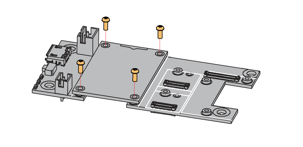 Figure 1: Removing screws from the WisBlock module
- Once the screws are removed, check the silkscreen of the module to find the correct location where force can be applied.
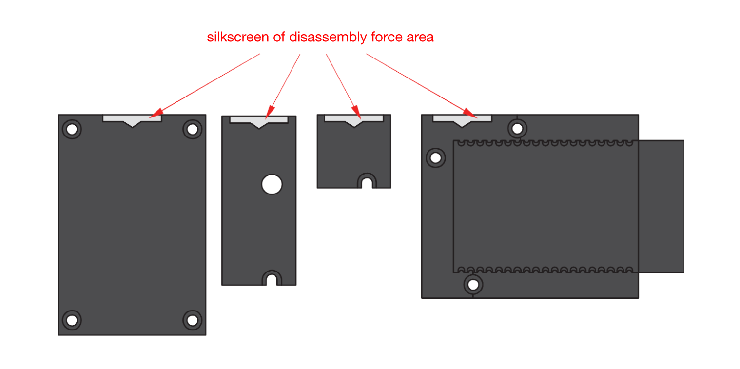 Figure 1: Finding the proper position to detach the WisBlock module
- Apply even force to the module at the position of the connector to detach the module from the WisBlock Base.
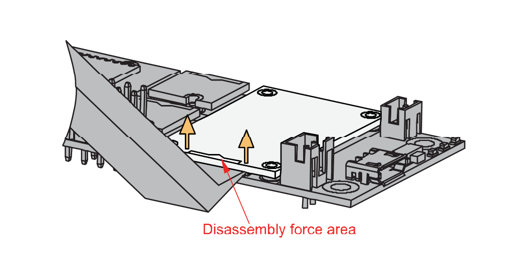 Figure 1: Applying even forces on the proper location of a WisBlock module
If you will connect other modules to the remaining WisBlock Base slots, check on the WisBlock Pin Mapper tool for possible conflicts.
After all this setup, you can now connect the battery (optional) and USB cable to start programming your WisBlock Core.
- Batteries can cause harm if not handled properly.
- Only 3.7-4.2 V Rechargeable LiPo batteries are supported. It is highly recommended not to use other types of batteries with the system unless you know what you are doing.
- If a non-rechargeable battery is used, it has to be unplugged first before connecting the USB cable to the USB port of the board to configure the device. Not doing so might damage the battery or cause a fire.
- Only 5 V solar panels are supported. Do not use 12 V solar panels. It will destroy the charging unit and eventually other electronic parts.
- Make sure the battery wires match the polarity on the WisBlock Base board. Not all batteries have the same wiring.


