RAK13005 WisBlock LIN Module Datasheet
Overview
Description
The RAK13005 is a Local Interconnect Network (LIN) transceiver module, used in automatic technologies that can be mounted on the IO slot of the WisBlock Base board. It is designed for in-vehicle networks using data transmission rates from 2.4 kBaud to 20 kBaud, and it uses the TLE7259-3 chip from Infineon.
This module offers safe communication over up to 40 m distance between the LIN bus nodes. Besides the use in an automotive environment, it can be implemented in home appliances and industrial automation. The LIN bus technology consists of Peripheral (Slave) and Controller (Master) Nodes which are both supported by RAK13005.
Features
-
Module specifications
- Single-wire LIN transceiver for transmission rates up to 20 kBaud
- Supports both Controller(Master) and Peripheral(Slave) modes
- Compliant to ISO 17987-4 and LIN Specification 2.2A
- Very low current consumption in sleep mode with wake-up functions
- Support 12 V and 24 V LIN bus power supply
- Digital I/O levels compatible with 3.3 V and 5 V microcontrollers
- Chipset: Infineon TLE7259-3
-
Size
- 25 x 35 mm
Specifications
Overview
Mounting
The RAK13005 module can be mounted on the IO Slot of a WisBlock Base board. Figure 1 shows the mounting mechanism of the RAK13005 on a WisBlock Base board, such as the RAK5005-O.
 Figure 1: RAK13005 WisBlock LIN Module mounting
Hardware
The hardware specification is categorized into five parts. It shows the chipset of the module and the pinouts and its corresponding functions and diagrams. It also presents the parameters and their standard values in terms of electrical and mechanical.
Chipset
| Vendor | Part number |
|---|---|
| Infineon | TLE7259-3 |
Pin Definition
The RAK13005 WisBlock LIN module module comprises a standard 40-pin WisConnector. The WisConnector allows the RAK13005 module to be mounted on a WisBlock Base board, such as RAK5005-O. The pin order of the connector and the pinout definition is shown in Figure 2.
- The UART related pins, 3V3, and GND are connected to this module.
- The IO6 pin is connected to LIN Enable input pin (EN).
- The IO5 pin is connected to MCU_WK pin.
 Figure 1: RAK13005 WisBlock LIN Module Pinout Diagram
Electrical Characteristics
Recommended Operating Conditions
| Symbol | Description | Min. | Nom. | Max. | Unit |
|---|---|---|---|---|---|
| VS | Supply Voltage Range for Normal Operation | 5.5 | - | 27 | V |
| Tj | Junction Temperature | -40 | - | 85 | ℃ |
| Isleep | Current Consumption at VS in Sleep Mode | - | 5 | 12 | uA |
Mechanical Characteristic
Board Dimensions
Figure 3 shows the dimensions and the mechanic drawing of the RAK13005 module.
 Figure 1: RAK13005 WisBlock LIN Module Mechanic Drawing
WisConnector PCB Layout
 Figure 1: WisConnector PCB Footprint and Recommendations
Schematic Diagram
Figure 5 shows the RAK13005 schematic.
- J2 is the LIN bus connector.
- J1 is the 40-pin WisConnector.
- VS is the LIN bus power supply pin.
- EN is the Enable input IO6 which is an active-high pin.
- WK is the Wake input which is an active-low pin.
- VIN range is 5.5 to 27 V.
The MCU_WK pin (IO5) is connected to the Q1 transistor, and the Q1 collector is connected to the WK pin. Q1 works as an inverter, thus in normal operation, set MCU_WK to the high level.
 Figure 1: RAK13005 Schematic Diagram
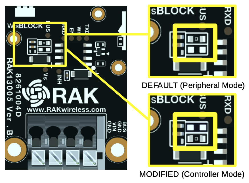
- With R5 soldered, the RAK13005 works as a LIN controller(master).
- With R4 soldered, the RAK13005 works as a LIN peripheral(slave).
 Figure 1: RAK13005 LIN Mode Configuration