RAK13005 WisBlock LIN Module Quick Start Guide
Prerequisite
What Do You Need?
Before going through each and every step on using the RAK13005 WisBlock module, make sure to prepare the necessary items listed below:
Hardware
- RAK13005 WisBlock LIN Module - Controller/Master Mode
- RAK13005 WisBlock LIN Module - Peripheral/Slave Mode
- Your choice of WisBlock Base
- Your choice of WisBlock Core
- USB Cable
- Li-Ion/LiPo battery (optional)
- Solar charger (optional)
- External power source ( 5.5 V to 27 V )
Software
Arduino
- Download and install Arduino IDE.
- To add the RAKwireless Core boards on your Arduino Boards Manager, install the RAKwireless Arduino BSP.
Product Configuration
Block Diagram
Hardware Setup
RAK13005 is a WisBlock LIN Module that extends the WisBlock system to be used on communication protocol called Local Interconnect Network (LIN). This communication is initiated by the automotive industry for the communication of in-vehicle devices on cars. Today, LIN is also used in other applications that require a robust communication line. For more information about the RAK13005, refer to the Datasheet.
Pin Definition
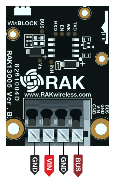 Figure 1: RAK13005 Pin Definition
LIN Peripheral and Controller Mode Hardware Configuration
RAK13005 supports both Controller(master) and Peripheral(slave) modes. The two modes uses the same RAK13005 circuit design and configuration is simply determined by an SMD resistor. The resistor location is shown in Figure 2.
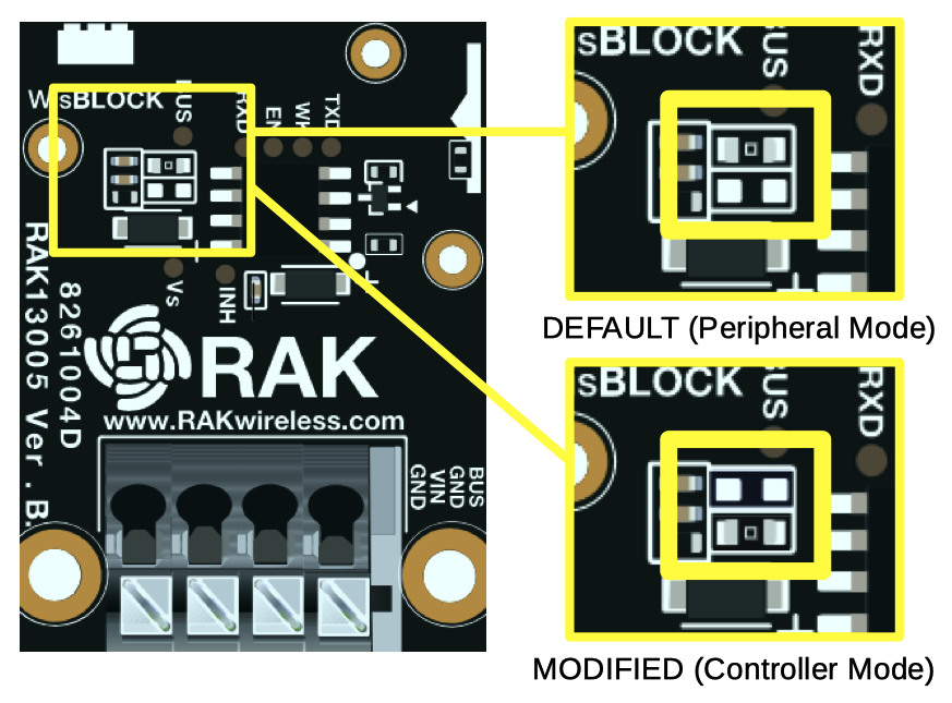 Figure 1: RAK13005 LIN Mode Configuration
Assembling and Disassembling of WisBlock Modules
Assembling
The RAK13005 module can be mounted on the IO slot of the WisBlock Base board, as shown in Figure 3. Also, always secure the connection of the WisBlock module by using the compatible screws.
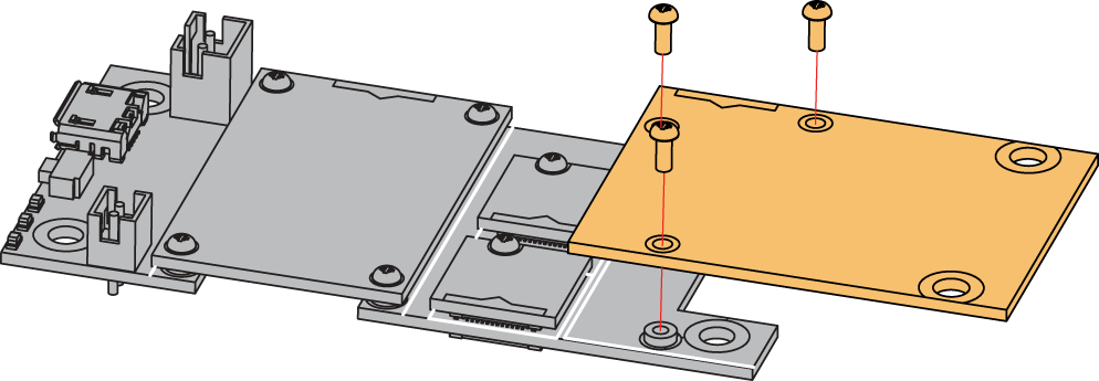 Figure 1: RAK13005 mounting connection to WisBlock Base module
RAK13005 Connector Crimping Mechanism
The RAK13005 features a fast-crimping terminal connector to simplify and ensure the wiring process on the fields. The fast-crimping terminal can support cable with a width between 20 AWG to 24 AWG. The usual stripping length is around 6 to 7 mm.
As shown in Figure 4, during the crimping process, you should first press down and maintain the spring head of the crimping terminal firmly, then insert the stripped cable head into the corresponding connector’s hole. Once inserted correctly, release the spring head, and the crimping process is completed.
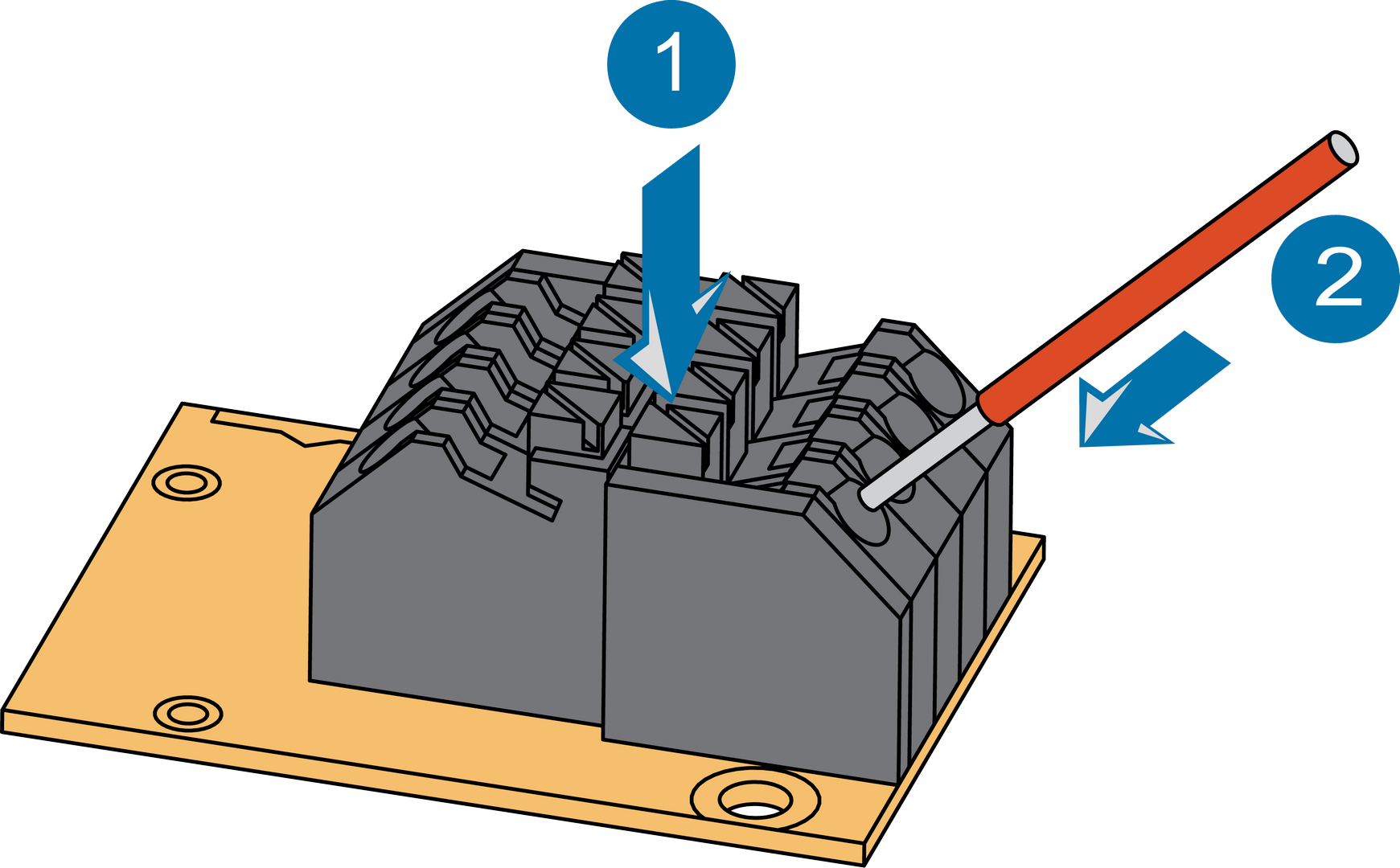 Figure 1: RAK13005 Module Connector
Disassembling
The procedure in disassembling any type of WisBlock modules is the same.
- First, remove the screws.
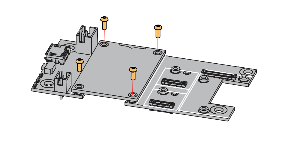 Figure 1: Removing screws from the WisBlock module
- Once the screws are removed, check the silkscreen of the module to find the correct location where force can be applied.
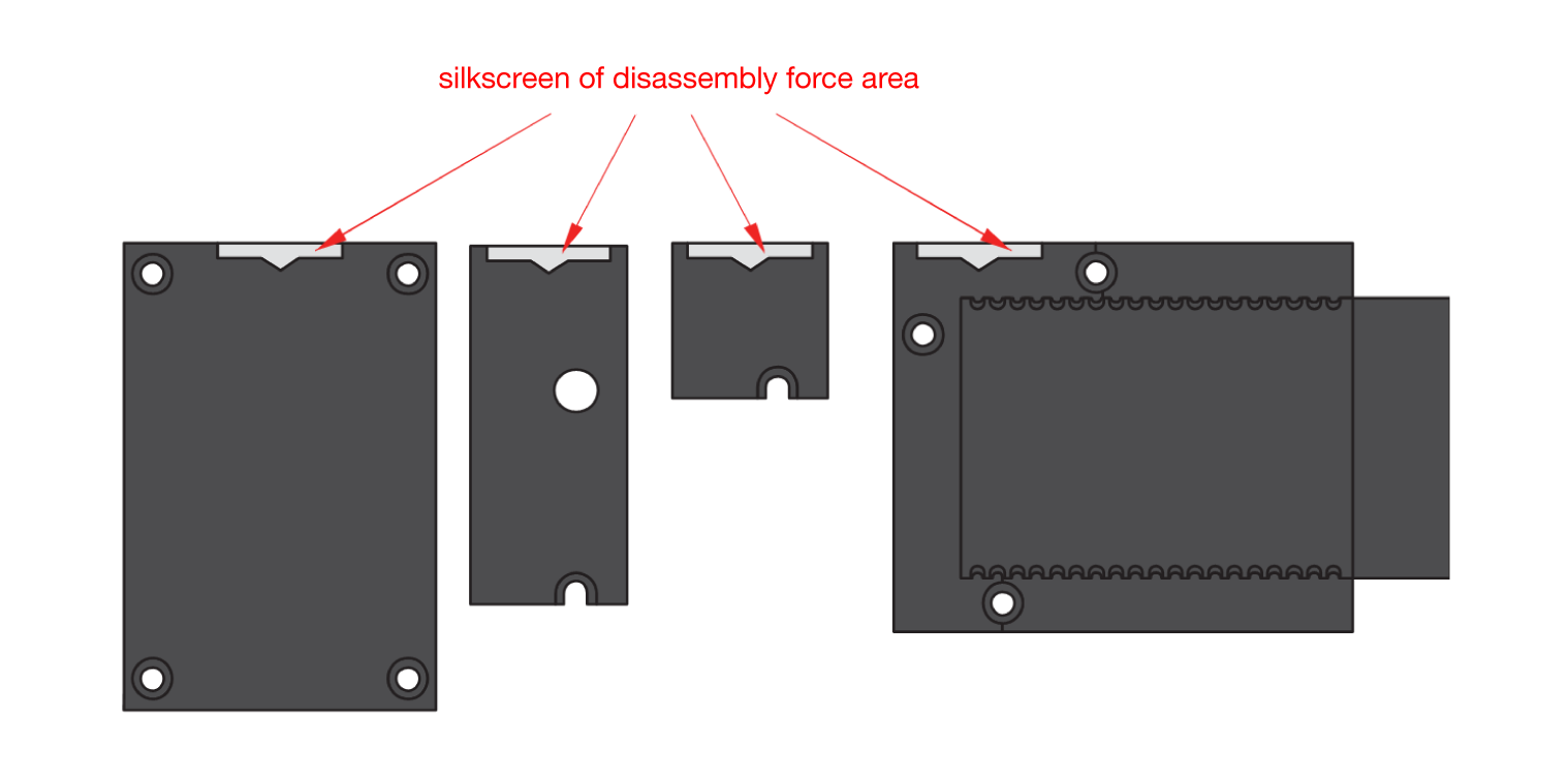 Figure 1: Detaching silkscreen on the WisBlock module
- Apply force to the module at the position of the connector, as shown in Figure 7, to detach the module from the baseboard.
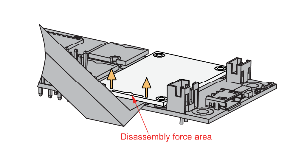 Figure 1: Applying even forces on the proper location of a WisBlock module
If you will connect other modules to the remaining WisBlock Base slots, check on the WisBlock Pin Mapper tool for possible conflicts.
Now, you can connect the battery (optional) and USB cable to start programming your WisBlock Core.
- Battery can cause harm if not handled properly.
- Only 3.7-4.2 V Rechargeable LiPo batteries are supported. It is highly recommended not to use other types of batteries with the system unless you know what you are doing.
- If a non-rechargeable battery is used, it has to be unplugged first before connecting the USB cable to the USB port of the board to configure the device. Not doing so might damage the battery or cause a fire.
- Make sure the battery wires match the polarity on the RAK WisBlock Base Board. Not all batteries have the same wiring.
- Only 5 V solar panels are supported. Do not use 12 V solar panels. It will destroy the charging unit and eventually other electronic parts.
Software Configuration and Example
In this example, you will be using two RAK13005 Modules to demonstrate LIN functionality.
These are the quick links that go directly to the software guide for the specific WisBlock Core module you use:
- RAK13005 in RAK4631 WisBlock Core Guide
- RAK13005 in RAK11200 WisBlock Core Guide
- RAK13005 in RAK11310 WisBlock Core Guide
RAK13005 in RAK4631 WisBlock Core Guide
Arduino Setup
Figure 8 is an illustration on how to use two RAK13005 LIN modules for communication applications. One RAK13005 is configured as Controller and the other RAK13005 is configured as Peripheral. The SMD resistors that set the mode are highlighted in a yellow box.
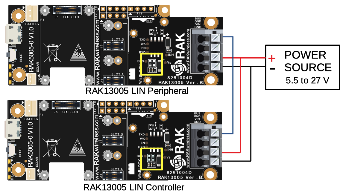 Figure 1: Two RAK13005 Interconnection for Controller and Peripheral mode
- Select the RAK4631 WisBlock Core.
- Install the RAKwireless Arduino BSP to find the RAK4631 in the Arduino Boards Manager.
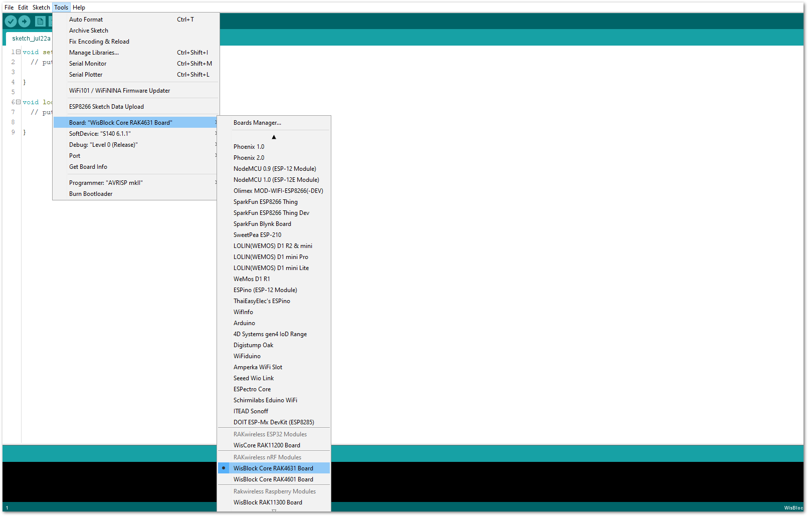 Figure 1: Selecting RAK4631 as WisBlock Core
- Next, install the RAKwireless TLE7259 library using the Arduino Library manager.
- Select
Sketchfollowed byInclude LibrarythenManage Libraries.
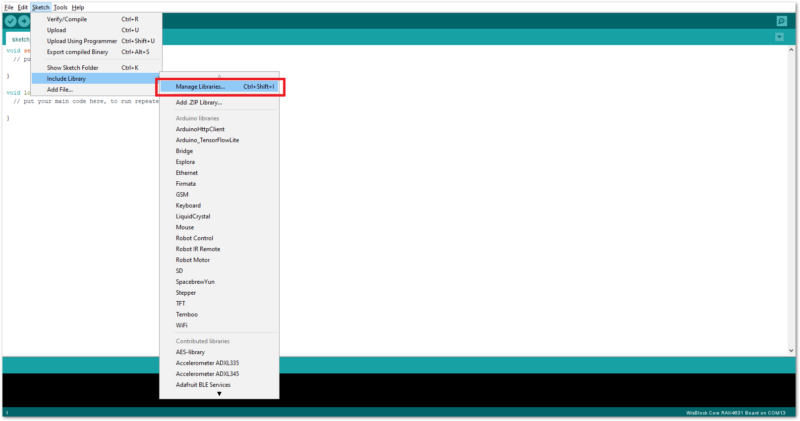 Figure 1: Open Arduino Library Manager
- Search for RAKwireless TLE7259 on the Library Manager text box.
- Select the latest version of the library then click Install button.
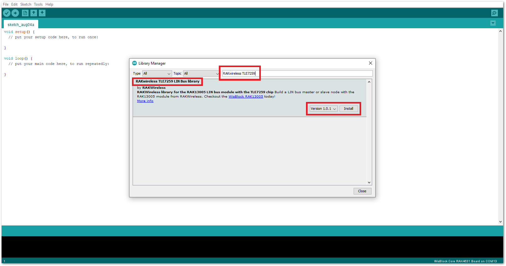 Figure 1: Look for RAKwireless TLE7259 LIN Bus Library
- After successful installation, close the Arduino Library window.
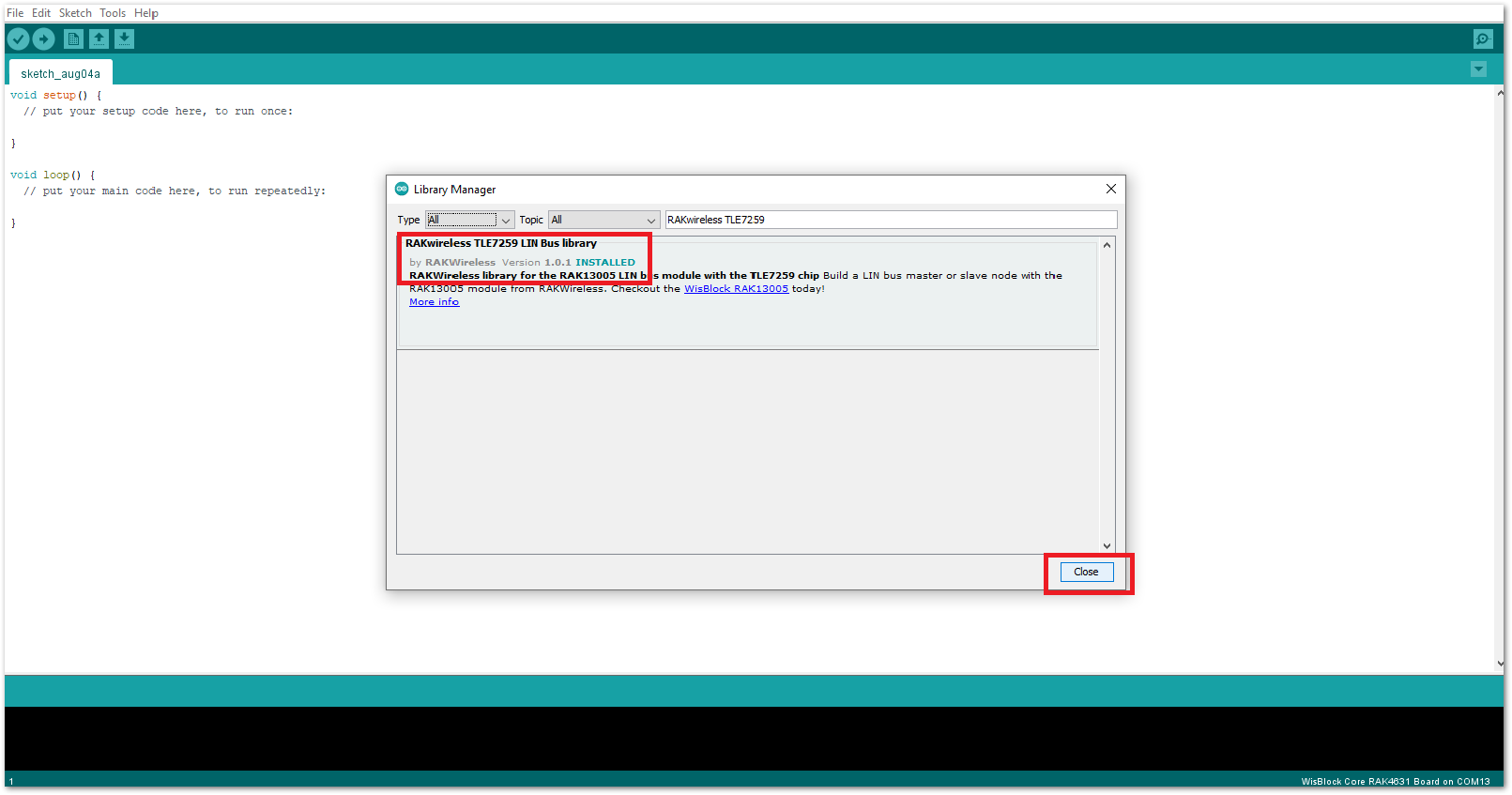 Figure 1: RAKwireless TLE7259 LIN Bus Library Successfully Installed
- Upload the
RAK13005_linbus_masterController sketch.
- Connect the first WisBlock with the RAK13005 module in Controller mode and select the
RAK13005_linbus_master.
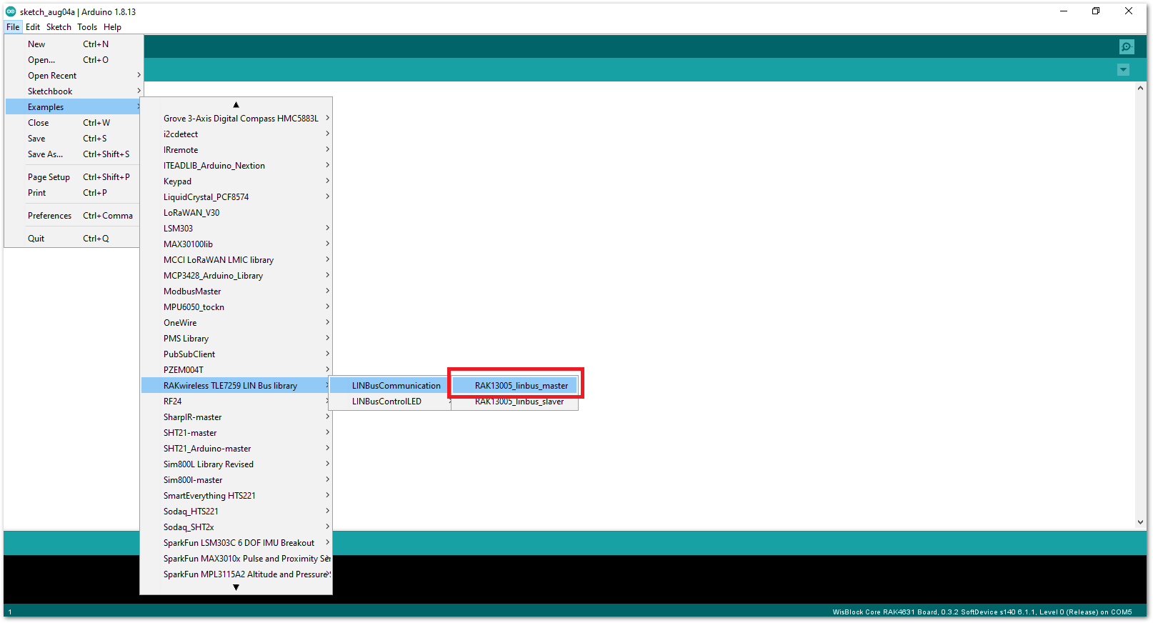 Figure 1: Open the code for the RAK13005 Controller
- Select the port where RAK4631 WisBlock Core is connected.
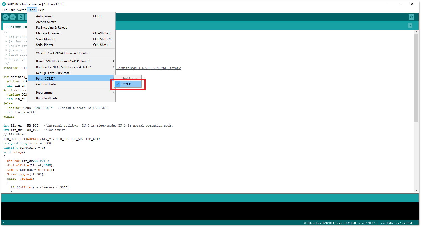 Figure 1: Select the Serial Port of RAK4631 for the RAK13005 LIN module in controller mode.
- Now, upload the
RAK13005_linbus_mastercode to the WisBlock Core.
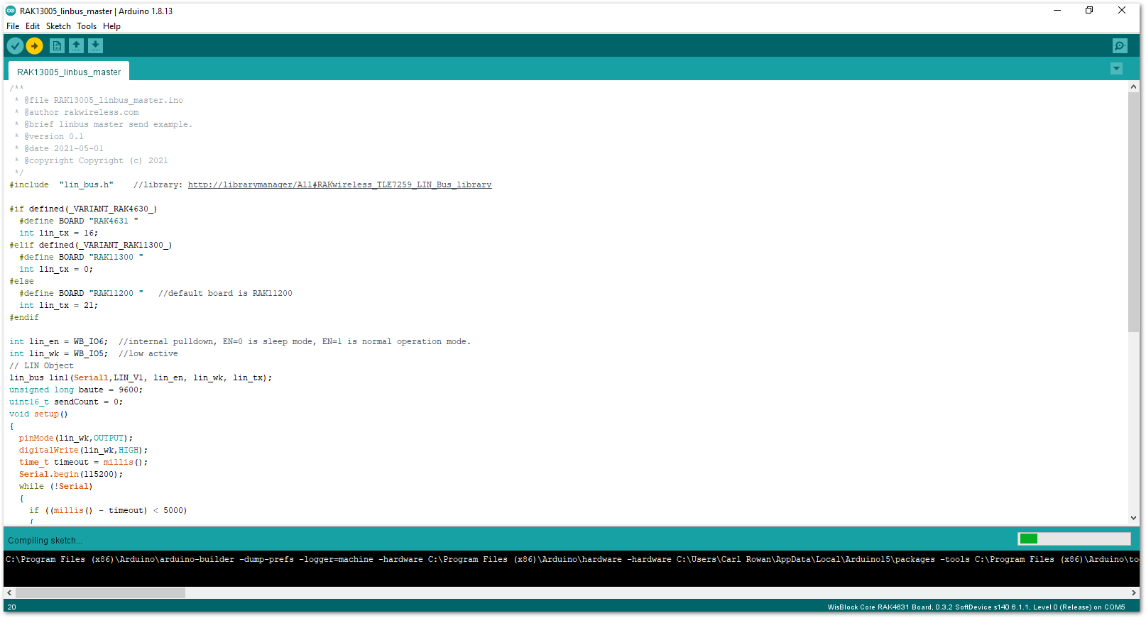 Figure 1: Uploading RAK13005_linbus_master code
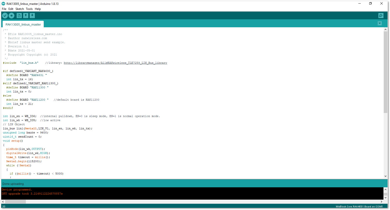 Figure 1: Successful code Upload
- After the successful code upload, you can now open the Serial Monitor and see the Serial output.
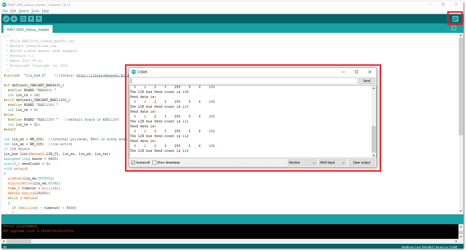 Figure 1: Serial Output of the RAK13005 Controller Mode
- Upload the
RAK13005_linbus_slaverPeripheral sketch.
- Connect the second WisBlock with the RAK13005 in Peripheral mode, then select
RAK13005_linbus_slaver.
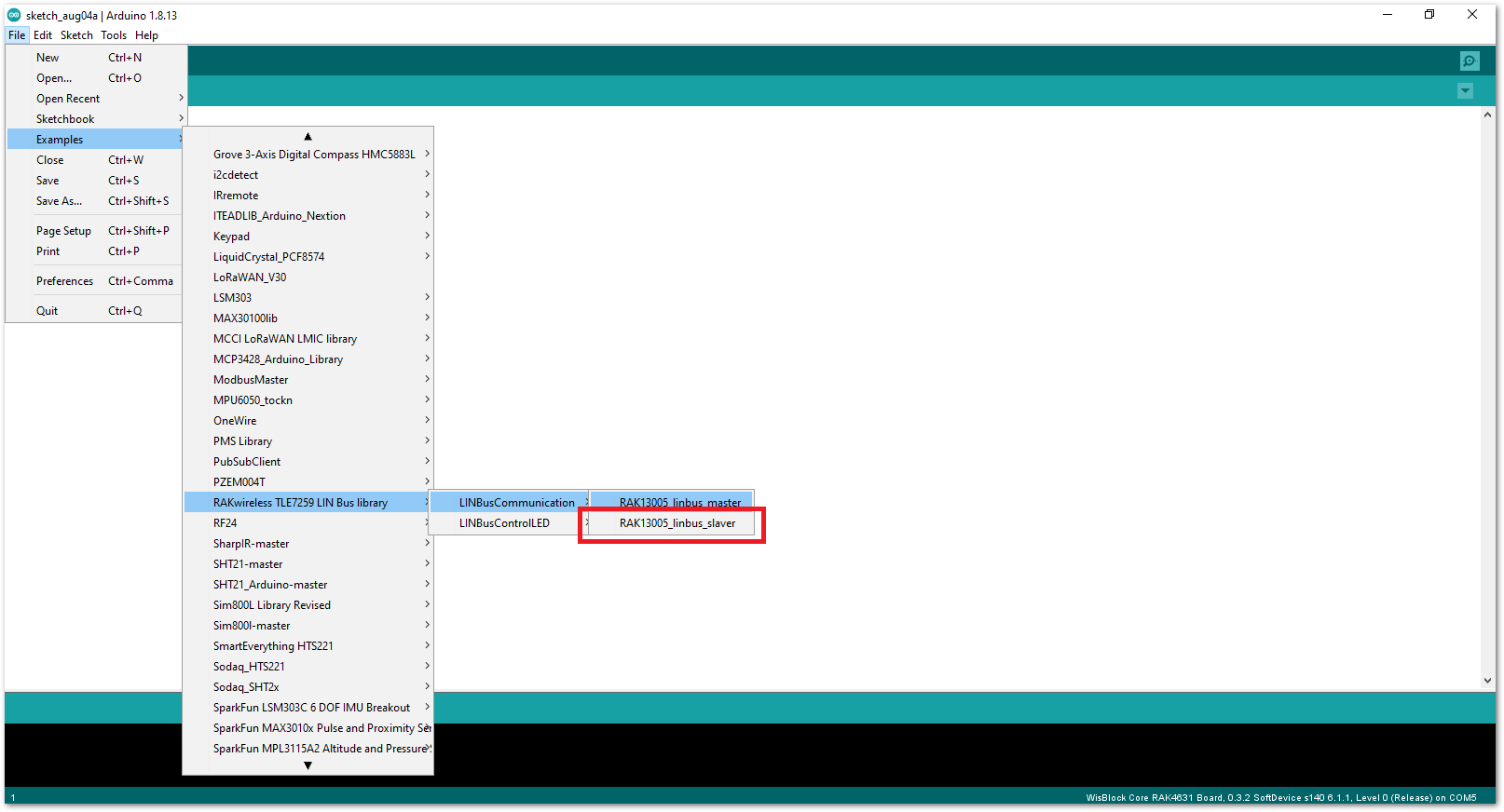 Figure 1: Open the code for the RAK13005 Peripheral
- Select the port, which is the additional port from the previous port for the controller. You should see two ports in your Arduino IDE.
 Figure 1: Select the Serial Port of RAK4631 for the RAK13005 LIN module in peripheral mode.
- After ensuring the port matching the RAK13005 LIN Peripheral, you can now upload the
RAK13005_linbus_slavercode.
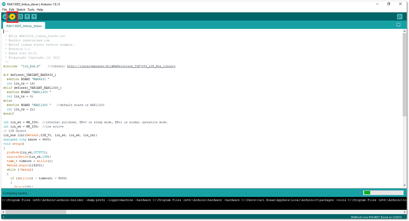 Figure 1: Uploading the RAK13005_linbus_slaver code
If you experience any error in compiling an example sketch, check the updated code for the RAK13005 WisBlock Core Module that can be found on the RAK13005 WisBlock Example Code Repository.
- Check Serial Monitor output.
- Check the Serial Monitor on the RAK13005 Peripheral device receiving the data coming from the RAK13005 Controller device. You must have the external power supply connected to have successful transmissions.
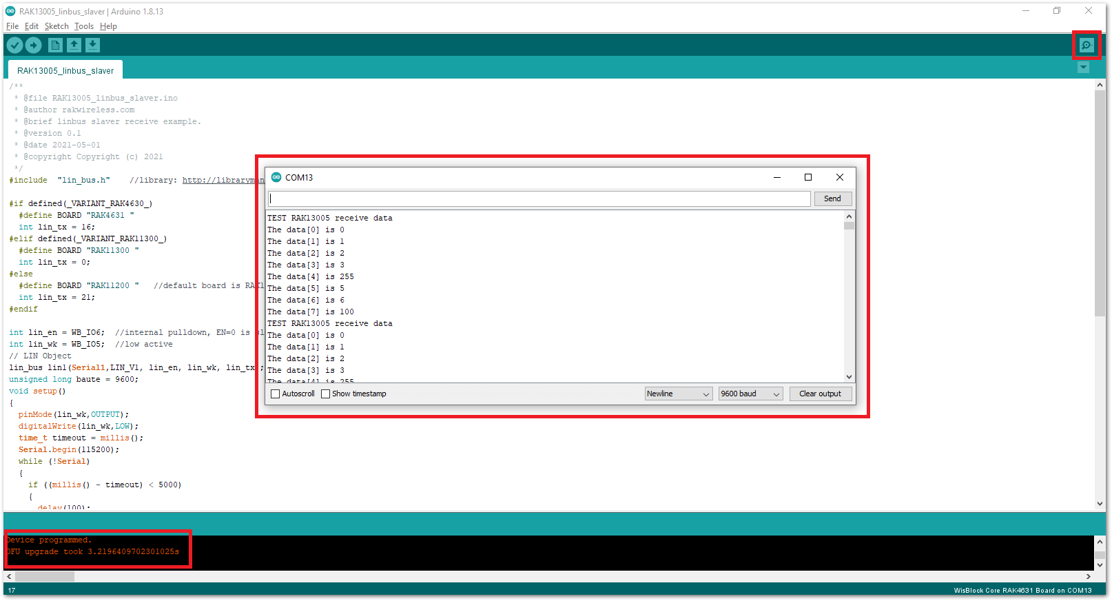 Figure 1: Serial Output of the RAK13005 Peripheral Mode
RAK13005 in RAK11200 WisBlock Core Guide
Arduino Setup
Figure 22 is an illustration on how to use two RAK13005 LIN modules for communication application. One RAK13005 is configured as Controller and the other RAK13005 is configured as Peripheral. The SMD resistors that set the mode are highlighted in a yellow box.
Figure 1: Two RAK13005 Interconnection for Controller and Peripheral mode- Select the RAK11200 WisBlock Core.
- Install RAKwireless Arduino BSP to find the RAK11300 in the Arduino Boards Manager.
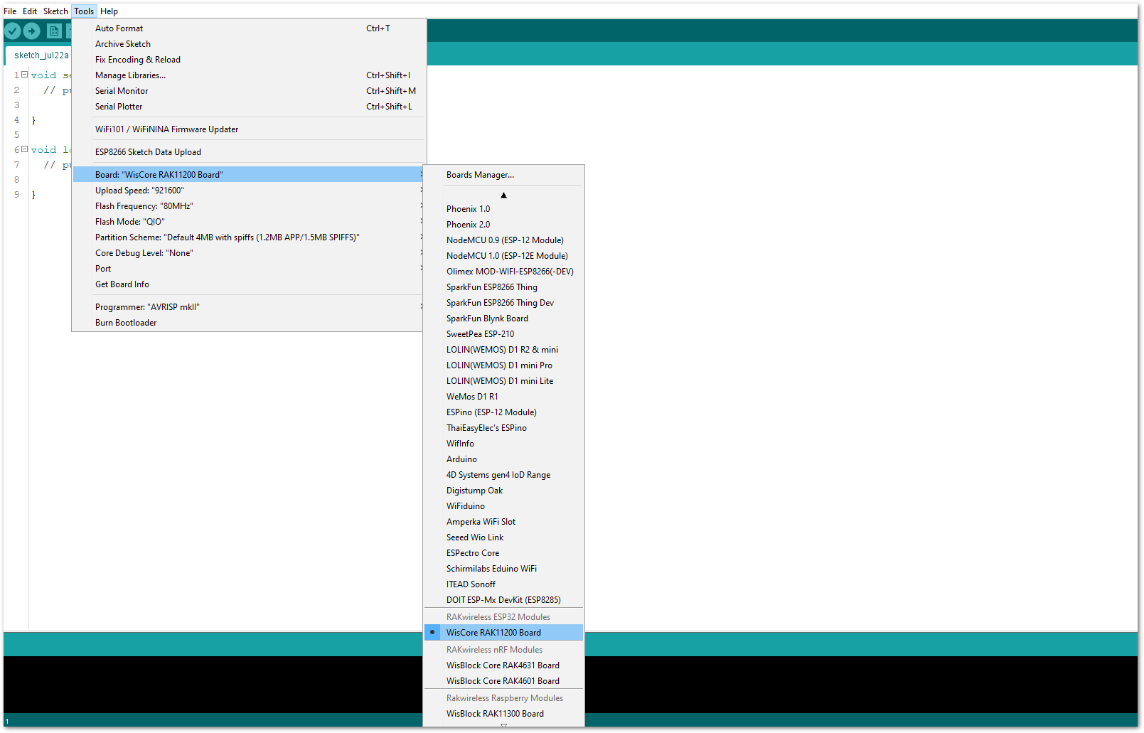 Figure 1: Selecting RAK11200 as WisBlock Core
- Next, install the RAKwireless TLE7259 library using the Arduino Library manager.
- Select
Sketchfollowed byInclude LibrarythenManage Libraries.
Figure 1: Open Arduino Library Manager-
Search for RAKwireless TLE7259 on Library Manager text box.
-
Select the latest version then click Install button.
Figure 1: Look for RAKwireless TLE7259 LIN Bus Library- After successful installation, close the Arduino Library window.
Figure 1: RAKwireless TLE7259 LIN Bus Library Successfully Installed- Upload the
RAK13005_linbus_masterController sketch.
-
Open the
RAK13005_linbus_masterController sketch. -
Connect the first WisBlock with the RAK13005 module in Controller mode and select the
RAK13005_linbus_master.
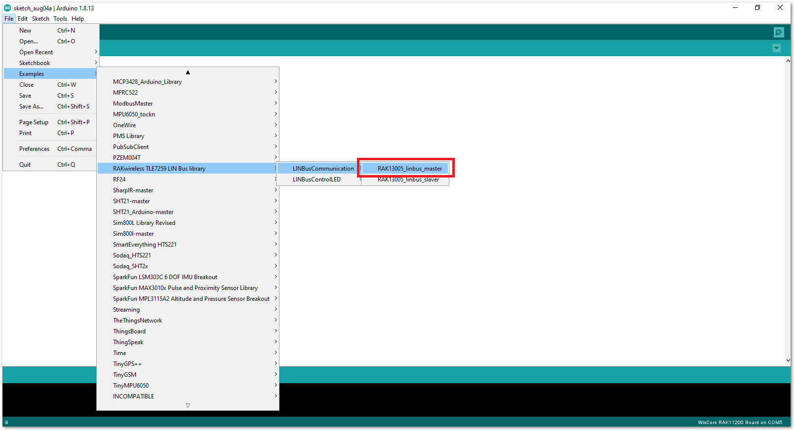 Figure 1: Open the code for the RAK13005 Controller
- Select the port where RAK11200 WisBlock Core is connected.
 Figure 1: Select the Serial Port of RAK11200 for the RAK13005 LIN module in controller mode.
- Now, upload the
RAK13005_linbus_mastercode to the WisBlock Core.
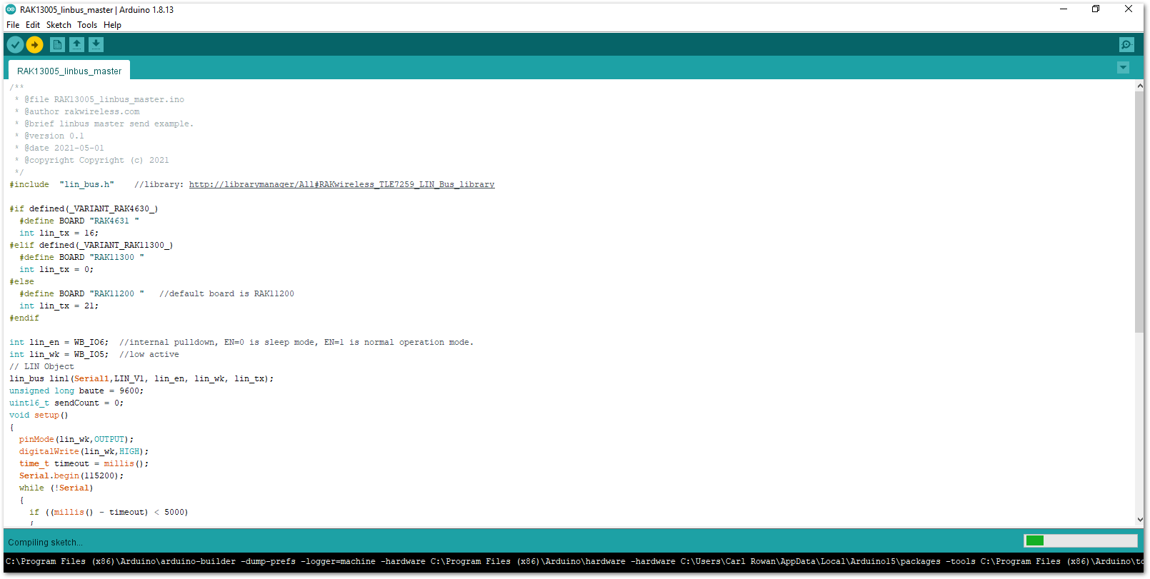 Figure 1: Uploading RAK13005_linbus_master code
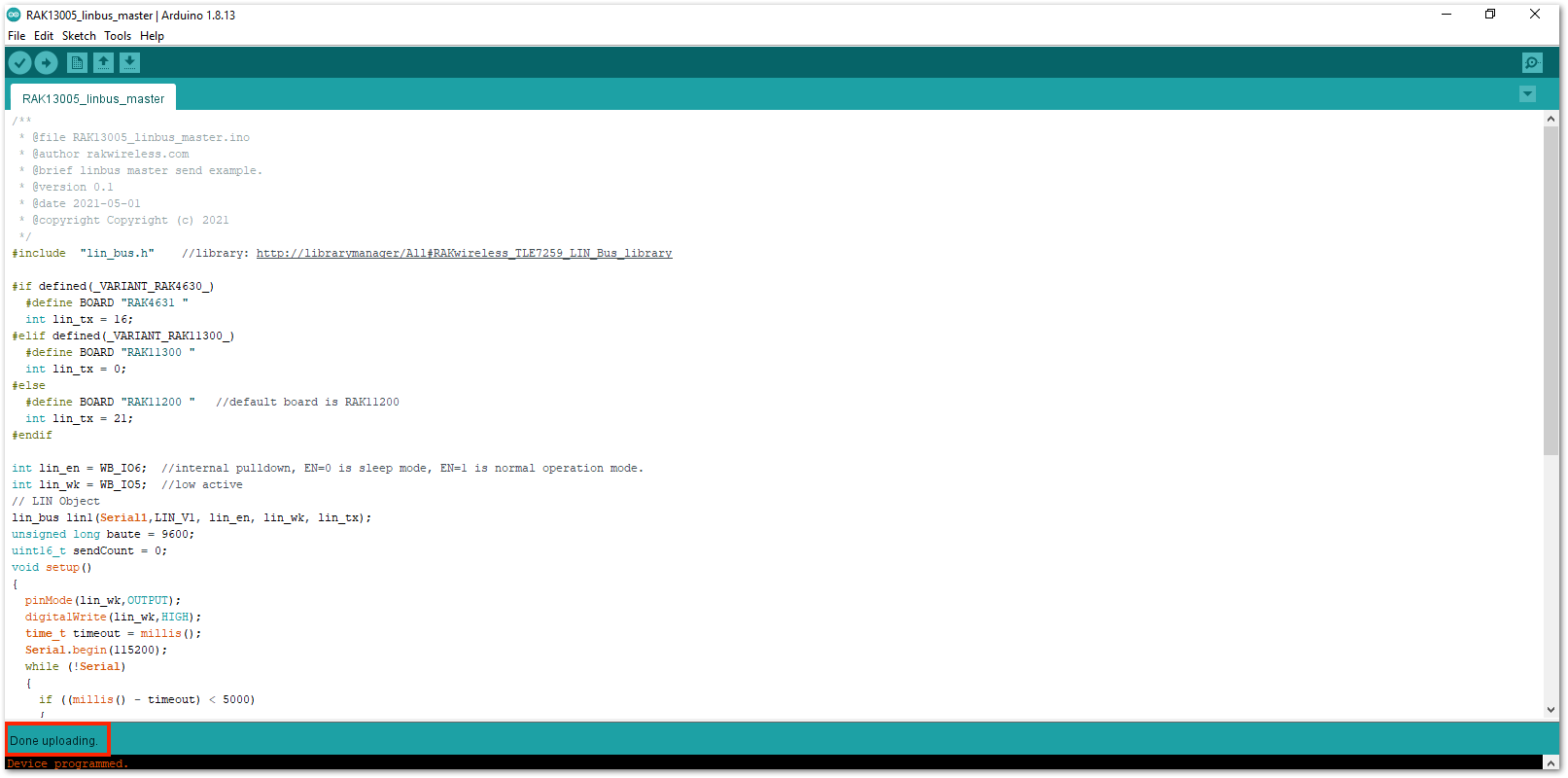 Figure 1: Successful code Upload
- After the successful code upload, you can now open the Serial Monitor and check the Serial output.
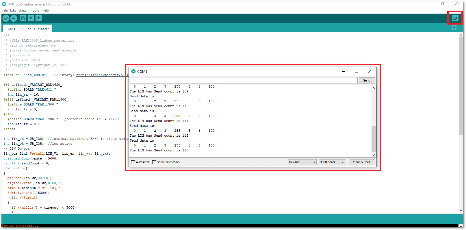 Figure 1: Serial Output of the RAK13005 Controller Mode
- Upload the
RAK13005_linbus_slaverPeripheral sketch.
- Connect the second WisBlock with the RAK13005 in Peripheral mode then select
RAK13005_linbus_slaver.
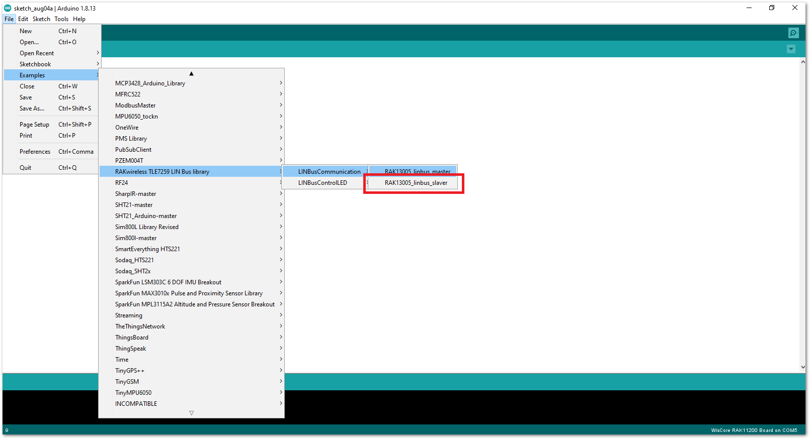 Figure 1: Open the code for the RAK13005 Peripheral
- Select the port, which is the additional port from the previous port for the controller. You should see two ports in your Arduino IDE.
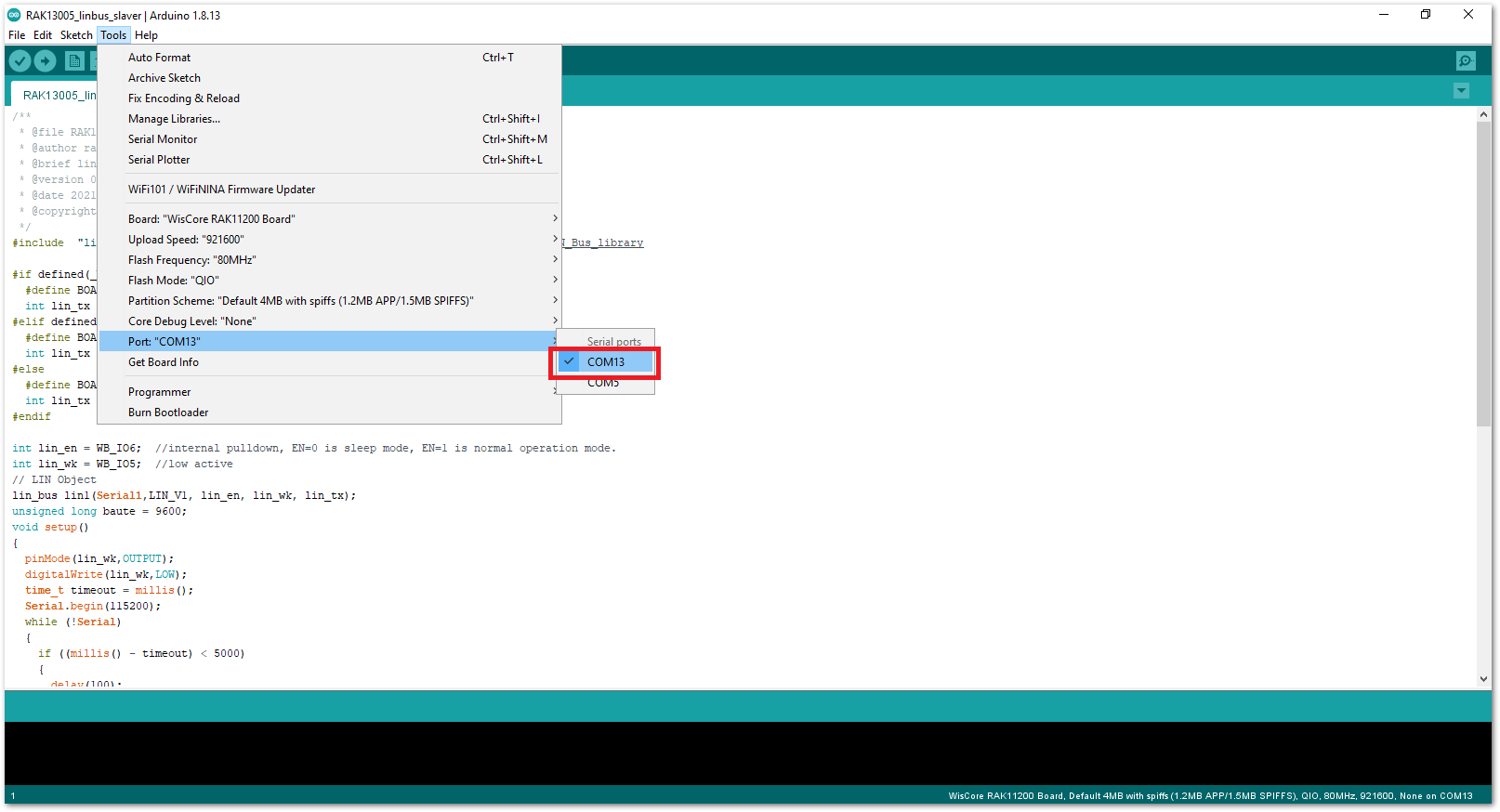 Figure 1: Select the Serial Port of RAK11200 for the RAK13005 LIN module in Peripheral mode.
RAK11200 requires the BOOT0 pin to be configured properly before uploading. If not done properly, uploading the source code to RAK11200 will fail. Check the full details on the RAK11200 Quick Start Guide.
- After ensuring the port matching the RAK13005 LIN Peripheral, you can now upload the
RAK13005_linbus_slavercode.
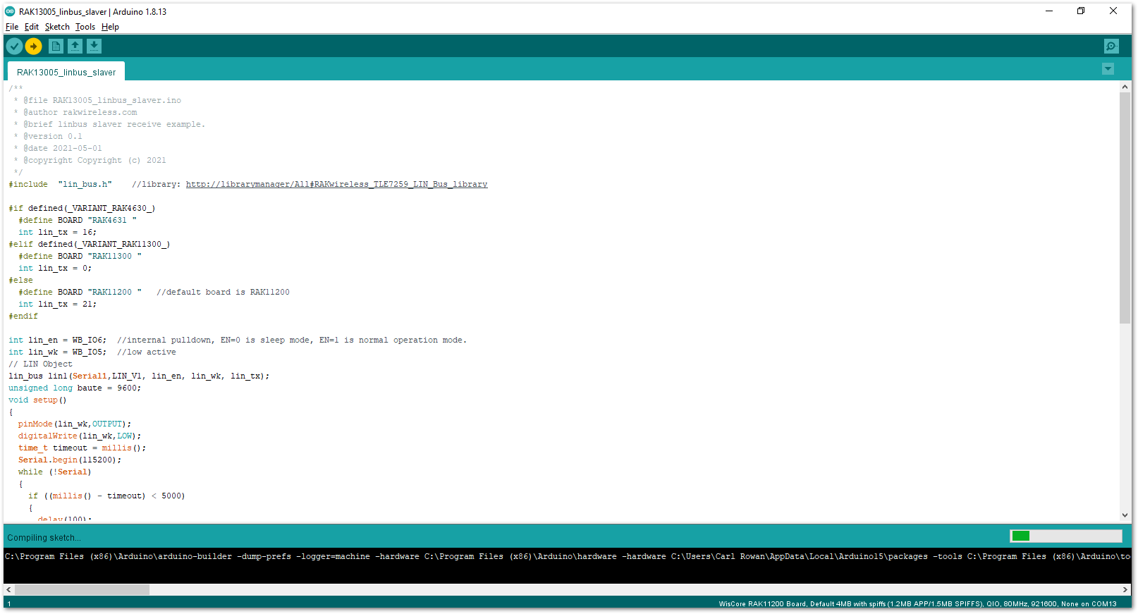 Figure 1: Uploading the RAK13005_linbus_slaver code
If you experience any error in compiling an example sketch, check the updated code for the RAK13005 WisBlock Core Module that can be found on the RAK13005 WisBlock Example Code Repository.
- Check Serial Monitor output.
- Check the Serial Monitor on the RAK13005 Peripheral device receiving the data coming from the RAK13005 Controller device. You must have the external power supply connected to have successful transmissions.
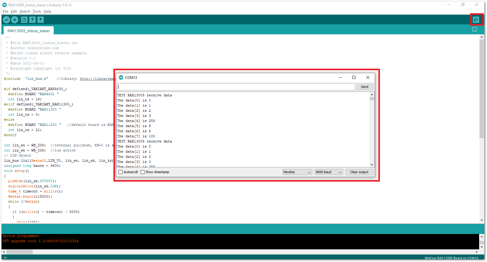 Figure 1: Serial Output of the RAK13005 Peripheral Mode
RAK13005 in RAK11310 WisBlock Core Guide
Arduino Setup
Figure 36 is an illustration on how to use two RAK13005 LIN modules for communication application. One RAK13005 is configured as Controller and the other RAK13005 is configured as Peripheral. The SMD resistors that set the mode are highlighted in a yellow box.
Figure 1: Two RAK13005 Interconnection for Controller and Peripheral mode- Select the RAK11300 WisBlock Core.
- Install the RAKwireless Arduino BSP to find the RAK11300 in the Arduino Boards Manager.
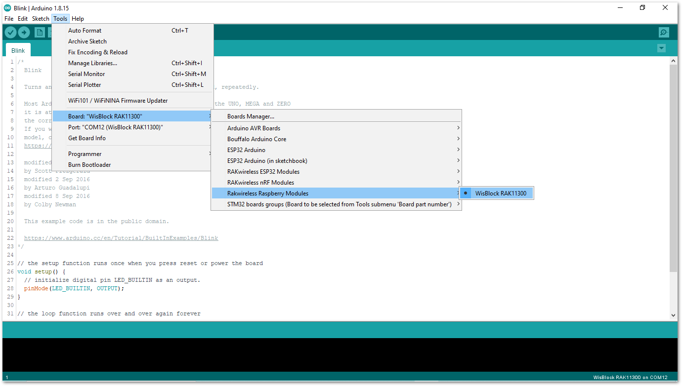 Figure 1: Selecting RAK11300 as WisBlock Core
- Next, install the RAKwireless TLE7259 library using Arduino Library manager.
- Select
Sketchfollowed byInclude LibrarythenManage Libraries.
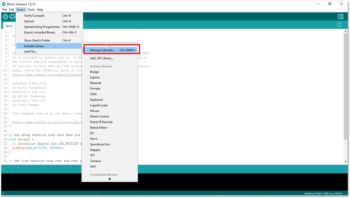 Figure 1: Open Arduino Library Manager
-
Search for RAKwireless TLE7259 on Library Manager text box.
-
Select the latest version of the library then click Install button.
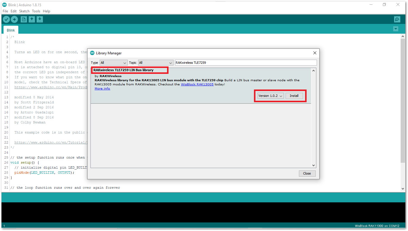 Figure 1: Look for RAKwireless TLE7259 LIN Bus Library
- After successful installation, close the Arduino Library window.
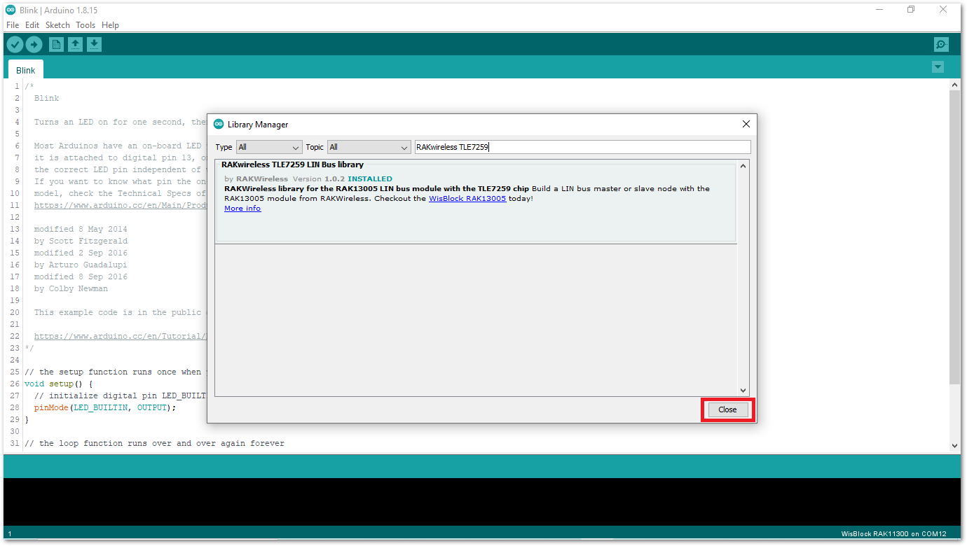 Figure 1: RAKwireless TLE7259 LIN Bus Library Successfully Installed
- Upload the
RAK13005_linbus_masterController sketch.
- Connect the first WisBlock with the RAK13005 module in Controller mode and select the
RAK13005_linbus_master.
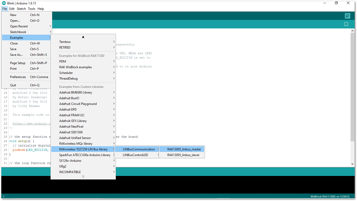 Figure 1: Open the code for the RAK13005 Controller
- Select the port where RAK11300 WisBlock Core is connected.
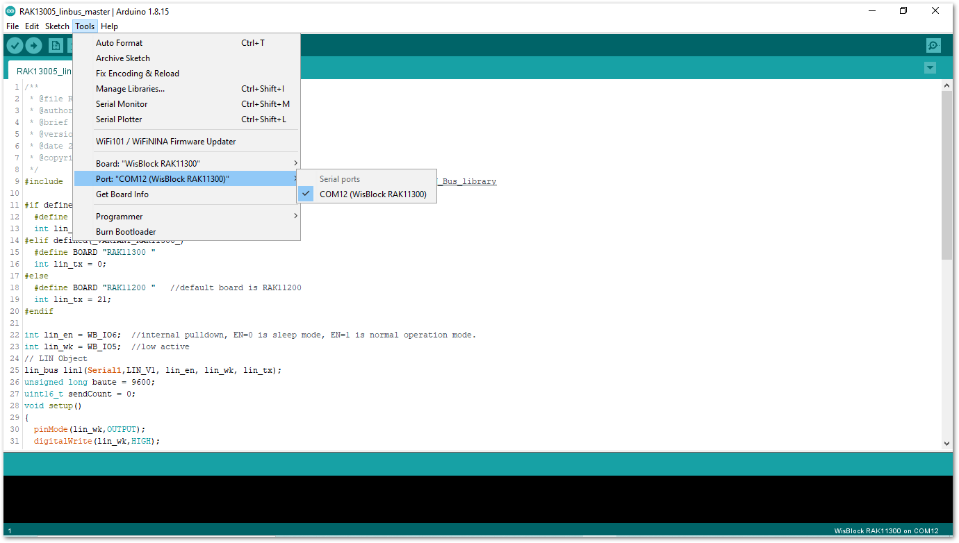 Figure 1: Select the Serial Port of RAK4631 for the RAK13005 LIN module in controller mode.
- Now, upload the
RAK13005_linbus_mastercode to the WisBlock Core.
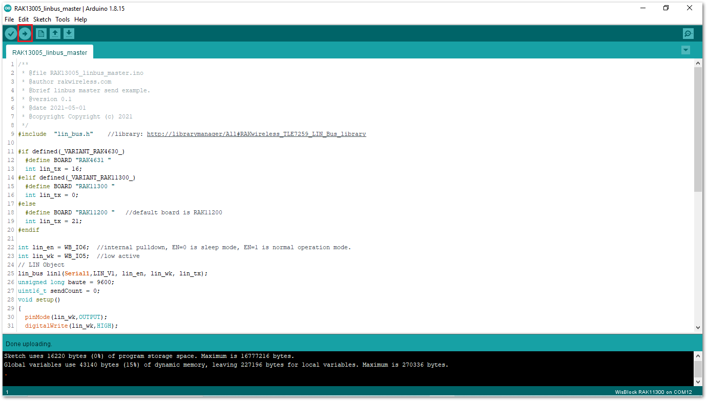 Figure 1: Successful code upload
- After the successful code upload, you can now open the Serial Monitor and see the Serial output.
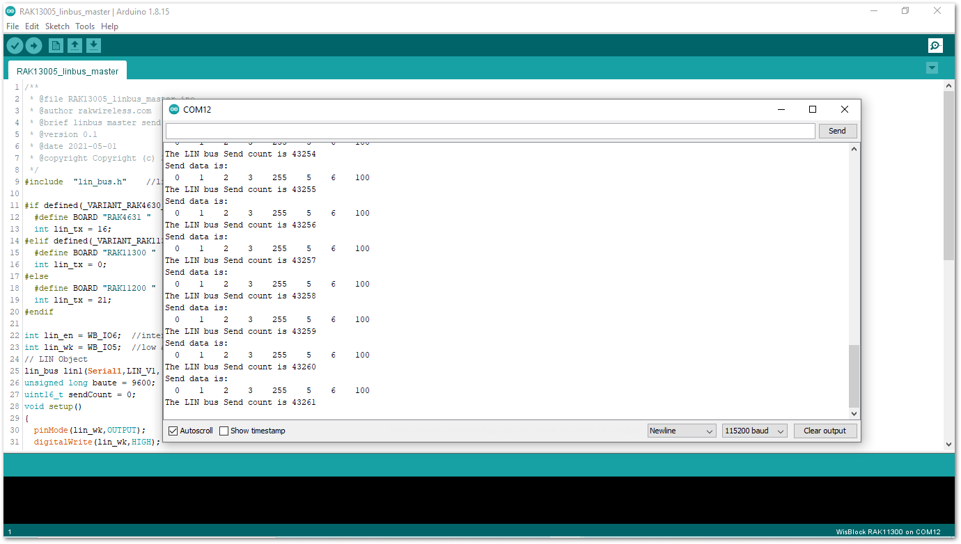 Figure 1: Serial Output of the RAK13005 Controller Mode
- Upload the
RAK13005_linbus_slaverPeripheral sketch.
- Connect the second WisBlock with the RAK13005 in Peripheral mode then select
RAK13005_linbus_slaver.
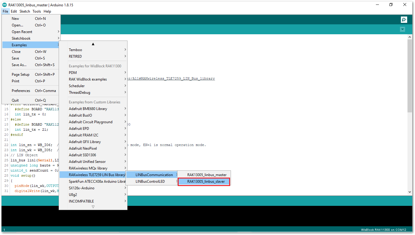 Figure 1: Open the code for the RAK13005 Peripheral
- Select the port, which is the additional port from the previous port for the controller. You should see two ports in your Arduino IDE.
Figure 1: Select the Serial Port of RAK11300 for the RAK13005 LIN module in peripheral mode.- After ensuring the port matching the RAK13005 LIN Peripheral, you can now upload the
RAK13005_linbus_slavercode.
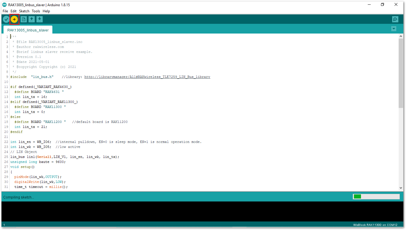 Figure 1: Uploading the RAK13005_linbus_slaver code
If you experience any error in compiling an example sketch, check the updated code for the RAK13005 WisBlock Core Module that can be found on the RAK13005 WisBlock Example Code Repository.
- Check Serial Monitor output.
- Check the Serial Monitor on the RAK13005 Peripheral device receiving the data coming from the RAK13005 Controller device. You must have the external power supply connected to have successful transmissions.
Figure 1: Serial Output of the RAK13005 Peripheral ModeTo extend the use of the RAKwireless TLE7259 LIN Bus library, check the TLE7259 Library methods.