RAK13300 as Transmitter
- You need to select RAK11200 as your WisBlock Core.
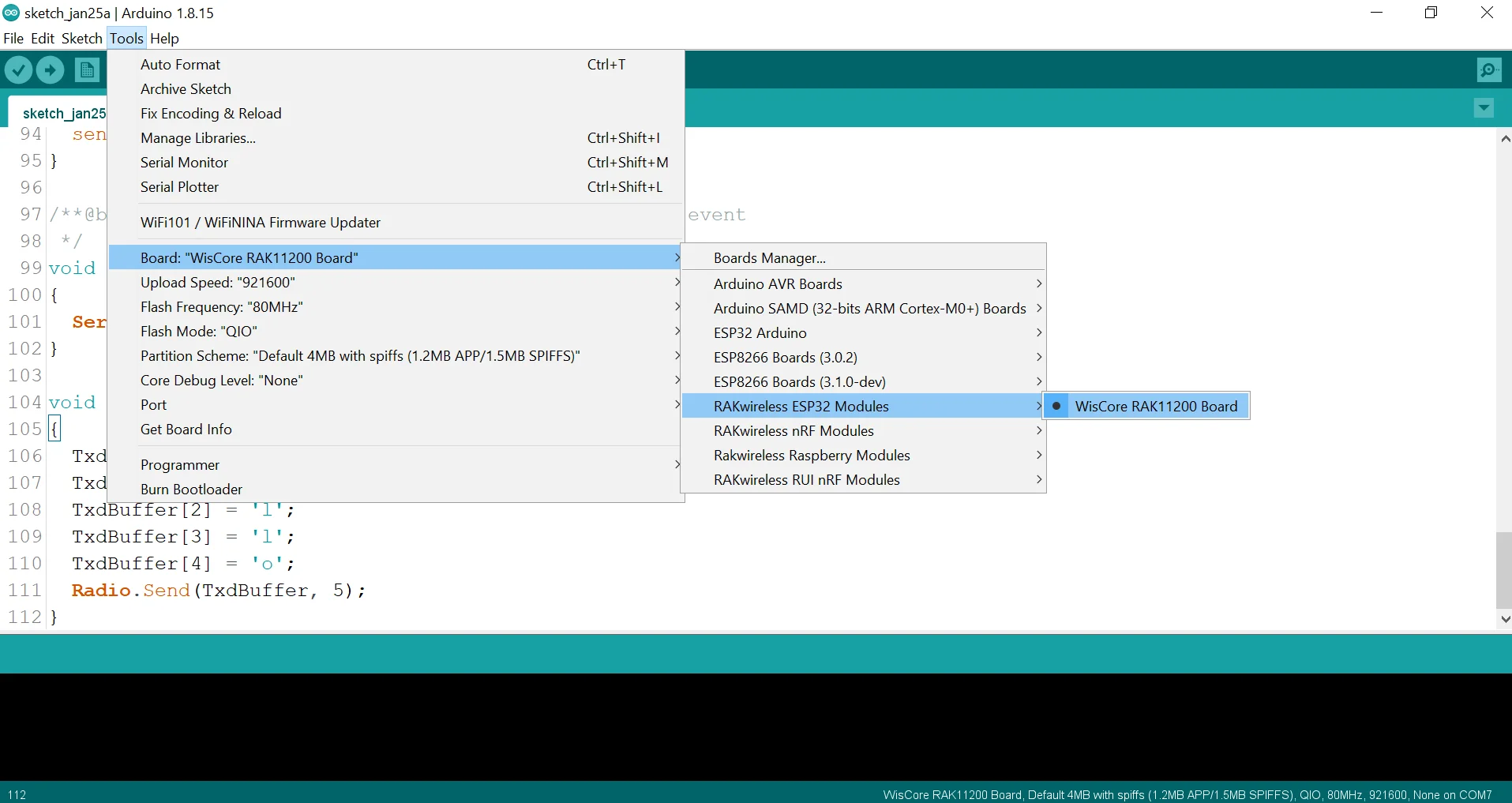 Figure 1: Selecting RAK11200 as WisBlock Core
- Next, copy the following sample code into your Arduino IDE:
Click to view the sample code.
/**
 * @file LoRaP2P_TX.ino
 * @author rakwireless.com
 * @brief Transmitter node for LoRa point to point communication
 * @version 0.1
 * @date 2021-08-21
 *
 * @copyright Copyright (c) 2020
 *
 */

#include <Arduino.h>
#include <SX126x-Arduino.h> //http://librarymanager/All#SX126x
#include <SPI.h>

// Function declarations
void OnTxDone(void);
void OnTxTimeout(void);


// Define LoRa parameters
#define RF_FREQUENCY 868300000  // Hz
#define TX_OUTPUT_POWER 22    // dBm
#define LORA_BANDWIDTH 0    // [0: 125 kHz, 1: 250 kHz, 2: 500 kHz, 3: Reserved]
#define LORA_SPREADING_FACTOR 7 // [SF7..SF12]
#define LORA_CODINGRATE 1   // [1: 4/5, 2: 4/6,  3: 4/7,  4: 4/8]
#define LORA_PREAMBLE_LENGTH 8  // Same for Tx and Rx
#define LORA_SYMBOL_TIMEOUT 0 // Symbols
#define LORA_FIX_LENGTH_PAYLOAD_ON false
#define LORA_IQ_INVERSION_ON false
#define RX_TIMEOUT_VALUE 3000
#define TX_TIMEOUT_VALUE 3000

static RadioEvents_t RadioEvents;
static uint8_t TxdBuffer[64];

void setup()
{
  pinMode(WB_IO2, OUTPUT);
    digitalWrite(WB_IO2, HIGH);
  // Initialize Serial for debug output
  time_t timeout = millis();
  Serial.begin(115200);
  while (!Serial)
  {
    if ((millis() - timeout) < 5000)
    {
            delay(100);
        }
        else
        {
            break;
        }
  }
  Serial.println("=====================================");
  Serial.println("LoRap2p Tx Test");
  Serial.println("=====================================");

  // Initialize the Radio callbacks
  RadioEvents.TxDone = OnTxDone;
  RadioEvents.RxDone = NULL;
  RadioEvents.TxTimeout = OnTxTimeout;
  RadioEvents.RxTimeout = NULL;
  RadioEvents.RxError = NULL;
  RadioEvents.CadDone = NULL;
  // Initialize LoRa chip.
  lora_rak13300_init();
  // Initialize the Radio
  Radio.Init(&RadioEvents);

  // Set Radio channel
  Radio.SetChannel(RF_FREQUENCY);

  // Set Radio TX configuration
  Radio.SetTxConfig(MODEM_LORA, TX_OUTPUT_POWER, 0, LORA_BANDWIDTH,
            LORA_SPREADING_FACTOR, LORA_CODINGRATE,
            LORA_PREAMBLE_LENGTH, LORA_FIX_LENGTH_PAYLOAD_ON,
            true, 0, 0, LORA_IQ_INVERSION_ON, TX_TIMEOUT_VALUE);
  send();
}

void loop()
{
  // Put your application tasks here, like reading of sensors,
  // Controlling actuators and/or other functions.
}

/**@brief Function to be executed on Radio Tx Done event
 */
void OnTxDone(void)
{
  Serial.println("OnTxDone");
  delay(5000);
  send();
}

/**@brief Function to be executed on Radio Tx Timeout event
 */
void OnTxTimeout(void)
{
  Serial.println("OnTxTimeout");
}

void send()
{
  TxdBuffer[0] = 'H';
  TxdBuffer[1] = 'e';
  TxdBuffer[2] = 'l';
  TxdBuffer[3] = 'l';
  TxdBuffer[4] = 'o';
  Radio.Send(TxdBuffer, 5);
}
- You can now select the right serial port and upload the code.
NOTE
Since you are using RAK11200 as WisBlock Core, you need to configure the BOOT0 pin before uploading. You need to short it to the ground then press the reset button of the WisBlock Base before releasing the BOOT0 pin. If not done properly, uploading the source code to RAK11200 will fail. Check the full details on the RAK11200 Quick Start Guide.
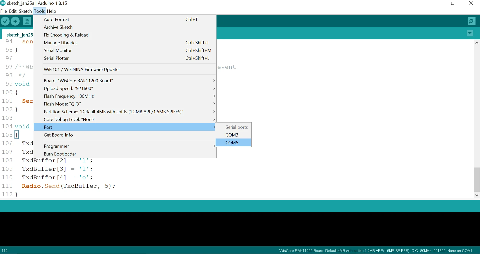 Figure 1: Selecting the correct Serial Port
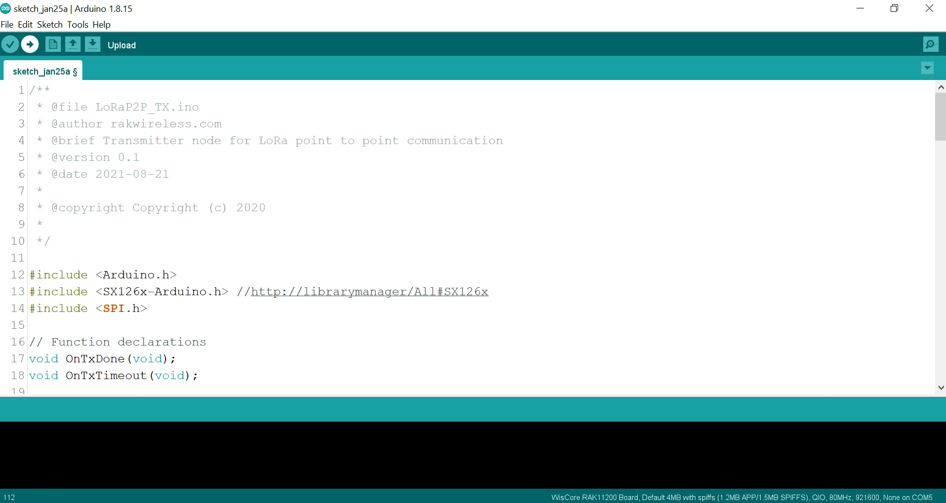 Figure 1: Uploading the RAK13300 example code
NOTE
If you experience any error in compiling the example sketch, check the updated code for the RAK13300 WisBlock LPWAN Wireless Module that can be found on the RAK13300 WisBlock Example Code Repository
- When you have successfully uploaded the example sketch, open the Serial Monitor of the Arduino IDE to see the transmission logs.
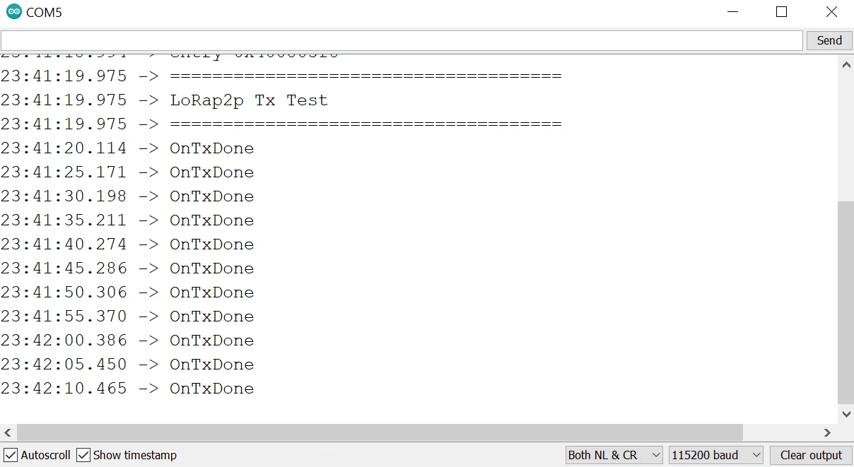 Figure 1: Transmission logs in Serial Monitor


