RAK13302 WisBlock LPWAN Wireless Module Quick Start Guide
Prerequisites
Before going through each and every step on using the RAK13302 WisBlock LPWAN Wireless Module, make sure to prepare the necessary items listed below:
Hardware
- RAK13302
- Your choice of WisBlock Base
- RAK11200 WisBlock Core
- RAK3401 WisBlock Core (Only available as WisMesh 1W Booster Starter Kit)
- USB Cable
- LoRa-compatible Antennas
- Li-Ion/LiPo battery (optional)
- Solar charger (optional)
The RAK13302 can only be used with the WisBlock Core modules RAK3401 or RAK11200. Other WisBlock Core modules already have an integrated LoRa transceiver.
Software
- Download and install the Arduino IDE.
- To add the RAKwireless Core boards on your Arduino board, install the RAKwireless Arduino BSP. Follow the steps in the GitHub repo.
Product Configuration
Hardware Setup
You can integrate the RAK13302 Wireless module on WisBlock Core module that do not have a built-in LoRa radio chip like the WisBlock Core RAK3401 or RAK11200. The RAK13302 module will extend your WisBlock application to have LoRa P2P or LoRaWAN functionality. For more information about RAK13302, refer to its Datasheet.
RAK13302 module can be mounted to the IO slot of the WisBlock Base and communicated to the WisBlock Core via SPI. The module is activated via WB_IO2 pin of the WisBlock Core.
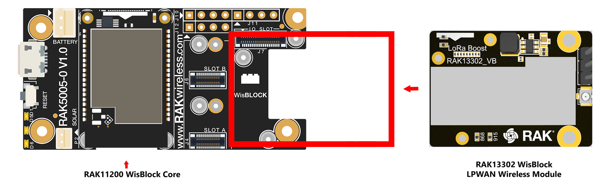 Figure 1: RAK13302 connection to WisBlock Base
Assemble WisBlock Modules
As shown in Figure 2, the location of the IO Slot is properly marked by silkscreen. Follow carefully the procedure defined in RAK5005-O module assembly/disassembly instructions to attach a WisBlock module. Once attached, carefully fix the module with one or more pieces of M1.2 x 3 mm screws depending on the module.
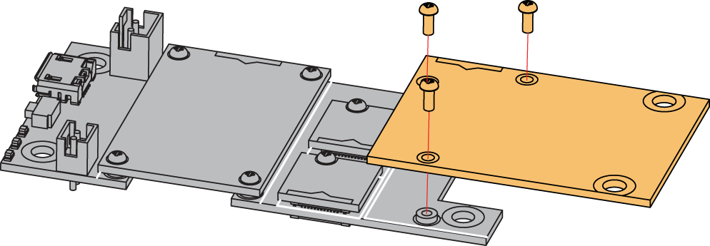 Figure 1: RAK13302 Wireless Module mounting mechanism
Disassemble WisBlock Modules
The procedure in disassembling any type of WisBlock modules is the same.
- First, remove the screws.
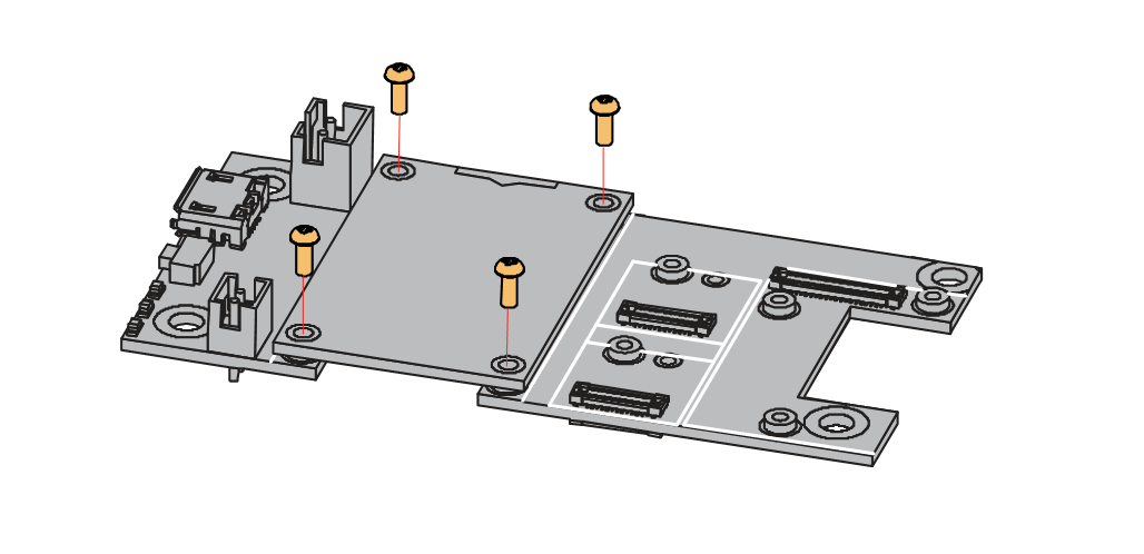 Figure 1: Remove screws from the WisBlock module
- Once the screws are removed, check the silkscreen of the module to find the correct location where force can be applied.
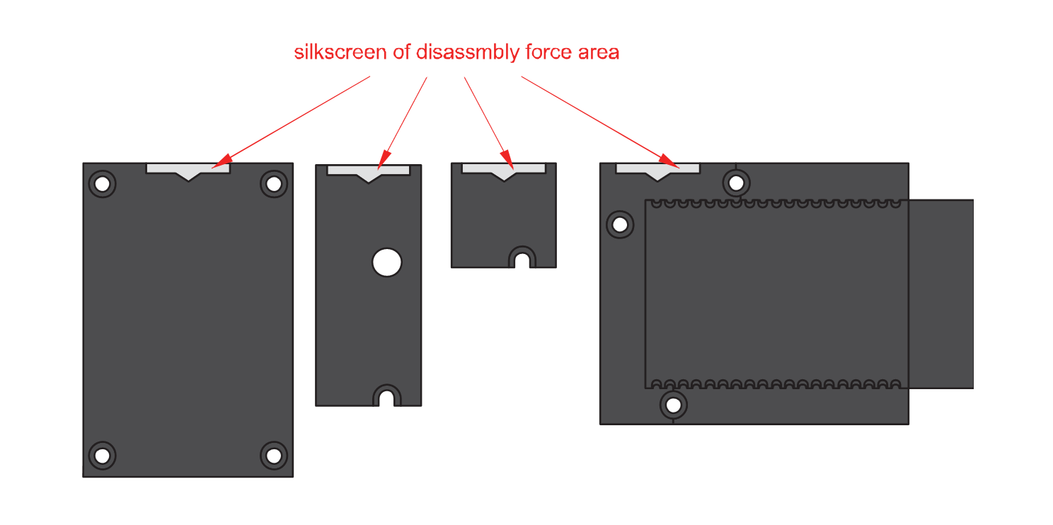 Figure 1: Detach silkscreen on the WisBlock module
- Apply force to the module at the position of the connector, as shown in Figure 5, to detach the module from the base board.
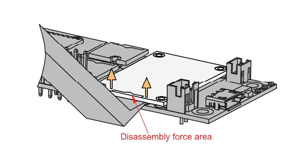 Figure 1: Apply even forces on the proper location of a WisBlock module
If you will connect other modules to the remaining WisBlock Base slots, check on the WisBlock Pin Mapper tool for possible conflicts. RAK13302 uses UART communication lines, and it can cause possible conflict, especially on some modules that also use UART.
LoRa Antenna
The RAK13302 requires a LoRa Antenna to have a good signal. Do not power the module without an antenna connected to the IPEX connector, as this can damage the RF section of the chip.
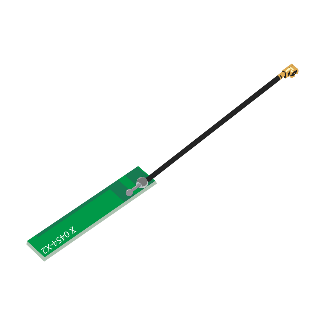 Figure 1: LoRa Antenna
Detailed information about the LoRa antenna can be found on the LoRa Antenna Datasheet.
RAK13302 has the antenna slot which can be found in Figure 7.
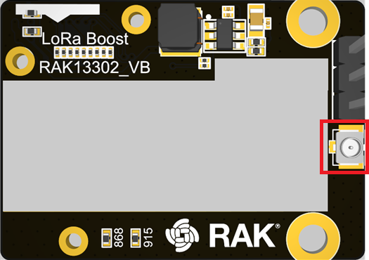 Figure 1: RAK13302 Antenna Slot
To avoid damage, always connect an antenna when using LoRa transceivers. Use screws to keep the module firmly in place for proper operation.
Power Selector Jumper
You have multiple options to power the device:
- With jumper set to internal
- USB + Li-Ion battery (3.7 V)
- Solar + Li-Ion battery (3.7 V)
- 5 V through solar connector + Li-Ion battery (3.7 V)
- This setting requires always a battery connected to provide the required power.
- With jumper set to external
- 5 VDC supply with 1.5 A through connector on the RAK13302. This will supply the whole setup, Base Board, Core module and 1W transceiver. It will as well charge a battery if connected.
Due to the high power consumption during the 1W LoRa transmission the device has to be powered either by battery or by an external 5V supply to work correct.
The 3-pin jumper header is to select the supply source for the booster chip.
| Jumper Position | Supply Source |
|---|---|
| IN_5V to 5 V | Supply from WisBlock Base Board Battery |
| EX_5V to 5 V | Supply from Jx connector |
If the supply is through EX_5V, the whole WisBlock Base Board can be supplied through this source.
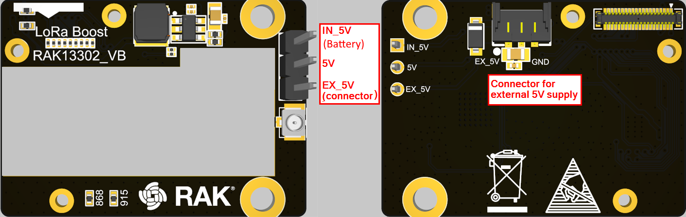 Figure 1: RAK13302 5 V supply selection
External power supply cable connections:
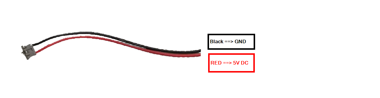 Figure 1: RAK13302 5 V supply selection
Battery Connection
If not using the external 5V supply for the module, it is required to use a Li-Ion/LiPo battery via connectors, as shown in Figure 8. This illustration shows RAK5005-O as WisBlock Base. There are other WisBlock Base boards available, and you need to check the datasheet of the specific WisBlock Base board for the right polarity and parameters.
 Figure 1: WisBlock Base RAK5005-O battery polarity and connection
- Batteries can cause harm if not handled properly.
- Only 3.7-4.2 V Rechargeable LiPo batteries are supported. It is highly recommended not to use other types of batteries with the system unless you know what you are doing.
- If a non-rechargeable battery is used, it has to be unplugged first before connecting the USB cable to the USB port of the board to configure the device. Not doing so might damage the battery or cause a fire.
- Only 5 V solar panels are supported. Do not use 12 V solar panels. It will destroy the charging unit and eventually other electronic parts.
- Make sure the battery wires match the polarity on the WisBlock Base board. Not all batteries have the same wiring.
Software Configuration and Example
The RAK13302 is a LoRa module based on the SX1262 LoRa chip. It provides an easy-to-use, small-size, and low-power solution for long-range wireless data applications.
LoRa Point-to-Point Example
In this example code, you will be able to send/receive payloads via LoRaP2P using the RAK13302 LPWAN Wireless Module. This will ensure that your RAK13302 is functional and ready for your IoT project.
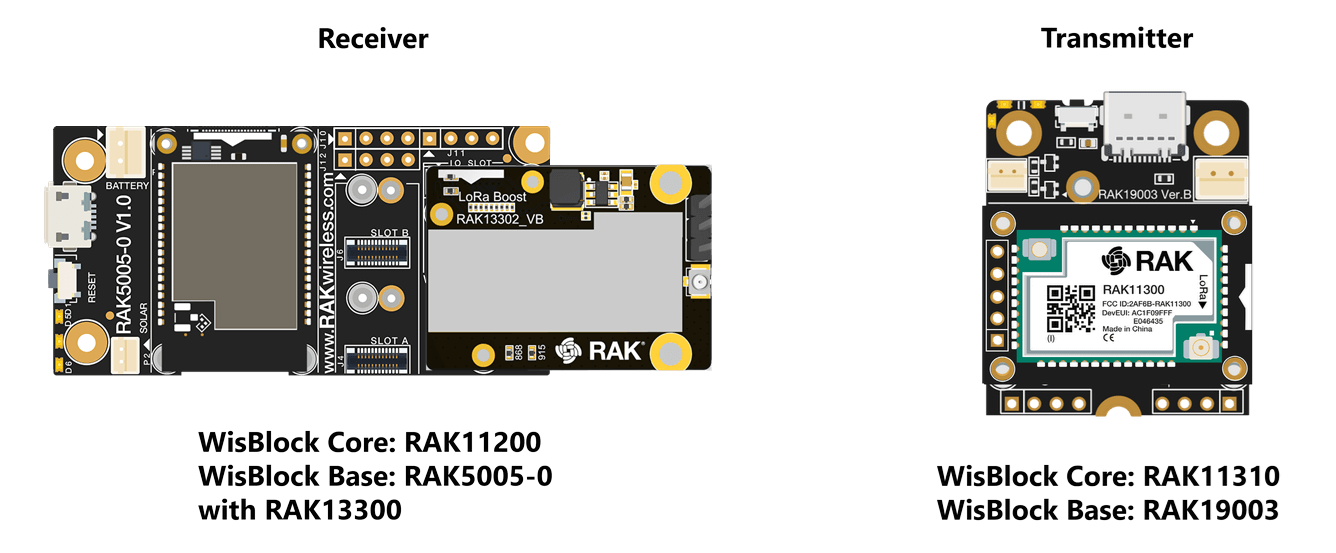 Figure 1: LoRaP2P Example
You can use other WisBlock Base and WisBlock Core with LoRa capability as dummy transmitter.
Set Up RAK13302 as the Receiver with the RAK3401
If you have already installed the RAKwireless Arduino BSP, the WisBlock Core and example code should now be available on the Arduino IDE.
- If using the RAK3401, you need to select RAK4630 as your WisBlock Core, as shown in Figure 10.
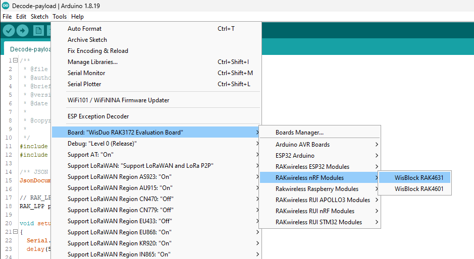 Figure 1: Select RAK4631 as WisBlock Core
The RAK3401 is not listed as separate board in the BSP. Choose RAK13302 to compile code for the RAK3401 since it is compatible with the RAK4631.
- Next, copy the following sample code into your Arduino IDE:
Click to view the sample code.
	/**
 * @file LoRaP2P_RX.ino
 * @author rakwireless.com
 * @brief Receiver node for LoRa point to point communication
 * @version 0.1
 * @date 2026-01-27
 *
 * @copyright Copyright (c) 2020
 *
 */
#include <Arduino.h>
#include <SX126x-Arduino.h> //http://librarymanager/All#SX126x
#include <SPI.h>

// Function declarations
void OnRxDone(uint8_t *payload, uint16_t size, int16_t rssi, int8_t snr);
void OnRxTimeout(void);
void OnRxError(void);


// Define LoRa parameters
#define RF_FREQUENCY 868300000	// Hz
#define TX_OUTPUT_POWER 22		// dBm
#define LORA_BANDWIDTH 0		// [0: 125 kHz, 1: 250 kHz, 2: 500 kHz, 3: Reserved]
#define LORA_SPREADING_FACTOR 7 // [SF7..SF12]
#define LORA_CODINGRATE 1		// [1: 4/5, 2: 4/6,  3: 4/7,  4: 4/8]
#define LORA_PREAMBLE_LENGTH 8	// Same for Tx and Rx
#define LORA_SYMBOL_TIMEOUT 0	// Symbols
#define LORA_FIX_LENGTH_PAYLOAD_ON false
#define LORA_IQ_INVERSION_ON false
#define RX_TIMEOUT_VALUE 3000
#define TX_TIMEOUT_VALUE 3000

static RadioEvents_t RadioEvents;

static uint8_t RcvBuffer[64];

void setup()
{
    pinMode(WB_IO2, OUTPUT);
    digitalWrite(WB_IO2, HIGH);
	// Initialize Serial for debug output
	time_t timeout = millis();
	Serial.begin(115200);
	while (!Serial)
	{
		if ((millis() - timeout) < 5000)
		{
            delay(100);
        }
        else
        {
            break;
        }
	}
	Serial.println("=====================================");
	Serial.println("LoRaP2P Rx Test");
	Serial.println("=====================================");

	// Initialize the Radio callbacks
	RadioEvents.TxDone = NULL;
	RadioEvents.RxDone = OnRxDone;
	RadioEvents.TxTimeout = NULL;
	RadioEvents.RxTimeout = OnRxTimeout;
	RadioEvents.RxError = OnRxError;
	RadioEvents.CadDone = NULL;
	// Initialize LoRa chip.
	lora_rak3400_init();
	// Initialize the Radio
	Radio.Init(&RadioEvents);

	// Set Radio channel
	Radio.SetChannel(RF_FREQUENCY);

	// Set Radio RX configuration
	Radio.SetRxConfig(MODEM_LORA, LORA_BANDWIDTH, LORA_SPREADING_FACTOR,
					  LORA_CODINGRATE, 0, LORA_PREAMBLE_LENGTH,
					  LORA_SYMBOL_TIMEOUT, LORA_FIX_LENGTH_PAYLOAD_ON,
					  0, true, 0, 0, LORA_IQ_INVERSION_ON, true);

	// Start LoRa
	Serial.println("Starting Radio.Rx");
	Radio.Rx(RX_TIMEOUT_VALUE);
}

void loop()
{
 // Put your application tasks here, like reading of sensors,
  // Controlling actuators and/or other functions.

}

/**@brief Function to be executed on Radio Rx Done event
 */
void OnRxDone(uint8_t *payload, uint16_t size, int16_t rssi, int8_t snr)
{
  Serial.println("OnRxDone");
  delay(10);
  memcpy(RcvBuffer, payload, size);

  Serial.printf("RssiValue=%d dBm, SnrValue=%d\n", rssi, snr);

  for (int idx = 0; idx < size; idx++)
  {
    Serial.printf("%02X ", RcvBuffer[idx]);
  }
  Serial.println("");
  Radio.Rx(RX_TIMEOUT_VALUE);
}

/**@brief Function to be executed on Radio Rx Timeout event
 */
void OnRxTimeout(void)
{
  Serial.println("OnRxTimeout");
  Radio.Rx(RX_TIMEOUT_VALUE);
}

/**@brief Function to be executed on Radio Rx Error event
 */
void OnRxError(void)
{
  Serial.println("OnRxError");
  Radio.Rx(RX_TIMEOUT_VALUE);
}
- You can now select the right serial port and upload the code, as shown in Figure 11 and Figure 12.
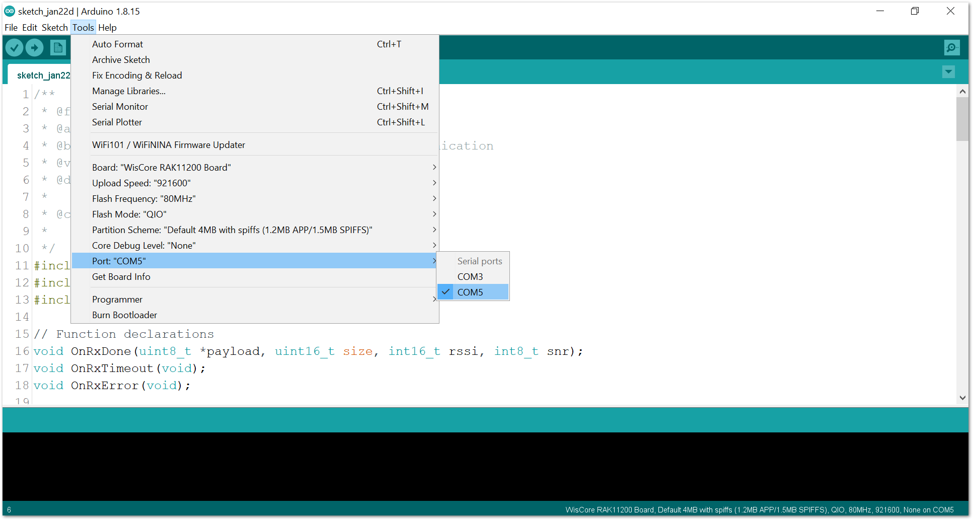 Figure 1: Select the correct Serial Port
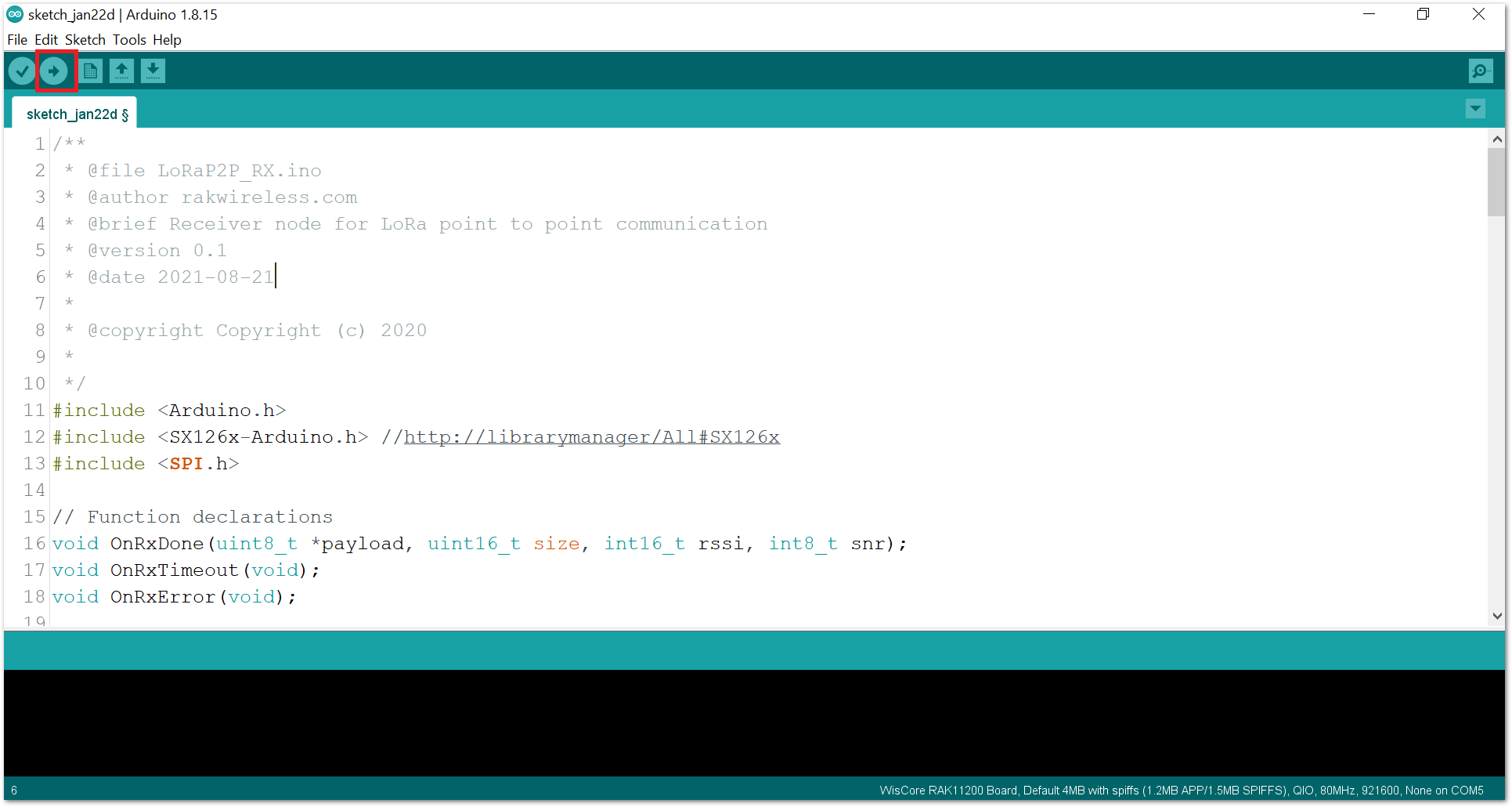 Figure 1: Upload the RAK13302 example code
If you experience any error in compiling the example sketch, make sure that you have the latest version of the SX126x-Arduino library installed. The RAK13302 is supported by library versions V2.0.32 or newer.
- When you successfully uploaded the example sketch, open the Serial Monitor of the Arduino IDE to see the initial logs. You may not see any logs yet if you have not set the transmitter up or you do not have any existing transmitting device.
Set Up RAK13302 as the Receiver with the RAK11200
If you have already installed the RAKwireless Arduino BSP, the WisBlock Core and example code should now be available on the Arduino IDE.
- If using the RAK11200, you need to select RAK11200 as your WisBlock Core, as shown in Figure 10.
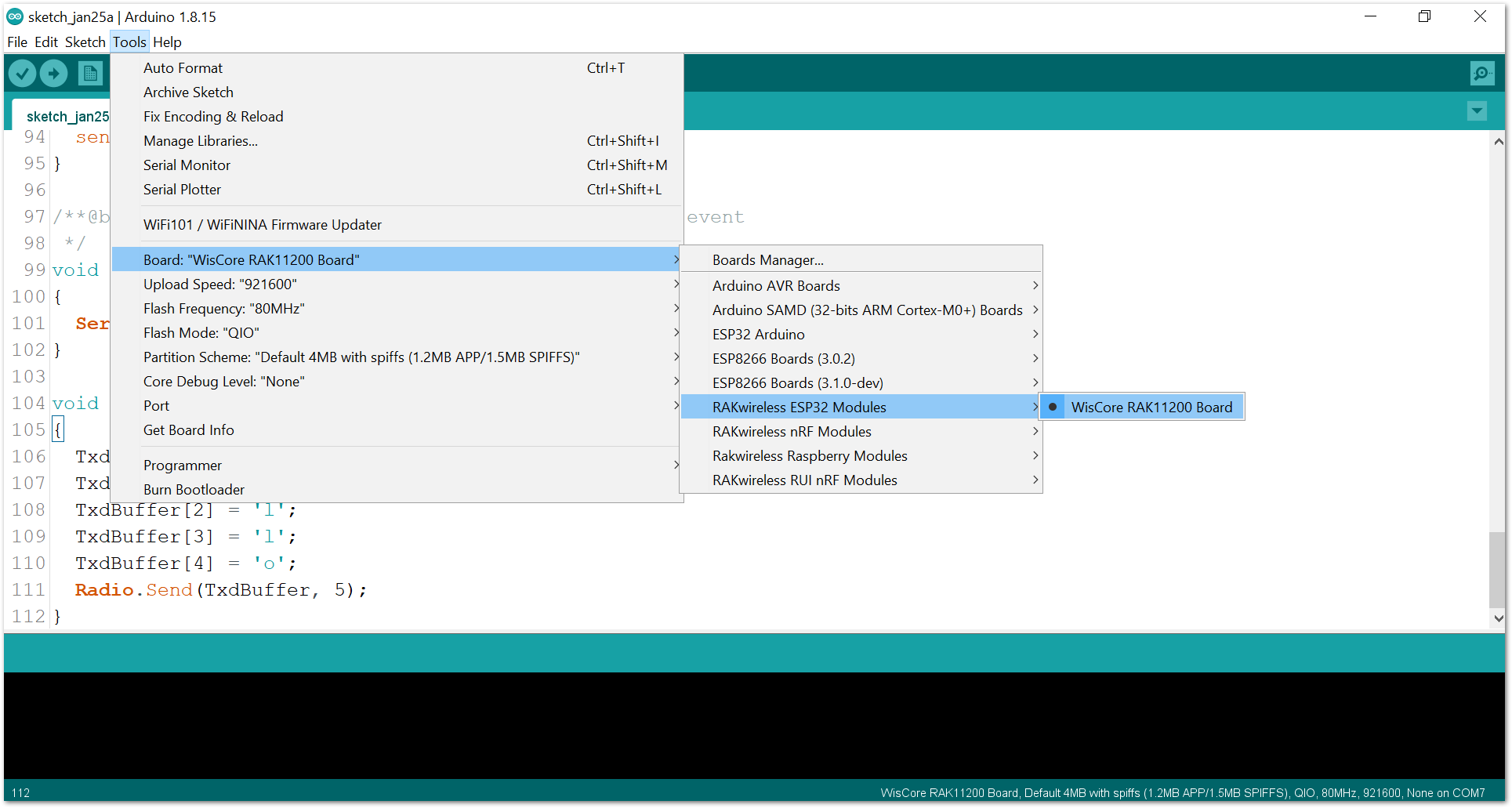 Figure 1: Select RAK11200 as WisBlock Core
- Next, copy the following sample code into your Arduino IDE:
Click to view the sample code.
	/**
 * @file LoRaP2P_RX.ino
 * @author rakwireless.com
 * @brief Receiver node for LoRa point to point communication
 * @version 0.1
 * @date 2021-08-21
 *
 * @copyright Copyright (c) 2020
 *
 */
#include <Arduino.h>
#include <SX126x-Arduino.h> //http://librarymanager/All#SX126x
#include <SPI.h>

// Function declarations
void OnRxDone(uint8_t *payload, uint16_t size, int16_t rssi, int8_t snr);
void OnRxTimeout(void);
void OnRxError(void);


// Define LoRa parameters
#define RF_FREQUENCY 868300000	// Hz
#define TX_OUTPUT_POWER 22		// dBm
#define LORA_BANDWIDTH 0		// [0: 125 kHz, 1: 250 kHz, 2: 500 kHz, 3: Reserved]
#define LORA_SPREADING_FACTOR 7 // [SF7..SF12]
#define LORA_CODINGRATE 1		// [1: 4/5, 2: 4/6,  3: 4/7,  4: 4/8]
#define LORA_PREAMBLE_LENGTH 8	// Same for Tx and Rx
#define LORA_SYMBOL_TIMEOUT 0	// Symbols
#define LORA_FIX_LENGTH_PAYLOAD_ON false
#define LORA_IQ_INVERSION_ON false
#define RX_TIMEOUT_VALUE 3000
#define TX_TIMEOUT_VALUE 3000

static RadioEvents_t RadioEvents;

static uint8_t RcvBuffer[64];

void setup()
{
    pinMode(WB_IO2, OUTPUT);
    digitalWrite(WB_IO2, HIGH);
	// Initialize Serial for debug output
	time_t timeout = millis();
	Serial.begin(115200);
	while (!Serial)
	{
		if ((millis() - timeout) < 5000)
		{
            delay(100);
        }
        else
        {
            break;
        }
	}
	Serial.println("=====================================");
	Serial.println("LoRaP2P Rx Test");
	Serial.println("=====================================");

	// Initialize the Radio callbacks
	RadioEvents.TxDone = NULL;
	RadioEvents.RxDone = OnRxDone;
	RadioEvents.TxTimeout = NULL;
	RadioEvents.RxTimeout = OnRxTimeout;
	RadioEvents.RxError = OnRxError;
	RadioEvents.CadDone = NULL;
	// Initialize LoRa chip.
	lora_rak13300_init();
	// Initialize the Radio
	Radio.Init(&RadioEvents);

	// Set Radio channel
	Radio.SetChannel(RF_FREQUENCY);

	// Set Radio RX configuration
	Radio.SetRxConfig(MODEM_LORA, LORA_BANDWIDTH, LORA_SPREADING_FACTOR,
					  LORA_CODINGRATE, 0, LORA_PREAMBLE_LENGTH,
					  LORA_SYMBOL_TIMEOUT, LORA_FIX_LENGTH_PAYLOAD_ON,
					  0, true, 0, 0, LORA_IQ_INVERSION_ON, true);

	// Start LoRa
	Serial.println("Starting Radio.Rx");
	Radio.Rx(RX_TIMEOUT_VALUE);
}

void loop()
{
 // Put your application tasks here, like reading of sensors,
  // Controlling actuators and/or other functions.

}

/**@brief Function to be executed on Radio Rx Done event
 */
void OnRxDone(uint8_t *payload, uint16_t size, int16_t rssi, int8_t snr)
{
  Serial.println("OnRxDone");
  delay(10);
  memcpy(RcvBuffer, payload, size);

  Serial.printf("RssiValue=%d dBm, SnrValue=%d\n", rssi, snr);

  for (int idx = 0; idx < size; idx++)
  {
    Serial.printf("%02X ", RcvBuffer[idx]);
  }
  Serial.println("");
  Radio.Rx(RX_TIMEOUT_VALUE);
}

/**@brief Function to be executed on Radio Rx Timeout event
 */
void OnRxTimeout(void)
{
  Serial.println("OnRxTimeout");
  Radio.Rx(RX_TIMEOUT_VALUE);
}

/**@brief Function to be executed on Radio Rx Error event
 */
void OnRxError(void)
{
  Serial.println("OnRxError");
  Radio.Rx(RX_TIMEOUT_VALUE);
}
- You can now select the right serial port and upload the code, as shown in Figure 11 and Figure 12.
Since you are using RAK11200 as WisBlock Core, you need to configure the BOOT0 pin before uploading. You need to short it to the ground then press the reset button of the WisBlock Base before releasing the BOOT0 pin. If not done properly, uploading the source code to RAK11200 will fail. Check the full details on the RAK11200 Quick Start Guide.
Figure 1: Select the correct Serial PortFigure 1: Upload the RAK13302 example codeIf you experience any error in compiling the example sketch, check the updated code for the RAK13302 WisBlock LPWAN Wireless Module that can be found on the RAK13302 WisBlock Example Code Repository.
Make as well sure that you have the latest version of the SX126x-Arduino library installed. The RAK13302 is supported by library versions V2.0.32 or newer.
- When you successfully uploaded the example sketch, open the Serial Monitor of the Arduino IDE to see the initial logs. You may not see any logs yet if you have not set the transmitter up or you do not have any existing transmitting device.
Set Up a Dummy Transmitter
In this example, you will use RAK11310 as the WisBlock Core and RAK19003 as the WisBlock Base for the dummy transmitter.
- You need to select RAK11300 as your WisBlock Core, as shown in Figure 13.
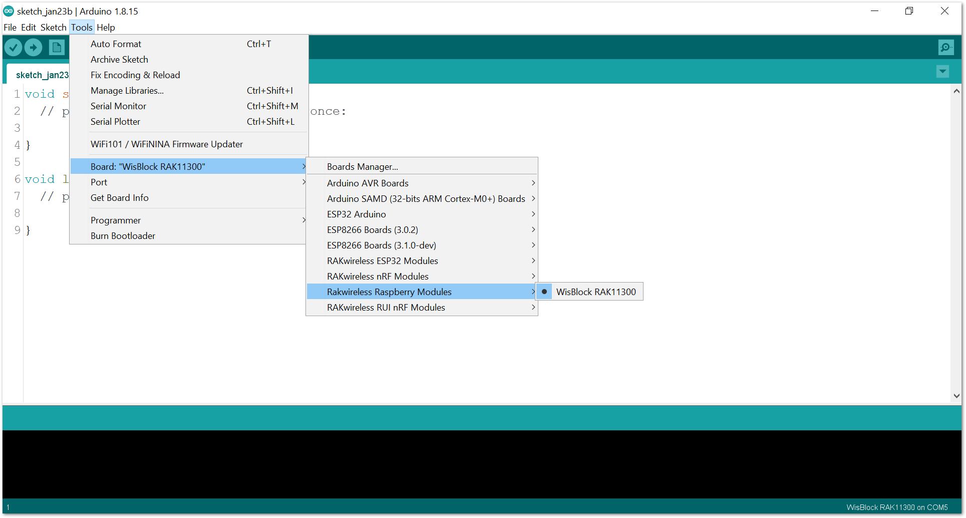 Figure 1: Select RAK11300 as WisBlock Core
- Open the example code for LoRaP2P Transmitter, as shown in Figure 14.
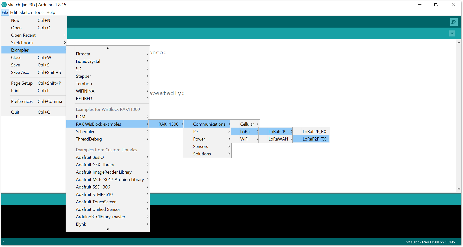 Figure 1: Open the example code
- Select the correct port and upload, as shown in Figure 15 and Figure 16.
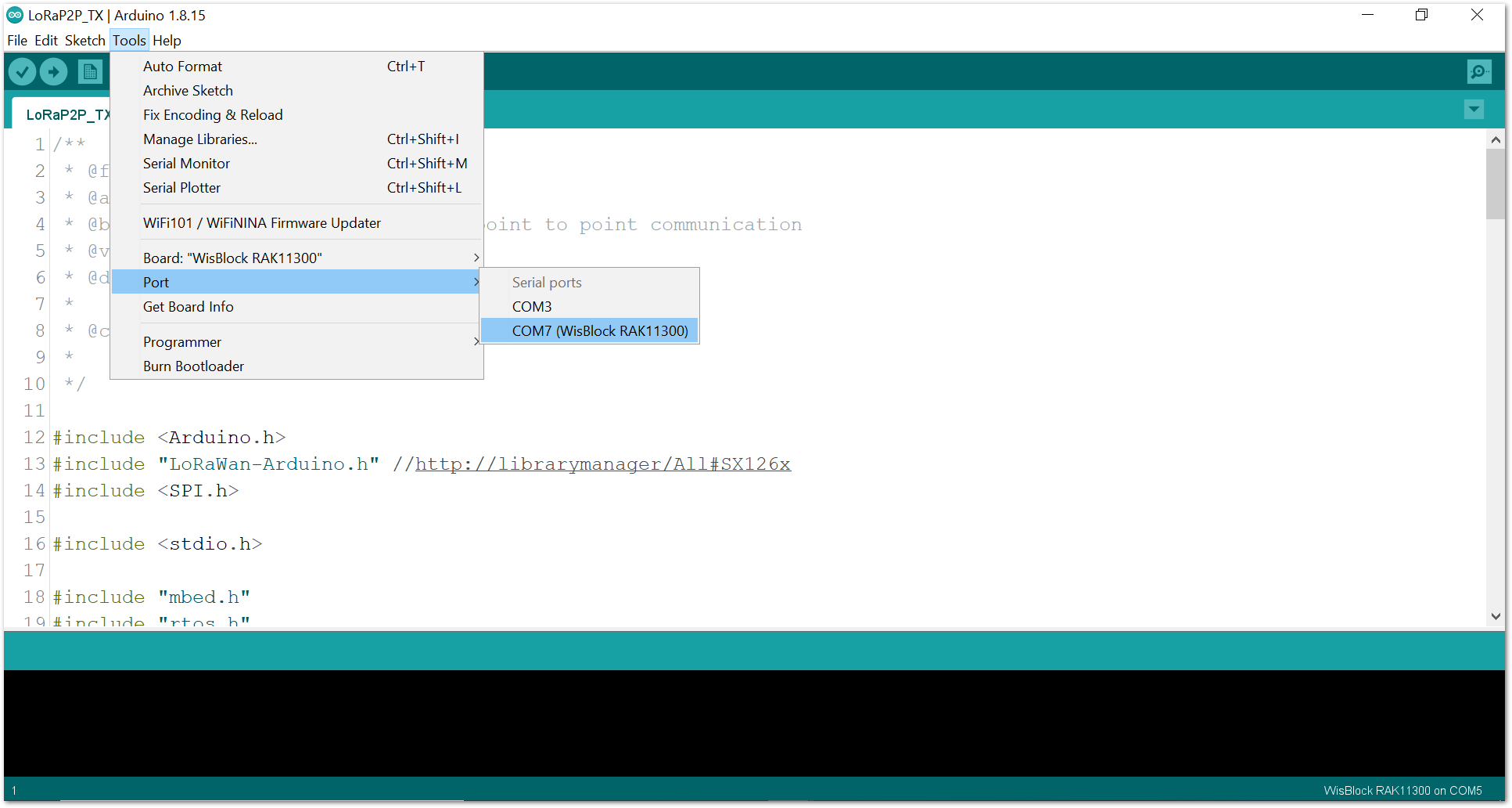 Figure 1: Select the correct serial port
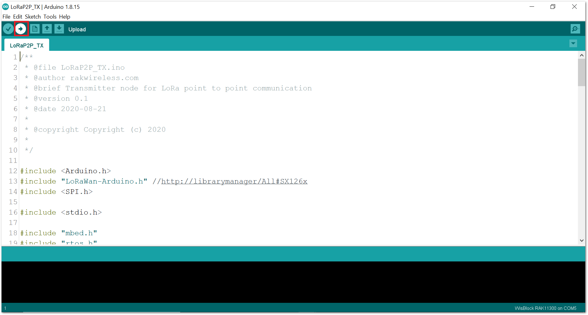 Figure 1: Upload the code
- When you have successfully uploaded the example sketch, open the Serial Monitor of the Arduino IDE to see the initial logs, as shown in Figure 17.
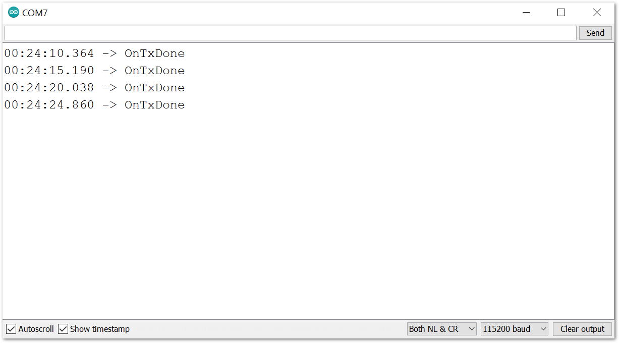 Figure 1: Transmission logs in Serial Monitor
OnTxDone respond means that your transmitter is now ready.
Test the Receive and Transmit Transaction
- To check if the communication is successful, you can power the transmitting node via battery or power brick to avoid confusion in the serial port. You may refer to Figure 18 for the illustration.
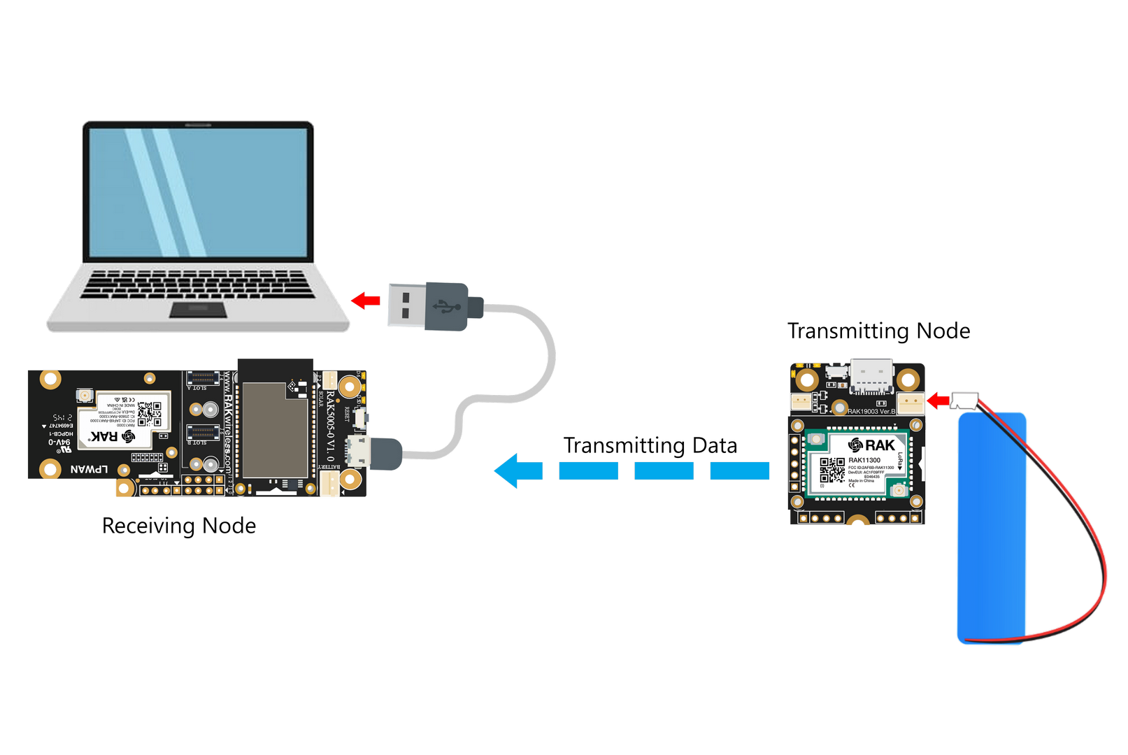 Figure 1: Receive and Transmit Node Setup
- Connect the receiving node to your PC and open the serial monitor. You will see the message is received, as shown in Figure 19.
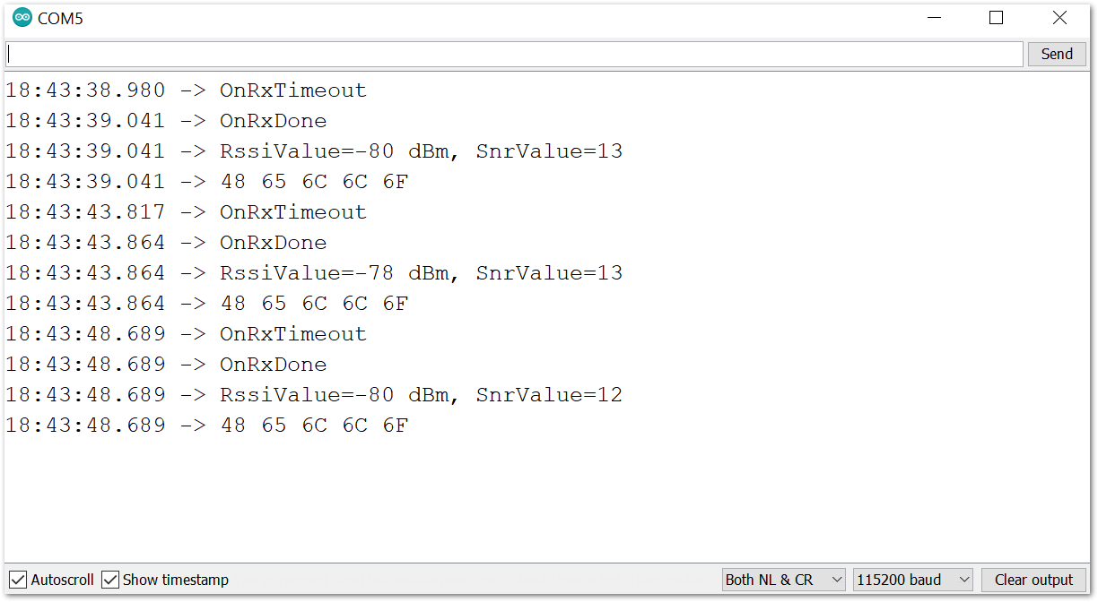 Figure 1: Payload logs received in Serial Monitor
Set Up RAK13302 as the Transmitter with the RAK3401
If you have already installed the RAKwireless Arduino BSP, the WisBlock Core and example code should now be available on the Arduino IDE.
- If using the RAK3401, you need to select RAK4631 as your WisBlock Core, as shown in Figure 20.
Figure 1: Select RAK3401 as WisBlock CoreThe RAK3401 is not listed as separate board in the BSP. Choose RAK13302 to compile code for the RAK3401 since it is compatible with the RAK4631.
- Next, copy the following sample code into your Arduino IDE:
Click to view the sample code.
/**
 * @file LoRaP2P_TX.ino
 * @author rakwireless.com
 * @brief Transmitter node for LoRa point to point communication
 * @version 0.1
 * @date 2026-01-27
 *
 * @copyright Copyright (c) 2026
 *
 */

#include <Arduino.h>
#include <SX126x-Arduino.h> //http://librarymanager/All#SX126x
#include <SPI.h>

// Function declarations
void OnTxDone(void);
void OnTxTimeout(void);


// Define LoRa parameters
#define RF_FREQUENCY 868300000  // Hz
#define TX_OUTPUT_POWER 22    // dBm
#define LORA_BANDWIDTH 0    // [0: 125 kHz, 1: 250 kHz, 2: 500 kHz, 3: Reserved]
#define LORA_SPREADING_FACTOR 7 // [SF7..SF12]
#define LORA_CODINGRATE 1   // [1: 4/5, 2: 4/6,  3: 4/7,  4: 4/8]
#define LORA_PREAMBLE_LENGTH 8  // Same for Tx and Rx
#define LORA_SYMBOL_TIMEOUT 0 // Symbols
#define LORA_FIX_LENGTH_PAYLOAD_ON false
#define LORA_IQ_INVERSION_ON false
#define RX_TIMEOUT_VALUE 3000
#define TX_TIMEOUT_VALUE 3000

static RadioEvents_t RadioEvents;
static uint8_t TxdBuffer[64];

void setup()
{
  pinMode(WB_IO2, OUTPUT);
    digitalWrite(WB_IO2, HIGH);
  // Initialize Serial for debug output
  time_t timeout = millis();
  Serial.begin(115200);
  while (!Serial)
  {
    if ((millis() - timeout) < 5000)
    {
            delay(100);
        }
        else
        {
            break;
        }
  }
  Serial.println("=====================================");
  Serial.println("LoRap2p Tx Test");
  Serial.println("=====================================");

  // Initialize the Radio callbacks
  RadioEvents.TxDone = OnTxDone;
  RadioEvents.RxDone = NULL;
  RadioEvents.TxTimeout = OnTxTimeout;
  RadioEvents.RxTimeout = NULL;
  RadioEvents.RxError = NULL;
  RadioEvents.CadDone = NULL;
  // Initialize LoRa chip.
  lora_rak3400_init();
  // Initialize the Radio
  Radio.Init(&RadioEvents);

  // Set Radio channel
  Radio.SetChannel(RF_FREQUENCY);

  // Set Radio TX configuration
  Radio.SetTxConfig(MODEM_LORA, TX_OUTPUT_POWER, 0, LORA_BANDWIDTH,
            LORA_SPREADING_FACTOR, LORA_CODINGRATE,
            LORA_PREAMBLE_LENGTH, LORA_FIX_LENGTH_PAYLOAD_ON,
            true, 0, 0, LORA_IQ_INVERSION_ON, TX_TIMEOUT_VALUE);
  send();
}

void loop()
{
  // Put your application tasks here, like reading of sensors,
  // Controlling actuators and/or other functions.
}

/**@brief Function to be executed on Radio Tx Done event
 */
void OnTxDone(void)
{
  Serial.println("OnTxDone");
  delay(5000);
  send();
}

/**@brief Function to be executed on Radio Tx Timeout event
 */
void OnTxTimeout(void)
{
  Serial.println("OnTxTimeout");
}

void send()
{
  TxdBuffer[0] = 'H';
  TxdBuffer[1] = 'e';
  TxdBuffer[2] = 'l';
  TxdBuffer[3] = 'l';
  TxdBuffer[4] = 'o';
  Radio.Send(TxdBuffer, 5);
}
- You can now select the right serial port and upload the code, as shown in Figure 21 and Figure 22.
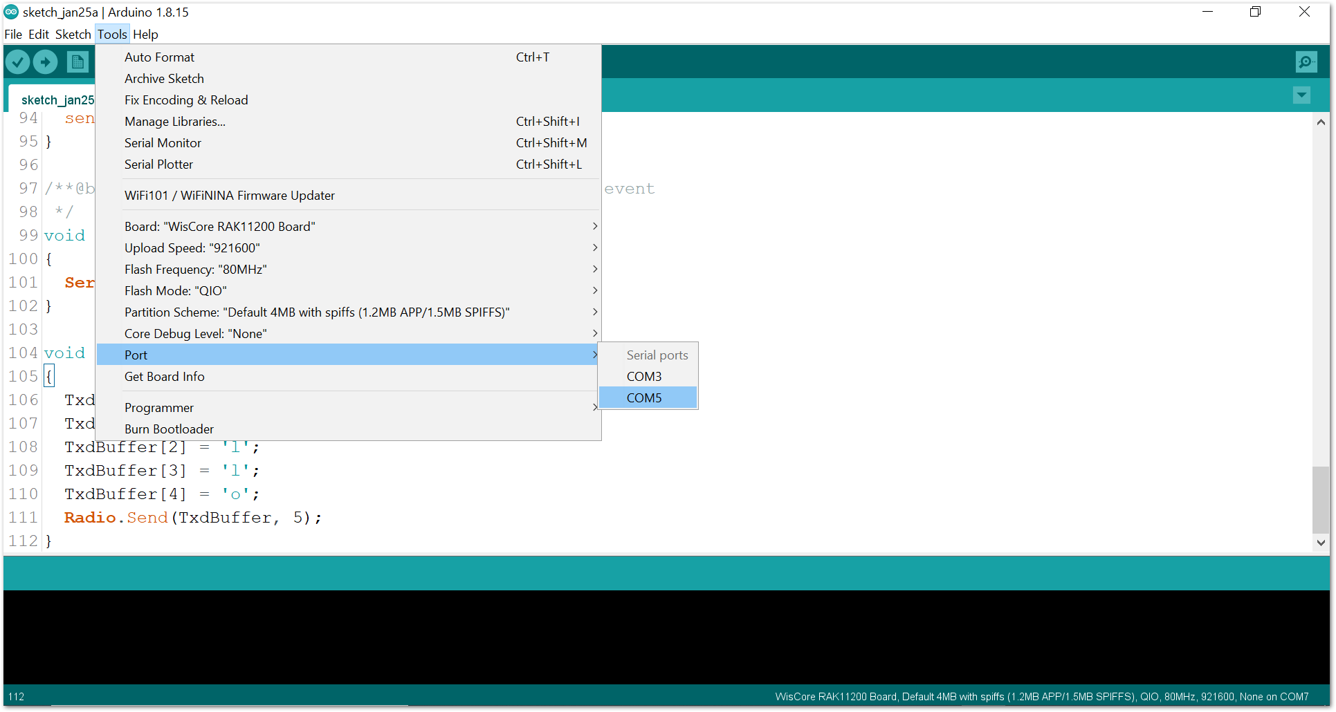 Figure 1: Select the correct Serial Port
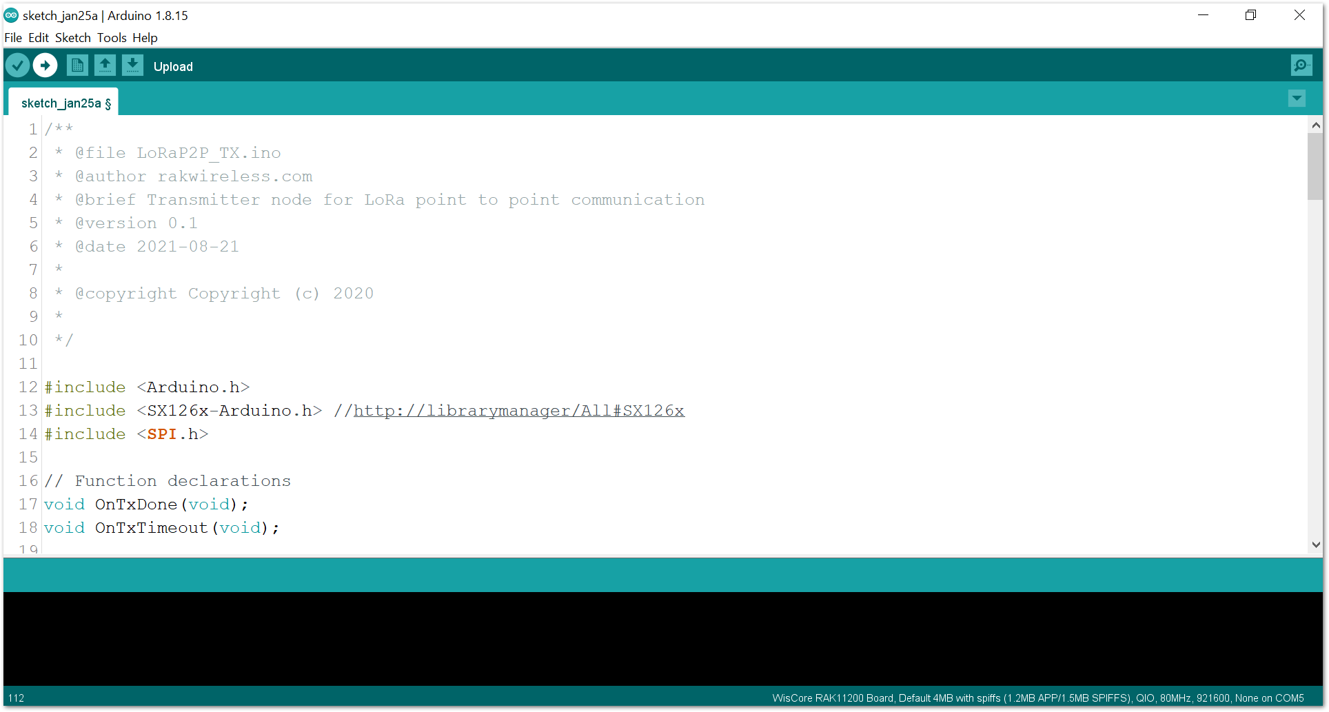 Figure 1: Upload the RAK13302 example code
If you experience any error in compiling the example sketch, make sure that you have the latest version of the SX126x-Arduino library installed. The RAK13302 is supported by library versions V2.0.32 or newer.
- When you have successfully uploaded the example sketch, open the Serial Monitor of the Arduino IDE to see the transmission logs, as shown in Figure 23.
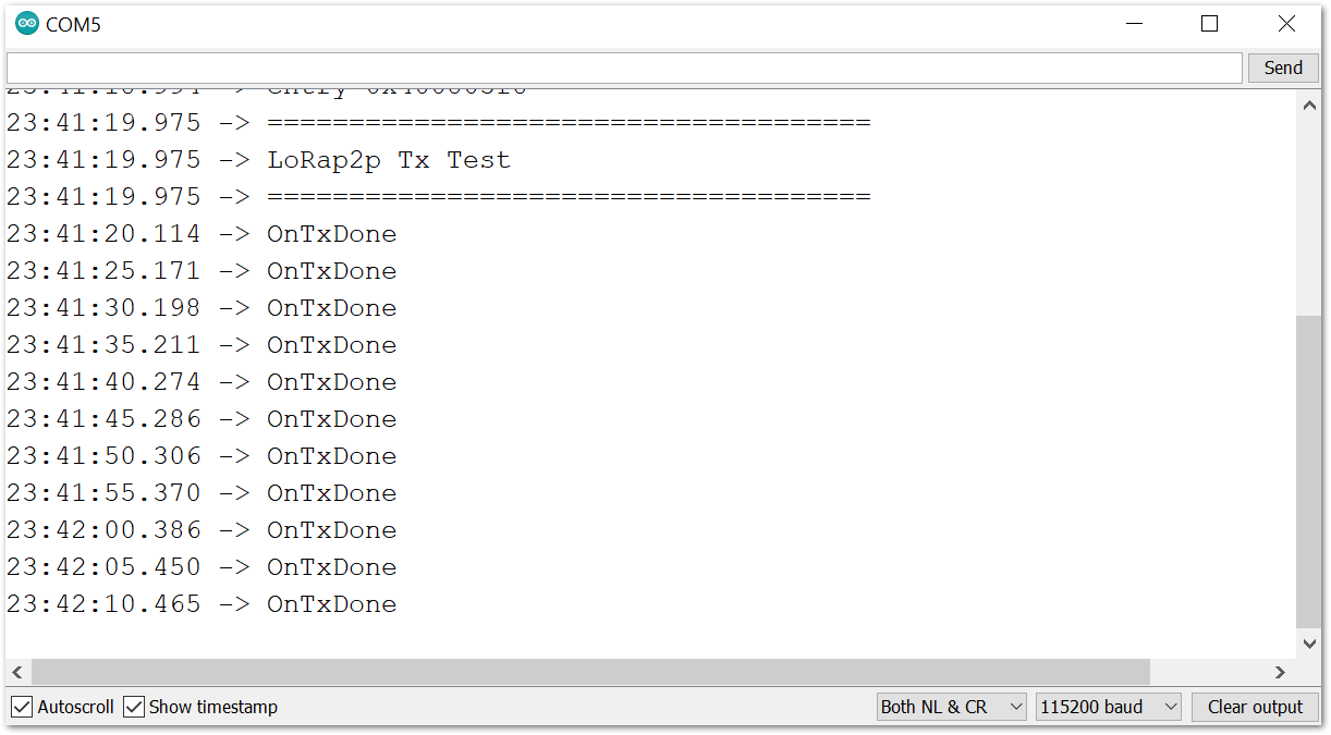 Figure 1: Transmission logs in Serial Monitor
- You can set up a receiver node to see the transmitted messages:
- RAK4631 WisBlock Core as a receiver by with the RAK4631 P2P RX Mode Example
- RAK11310 WisBlock Core as a receiver by using the RAK11310 P2P RX Mode Example
- RAK11200 WisBlock Core and RAK13302 WisBlock LPWAN Module as a receiver.
Set Up RAK13302 as the Transmitter with the RAK11200
If you have already installed the RAKwireless Arduino BSP, the WisBlock Core and example code should now be available on the Arduino IDE.
- If using the RAK11200, you need to select RAK11200 as your WisBlock Core, as shown in Figure 20.
Figure 1: Select RAK11200 as WisBlock Core- Next, copy the following sample code into your Arduino IDE:
Click to view the sample code.
/**
 * @file LoRaP2P_TX.ino
 * @author rakwireless.com
 * @brief Transmitter node for LoRa point to point communication
 * @version 0.1
 * @date 2021-08-21
 *
 * @copyright Copyright (c) 2020
 *
 */

#include <Arduino.h>
#include <SX126x-Arduino.h> //http://librarymanager/All#SX126x
#include <SPI.h>

// Function declarations
void OnTxDone(void);
void OnTxTimeout(void);


// Define LoRa parameters
#define RF_FREQUENCY 868300000  // Hz
#define TX_OUTPUT_POWER 22    // dBm
#define LORA_BANDWIDTH 0    // [0: 125 kHz, 1: 250 kHz, 2: 500 kHz, 3: Reserved]
#define LORA_SPREADING_FACTOR 7 // [SF7..SF12]
#define LORA_CODINGRATE 1   // [1: 4/5, 2: 4/6,  3: 4/7,  4: 4/8]
#define LORA_PREAMBLE_LENGTH 8  // Same for Tx and Rx
#define LORA_SYMBOL_TIMEOUT 0 // Symbols
#define LORA_FIX_LENGTH_PAYLOAD_ON false
#define LORA_IQ_INVERSION_ON false
#define RX_TIMEOUT_VALUE 3000
#define TX_TIMEOUT_VALUE 3000

static RadioEvents_t RadioEvents;
static uint8_t TxdBuffer[64];

void setup()
{
  pinMode(WB_IO2, OUTPUT);
    digitalWrite(WB_IO2, HIGH);
  // Initialize Serial for debug output
  time_t timeout = millis();
  Serial.begin(115200);
  while (!Serial)
  {
    if ((millis() - timeout) < 5000)
    {
            delay(100);
        }
        else
        {
            break;
        }
  }
  Serial.println("=====================================");
  Serial.println("LoRap2p Tx Test");
  Serial.println("=====================================");

  // Initialize the Radio callbacks
  RadioEvents.TxDone = OnTxDone;
  RadioEvents.RxDone = NULL;
  RadioEvents.TxTimeout = OnTxTimeout;
  RadioEvents.RxTimeout = NULL;
  RadioEvents.RxError = NULL;
  RadioEvents.CadDone = NULL;
  // Initialize LoRa chip.
  lora_rak13300_init();
  // Initialize the Radio
  Radio.Init(&RadioEvents);

  // Set Radio channel
  Radio.SetChannel(RF_FREQUENCY);

  // Set Radio TX configuration
  Radio.SetTxConfig(MODEM_LORA, TX_OUTPUT_POWER, 0, LORA_BANDWIDTH,
            LORA_SPREADING_FACTOR, LORA_CODINGRATE,
            LORA_PREAMBLE_LENGTH, LORA_FIX_LENGTH_PAYLOAD_ON,
            true, 0, 0, LORA_IQ_INVERSION_ON, TX_TIMEOUT_VALUE);
  send();
}

void loop()
{
  // Put your application tasks here, like reading of sensors,
  // Controlling actuators and/or other functions.
}

/**@brief Function to be executed on Radio Tx Done event
 */
void OnTxDone(void)
{
  Serial.println("OnTxDone");
  delay(5000);
  send();
}

/**@brief Function to be executed on Radio Tx Timeout event
 */
void OnTxTimeout(void)
{
  Serial.println("OnTxTimeout");
}

void send()
{
  TxdBuffer[0] = 'H';
  TxdBuffer[1] = 'e';
  TxdBuffer[2] = 'l';
  TxdBuffer[3] = 'l';
  TxdBuffer[4] = 'o';
  Radio.Send(TxdBuffer, 5);
}
- You can now select the right serial port and upload the code, as shown in Figure 21 and Figure 22.
Since you are using RAK11200 as WisBlock Core, you need to configure the BOOT0 pin before uploading. Short it to the ground, then press the reset button on the WisBlock Base before releasing the BOOT0 pin. If not done properly, uploading the source code to RAK11200 will fail. Check the full details on the RAK11200 Quick Start Guide.
Figure 1: Select the correct Serial PortFigure 1: Upload the RAK13302 example codeIf you experience any error in compiling the example sketch, check the updated code for the RAK13302 WisBlock LPWAN Wireless Module that can be found on the RAK13302 WisBlock Example Code Repository.
- When you have successfully uploaded the example sketch, open the Serial Monitor of the Arduino IDE to see the transmission logs, as shown in Figure 23.
Figure 1: Transmission logs in Serial Monitor- You can set up a receiver node to see the transmitted messages:
- RAK4631 WisBlock Core as a receiver by with the RAK4631 P2P RX Mode Example
- RAK11310 WisBlock Core as a receiver by using the RAK11310 P2P RX Mode Example
- RAK11200 WisBlock Core and RAK13302 WisBlock LPWAN Module as a receiver.