RAK14004 and RAK14011 WisBlock Keypad Quick Start Guide
Prerequisite
- Assemble the RAK14004 with a WisBlock Base and WisBlock Core by following the RAK14004 Installation Guide.
- Download and install the Arduino IDE, then add the RAKwireless Core boards by installing the RAKwireless Arduino BSP.
- Your choice of RAK14011 WisBlock Keypad 4x4.
- USB Cable
- Li-Ion/LiPo battery (optional)
- Solar charger (optional)
Software Configuration and Example
The RAK14004 module can be used with the RAK14009, RAK14010, or RAK14011 WisBlock Keypad modules. This guide uses the RAK14009 as an example to demonstrate the configuration process.
NOTE
- This guide uses the RAK4631 WisBlock Core to demonstrate the configuration process. You can also use the RAK11200 or RAK11310 as the WisBlock Core.
- When using the RAK11200, configure the BOOT0 pin correctly before uploading the source code. Otherwise, the upload may fail. For detailed instructions, refer to the RAK11200 Quick Start Guide.
- First, you need to select your WisBlock Core
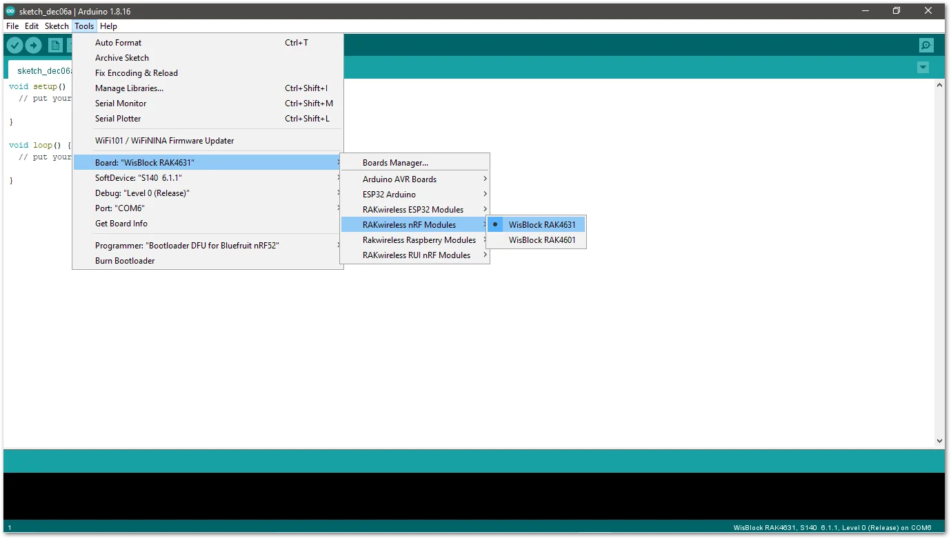 Figure 1: Selecting RAK4631 as WisBlock Core
- Copy the following example code into your Arduino IDE:
Click to view the code
/**
   @file RAK14011_Keypad.ino
   @author rakwireless.com
   @brief 4*4 Keypad
   @version 0.1
   @date 2021-10-19
   @copyright Copyright (c) 2021
**/
#include <Wire.h>
#include "Arduino.h"
#define SLAVE_I2C_ADDRESS_DEFAULT            0x5F

//Sensor Register Addresses
#define SENSOR_GET_KEYPAD        0x01 // (r)   2 bytes
#define SENSOR_GET_I2C_ADDRESS   0x02  // (r)   1 bytes
#define SENSOR_SET_I2C_ADDRESS   0x03  // (w)   1 bytes
#define SENSOR_GET_VERSION       0x04 // (r)   1 bytes

#define KEYPAD_VERSION           0x02
#define KEYPAD_SIZE_X            0x04
#define KEYPAD_SIZE_Y            0x04
uint8_t InterruptFlag = 0;

void setup()
{
  //enable sensor
  pinMode(WB_IO2, OUTPUT);
  digitalWrite(WB_IO2, LOW);
  delay(1000);
  digitalWrite(WB_IO2, HIGH);
  delay(300);

  pinMode(WB_IO6, INPUT_PULLUP); //Interrupt
  pinMode(LED_BLUE, OUTPUT);
  digitalWrite(LED_BLUE, HIGH);
  attachInterrupt(WB_IO6, INTCallBack, RISING); // Enable interrupts.
  Wire.begin();
  Serial.begin(115200); // Initialize Serial for debug output.
  delay(3000);
  Serial.println("*******Keypad**********");
  uint8_t data = 0;
  read_from_Atmega328p(SENSOR_GET_VERSION, &data, 1);
  if (data != KEYPAD_VERSION)
  {
    Serial.println("sensor not find");
    while (1);
  }
  Serial.print("Sensor Firmware version: ");
  Serial.println(data);
  Serial.println();
  Serial.println("4*4 Keypad");
  delay(500);
}

void INTCallBack(void)
{
  InterruptFlag = 1;
}


/*brief: IIC Read data*/
uint8_t readflag = 0;
void read_from_Atmega328p(uint8_t reg, uint8_t *data, uint8_t length)
{
  Wire.beginTransmission(SLAVE_I2C_ADDRESS_DEFAULT);
  Wire.write(reg);
  Wire.endTransmission();    // stop transmitting
  delay(20);
  Wire.requestFrom(SLAVE_I2C_ADDRESS_DEFAULT, length);
  int i = 0;
  while ( Wire.available() ) // slave may send less than requested
  {
    data[i++] = Wire.read(); // receive a byte as a proper uint8_t
    readflag = 1;
  }
}

/*brief: IIC write data*/
void write_to_Atmega328p(uint8_t reg, uint8_t data)
{
  Wire.beginTransmission(SLAVE_I2C_ADDRESS_DEFAULT);
  Wire.write(reg);
  Wire.write(data);
  Wire.endTransmission();    // stop transmitting
}

void KeyPad_Print(void)
{
  if (InterruptFlag == 1)
  {
    uint8_t rDataBuf[8] = {0};
    uint8_t PrintDataBuf[2] = {0};
    uint8_t rDataFlag[2] = {0};
    read_from_Atmega328p(SENSOR_GET_KEYPAD, rDataBuf, KEYPAD_SIZE_X);
    if (readflag == 1)
    {
      Serial.println("-----------------------");
      for (uint8_t aCount = 0; aCount < KEYPAD_SIZE_X; aCount++)
      {
        for (uint8_t bCount = 0; bCount < KEYPAD_SIZE_Y; bCount++ )
        {
          uint8_t cmp = (rDataBuf[aCount] >> bCount) & 0x01;
          if (cmp == 0x01)
          {
            rDataFlag[0]++;
            if (rDataFlag[0] <= 2)
            {
              rDataFlag[1]++;
              PrintDataBuf[rDataFlag[0] - 1] = aCount * KEYPAD_SIZE_Y + bCount + 1;
            }
            else
            {
              rDataFlag[1] = 0;
              Serial.println("Error please do not press more than two buttons at the same time ");
              return;
            }
          }
        }
      }
      readflag = 0;
    }
    for (uint8_t pCount = 0; pCount < rDataFlag[1]; pCount++)
    {
      Serial.printf("K%d pressed\r\n", PrintDataBuf[pCount]);
    }
    Serial.println("-----------------------");
    Serial.println();
    InterruptFlag = 0;
  }
}

void loop() {
  KeyPad_Print();
  delay(100);
}
- Now, select the right Serial Port and upload the code.
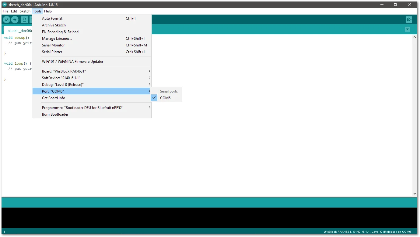 Figure 1: Selecting the RAK4631 Serial Port
- When you successfully uploaded the sample code, open the Serial Monitor of the Arduino IDE to check the module's reading logs. If you see the logs, then your RAK14004 module is properly communicating to the WisBlock Core using the I²C interface.
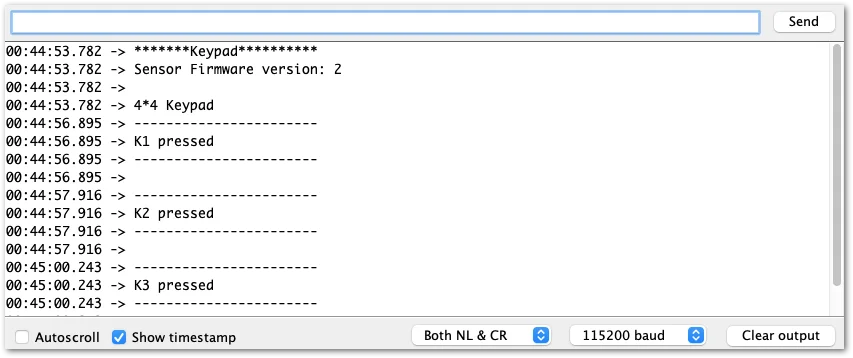 Figure 1: RAK14004 and RAK14011 on RAK4631 data logs


