RAK3272-SiP Quick Start Guide
Prerequisites
Before going through the step in the installation guide of the RAK3272-SiP Breakout Board, make sure to prepare the necessary items listed below:
Hardware
- RAK3272-SiP Breakout Board
- RAKDAP1 Flash and Debug Tool (or any USB-Serial Adapter)
- ST-LINK in-circuit debugger/programmer (optional)
- Windows/Mac OS/Linux Computer with USB port
Software
- Download and install the Arduino IDE.
If you are using Windows 10:
Do NOT install the Arduino IDE from the Microsoft App Store. Instead, install the original Arduino IDE from the Arduino official website. The Arduino app from the Microsoft App Store has problems using third-party Board Support Packages.
- Add RAK3272-SiP as a supported board in Arduino IDE by updating Board Manager URLs in Preferences settings of Arduino IDE with this JSON URL
https://raw.githubusercontent.com/RAKWireless/RAKwireless-Arduino-BSP-Index/main/package_rakwireless_com_rui_index.json. After that, add RAKwireless RUI STM32 Boards via Arduino board manager. - RAK Serial Port Tool
- RAK DFU Tool
- STM32CubeProgrammer (optional)
List of Acronyms
| Acronym | Definition |
|---|---|
| DFU | Device Firmware Upgrade |
| JTAG | Joint Test Action Group |
| LoRa | Long Range |
| OTAA | Over-The-Air-Activation (OTAA) |
| ABP | Activation-By-Personalization (ABP) |
| TTN | The Things Network |
| DEVEUI | Device EUI (Extended Unique Identification) |
| APPEUI | Application EUI (Extended Unique Identification) |
| APPKEY | Application Key |
| DEVADDR | Device Address |
| NWKSKEY | Network Session Key |
| APPSKEY | Application Session Key |
| P2P | Point-to-Point |
Product Configuration
RAK3272-SiP Breakout Board as a Stand-Alone Device Using RUI3
Hardware Setup
The RAK3272-SiP requires a few hardware connections to function properly. At a minimum, ensure the following components are correctly set up:
- Power section configuration
- Reset button
- Antenna
- USB connection
-
Firmware updates for the RAK3272-SIP are performed via the UART2 pins. If you plan to connect the module to an external device interfacing with UART2, take extra precautions in your board design to ensure firmware updates can still be performed.
-
Your board design should include a mechanism to disconnect the external device from the RAK3272-SIP breakout board's UART2 pins before connecting the module to a PC (via a USB-UART converter) for the firmware update process.
-
An alternative option to update firmware aside from UART2 is to use SWD pins (SWCLK and SWDIO). This method will require the use of external tools like ST-LINK or RAKDAP1.
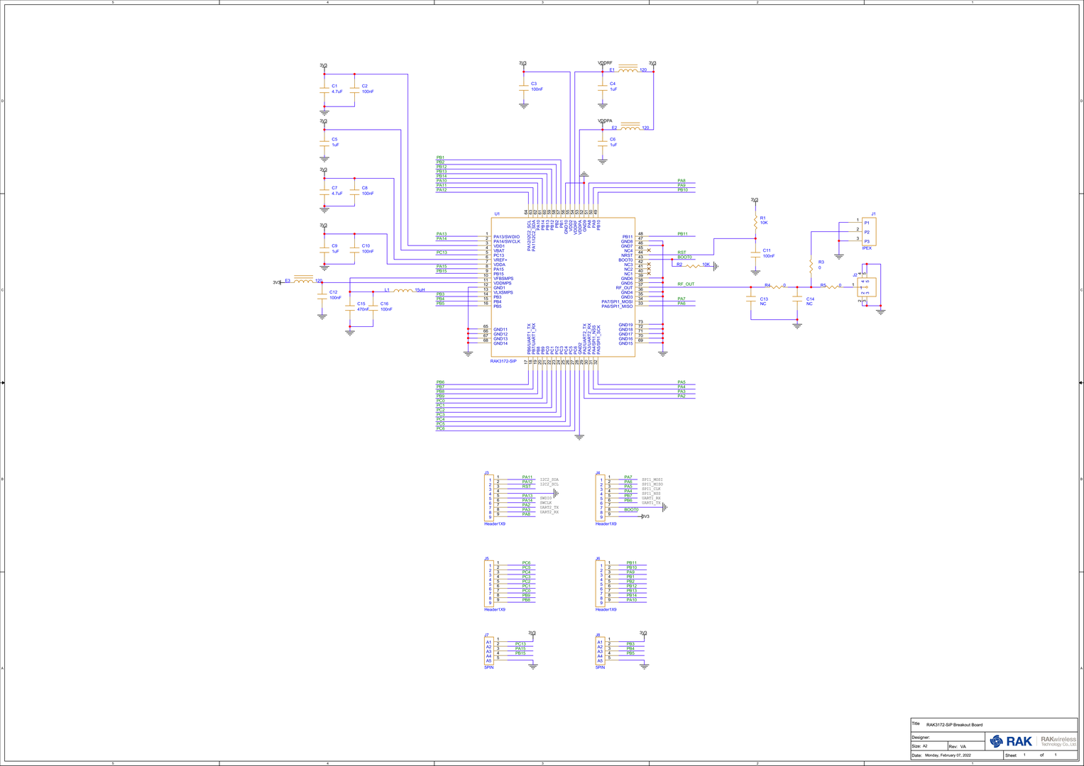 Figure 1: RAK3272-SiP Schematic
Ensure the antenna is properly connected to ensure a strong LoRa signal. Additionally, note that powering the module without an antenna connected to the RP-SMA connector can damage the RF section of the chip.
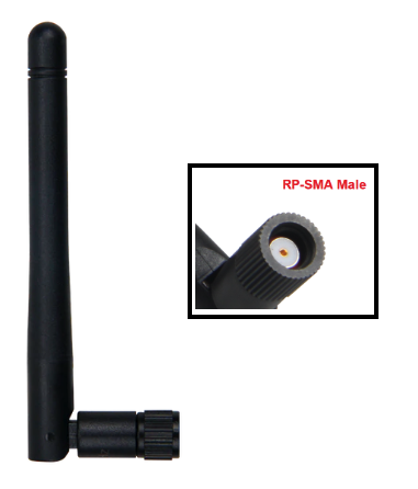 Figure 1: LoRa Antenna
- The RAK3272-SiP features an RP-SMA connector that is compatible with the included LoRa antenna, as illustrated in Figure 3.
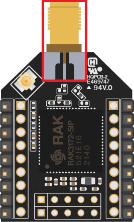 Figure 1: RP-SMA Connector of RAK3272-SiP for LoRa Antenna
Detailed information about the RAK3272-SiP LoRa antenna can be found on the antenna datasheet.
When using the LoRa transceiver, make sure that an antenna is always connected. Using this transceiver without an antenna can damage the module.
Software Setup
The default firmware of the RAK3272-SIP is based on RUI3, enabling the development of custom firmware to connect sensors and other peripherals. To create custom firmware using the Arduino IDE:
- Add RAKwireless RUI STM32 Boards in the Arduino Board Manager, as outlined in this guide.
- Use RUI3 APIs to develop your application.
- Upload the custom firmware via UART.
The AT commands for the RAK3272-SIP remain accessible even when custom firmware is compiled and uploaded using RUI3. These commands can be sent via the UART2 connection.
RAK3272-SiP RUI3 Board Support Package in Arduino IDE
If you don't have an Arduino IDE yet, download it on the Arduino official website and follow the installation procedure in the miscellaneous section of this document.
For Windows 10 and up users: If you installed the Arduino IDE from the Microsoft App Store, uninstall it and reinstall the IDE from the Arduino official website. The version from the Microsoft App Store has issues with third-party Board Support Packages.
After successfully installing the Arduino IDE, configure it to add the RAK3272-SIP to its board selection by following these steps:
- Open Arduino IDE and go to File > Preferences.
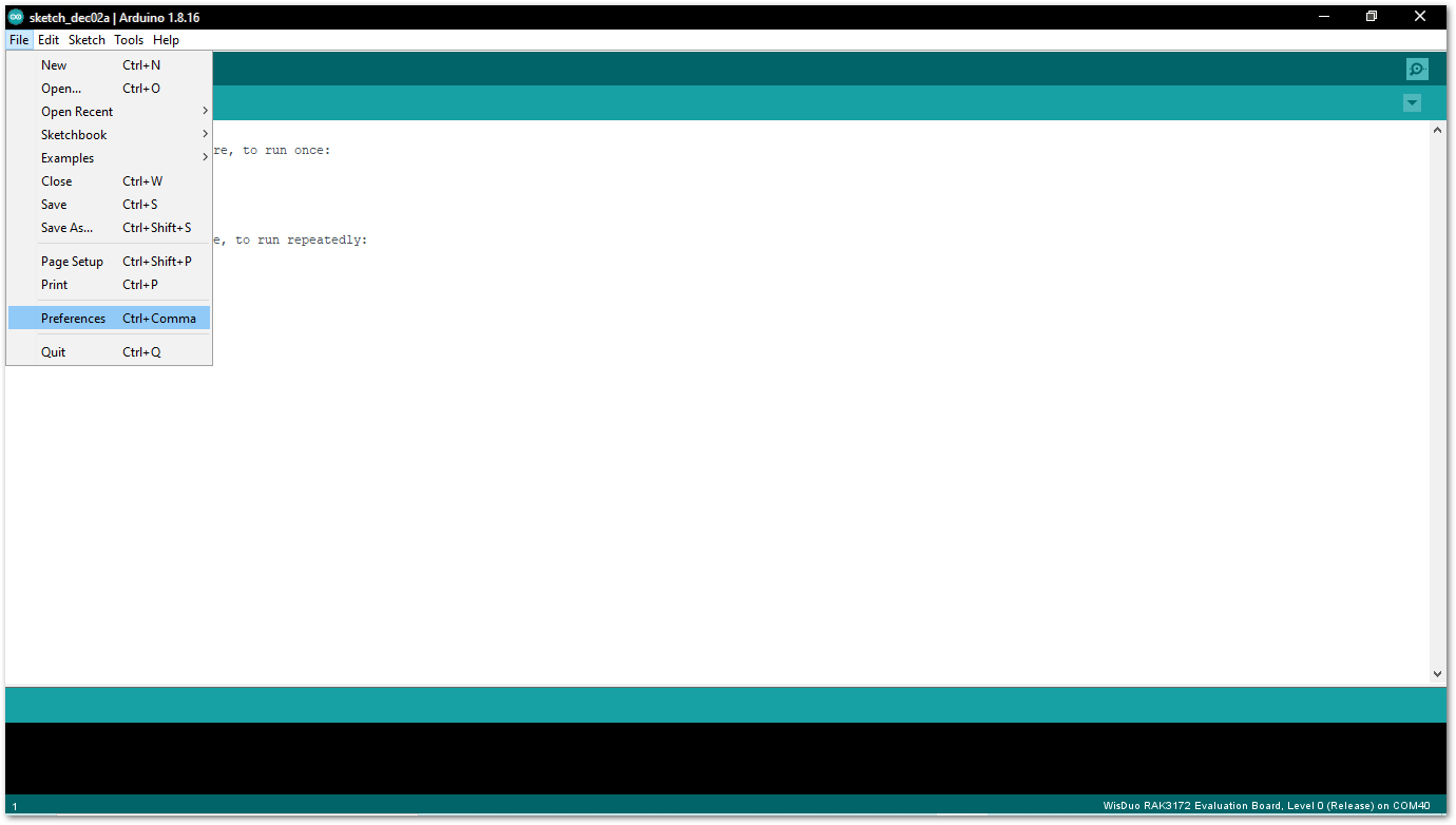 Figure 1: Arduino preferences
- To add the RAK3272-SiP to your Arduino Boards list, edit the Additional Board Manager URLs and click the icon, as shown in Figure 5.
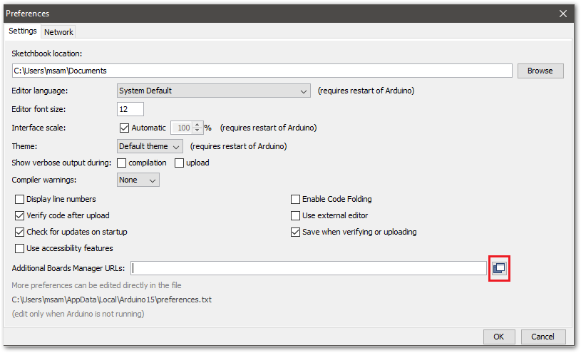 Figure 1: Modify Additional Board Manager URLs
- Copy the URL
https://raw.githubusercontent.com/RAKWireless/RAKwireless-Arduino-BSP-Index/main/package_rakwireless_com_rui_index.jsonand paste it on the field. If there are other URLs already there, just add them on the next line. After adding the URL, click OK.
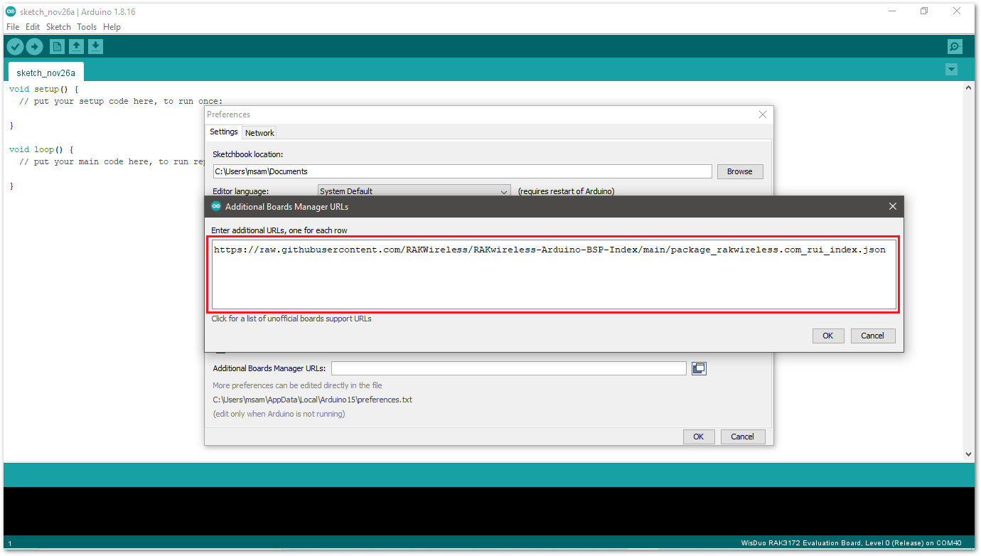 Figure 1: Add additional board manager URLs
- Restart the Arduino IDE.
- Open the Boards Manager from the Tools Menu.
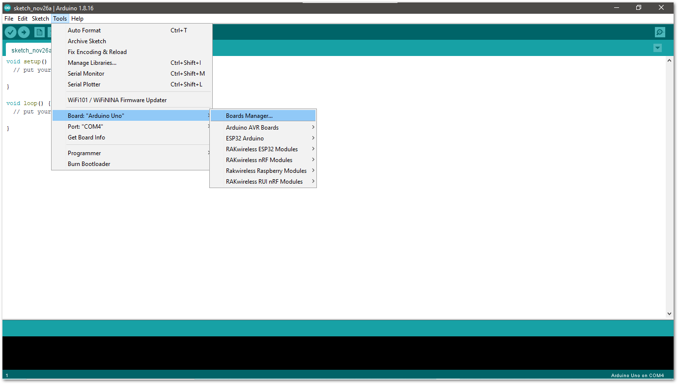 Figure 1: Open Arduino boards manager
- Write
RAKin the search bar, as shown in Figure 8. This will show the available RAKwireless module boards that you can add to your Arduino Board list. Select and install the latest version of the RAKwireless RUI STM32 Boards.
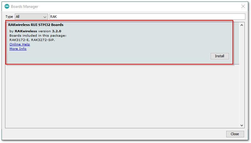 Figure 1: Install RAKwireless RUI STM32 boards
- Once the BSP is installed, select Tools > Boards Manager > RAKWireless RUI STM32 Modules > WisDuo RAK3272-SiP Board. The RAK3272-SiP breakout board uses the RAK3172-SiP WisDuo module.
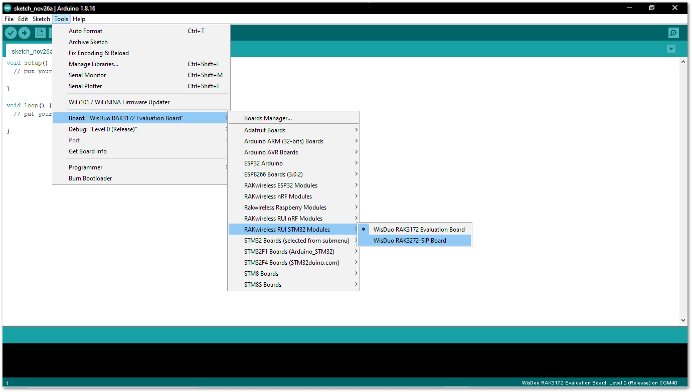 Figure 1: Select RAK3272-SiP Board
Compile an Example with Arduino Serial
- After adding the RAK3272-SiP to the Arduino IDE, test your setup by running a simple program. Ensure a USB connection is included in the schematic of the RAK3272-SiP breakout board, as illustrated in Figure 10.
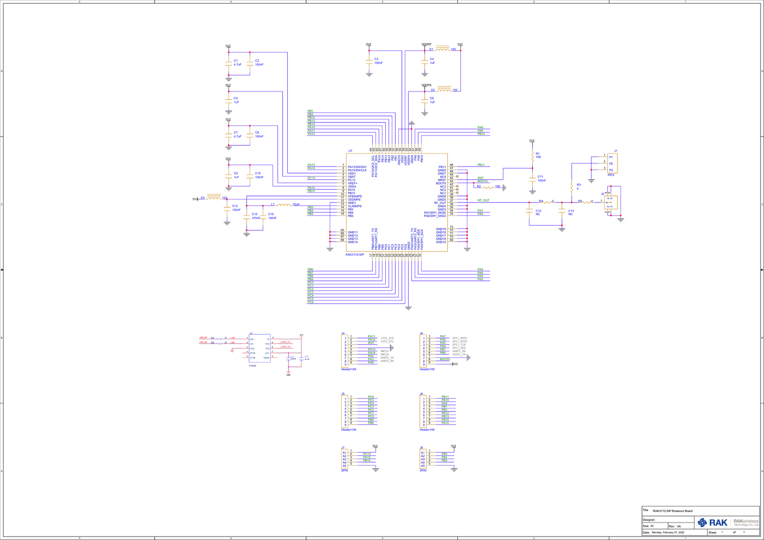 Figure 1: RAK3272-SiP with USB to Serial Schematic
- Connect the RAK3272-SiP via UART and check RAK3272-SiP COM Port using Windows Device Manager. Double-click the reset button if the module is not detected.
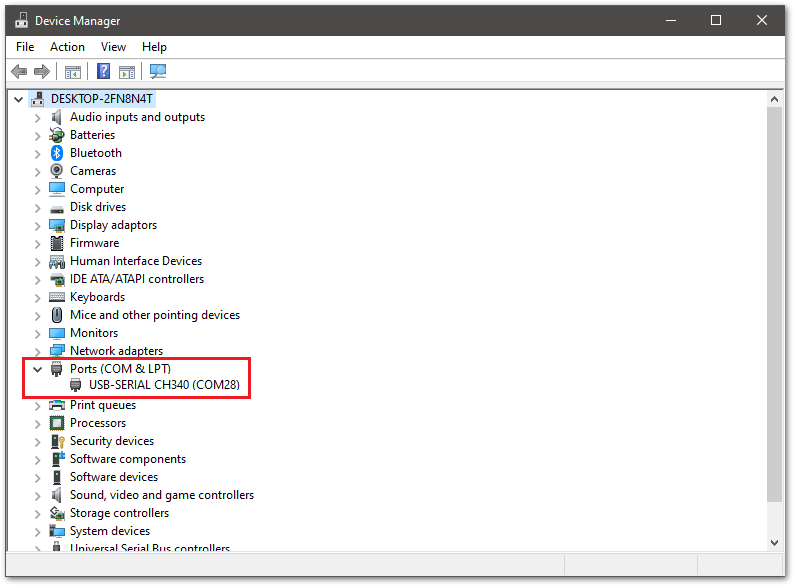 Figure 1: Device manager ports (COM & LPT)
- Choose RAK3272-SiP on board selection select via Tools > Boards Manager > RAKWireless RUI STM32 Modules > WisDuo RAK3272-SiP Board.
Figure 1: Select RAK3272-SiP Breakout Board- Open the Tools menu and select the COM port. In this case, select COM28, as it is currently in use.
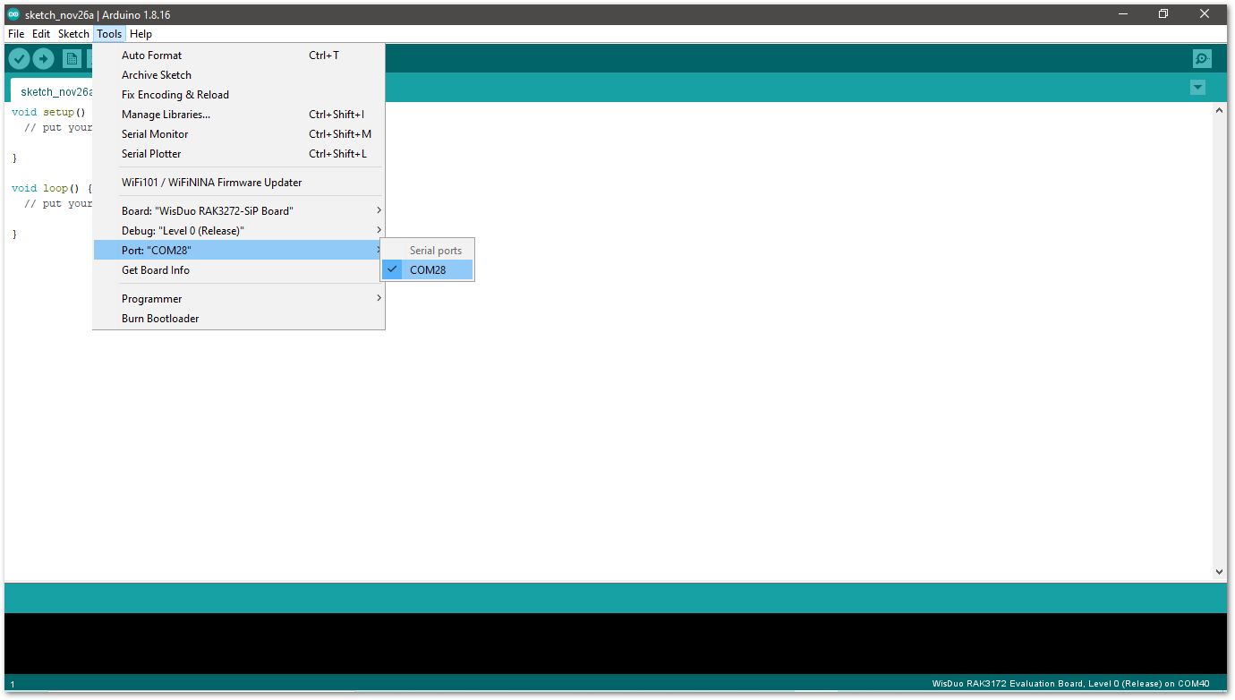 Figure 1: Select COM port
- Click on the Serial Monitor icon to connect to the COM port.
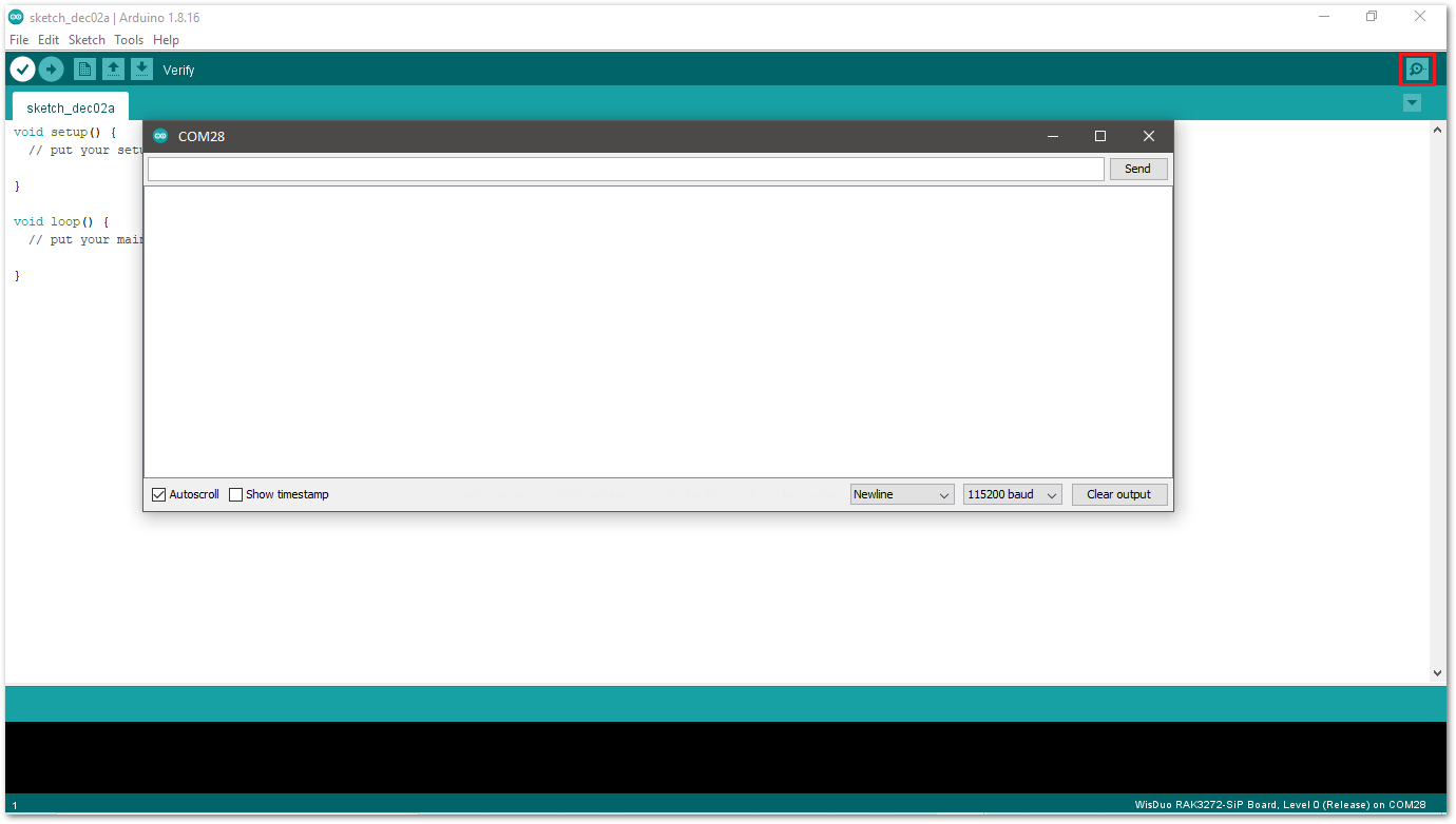 Figure 1: Open Arduino serial monitor
- To test the connection, send AT commands to the RAK3272-SIP. For instance, to check the RUI version, type
AT+VER=?in the text area and click the Send button.
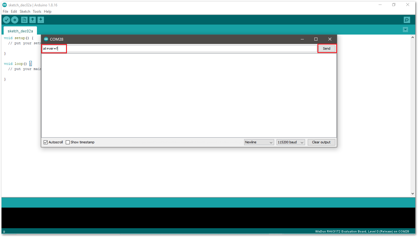 Figure 1: Send AT command
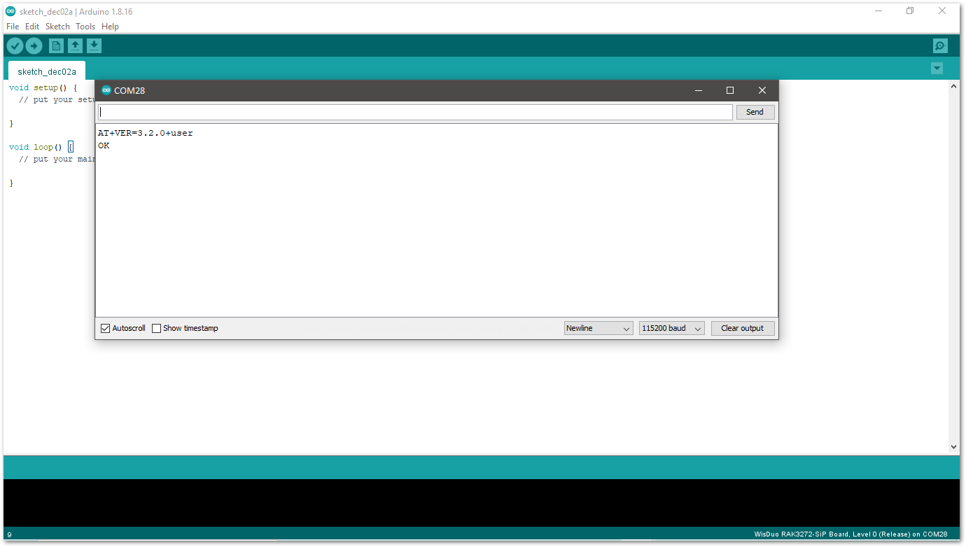 Figure 1: Arduino serial monitor COM28
- Open the Arduino_Serial example code.
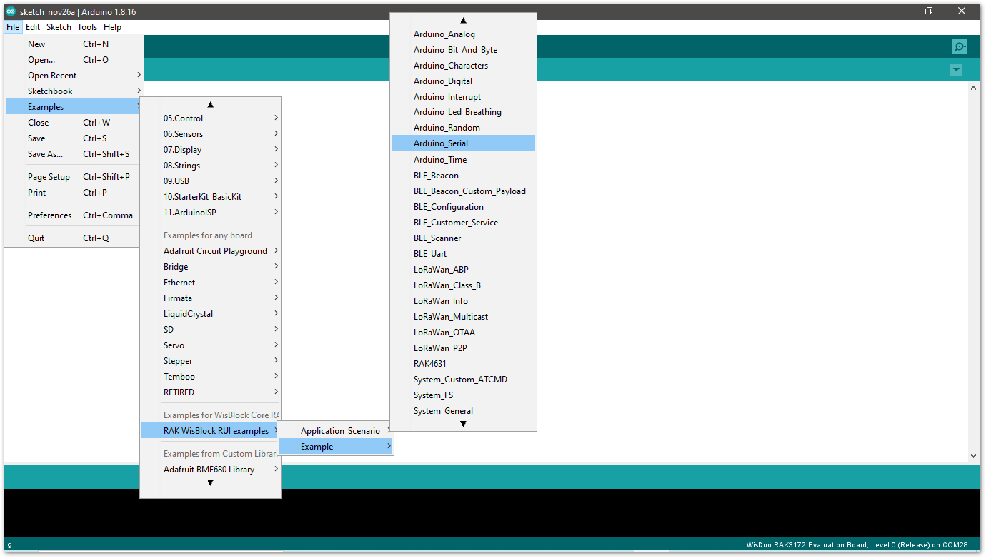 Figure 1: Arduino Serial example
- Click on the Verify icon to check if you have successfully compiled the example code.
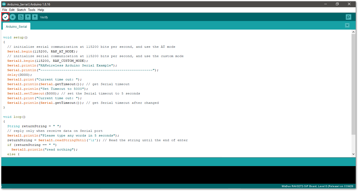 Figure 1: Verify the example code
- Click the Upload icon to send the compiled firmware to your RAK3272-SiP.
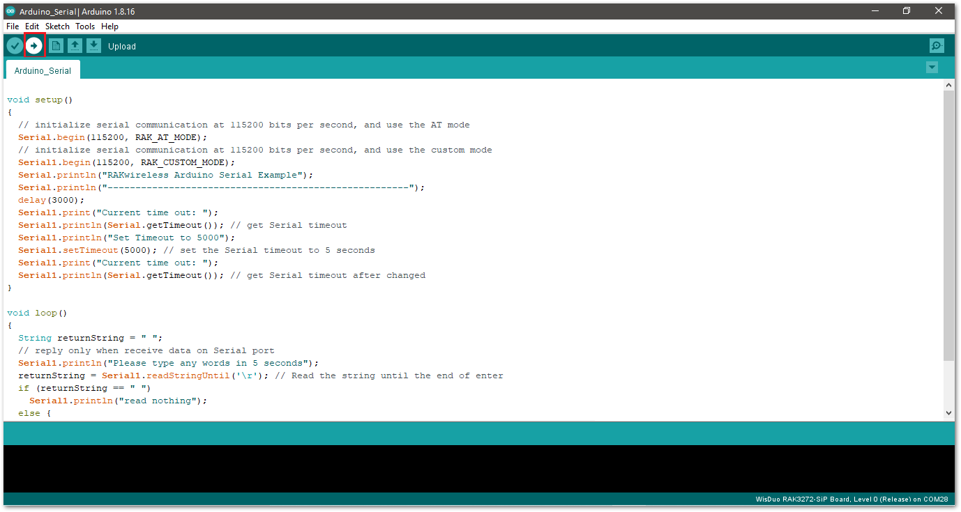 Figure 1: Upload the example code
- If the upload is successful, you will see the Device programmed message.
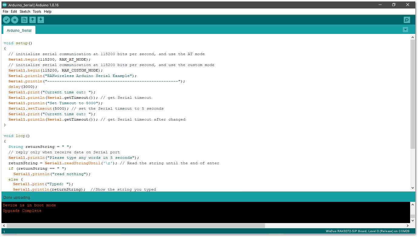 Figure 1: Device programmed successfully
Once the device programming is complete, the Arduino_Serial example will be operational, indicating successful execution.
RAK3272-SiP Breakout Board I/O Pins and Peripherals
This section discusses how to use and access RAK3272-SiP pins using RUI3 API. It shows basic code using digital I/O, analog input, UART, and I2C.
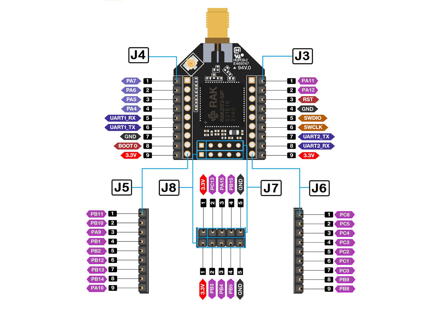 Figure 1: Available Peripherals and Digital I/O pins in RAK3272-SiP Breakout Board
How to Use Digital I/O
You can use any of the pins below as Digital Pin.
| Pin Name | Alternative Pin Usage |
|---|---|
| PA4 | SPI1_NSS |
| PA5 | SPI1_CLK |
| PA6 | SPI1_MISO |
| PA7 | SPI1_MOSI |
| PA8 | |
| PA9 | |
| PA10 | |
| PA11 | I2C_SCL |
| PA12 | I2C_SDA |
| PA15 | |
| PB1 | |
| PB2 | |
| PB3 | ADC0 |
| PB4 | ADC1 |
| PB5 | |
| PB6 | UART1_TX |
| PB7 | UART1_RX |
| PB8 | |
| PB9 | |
| PB10 | |
| PB11 | |
| PB12 | |
| PB13 | |
| PB14 | |
| PB15 | |
| PC0 | |
| PC1 | |
| PC2 | |
| PC3 | |
| PC4 | |
| PC5 | |
| PC6 | |
| PC13 |
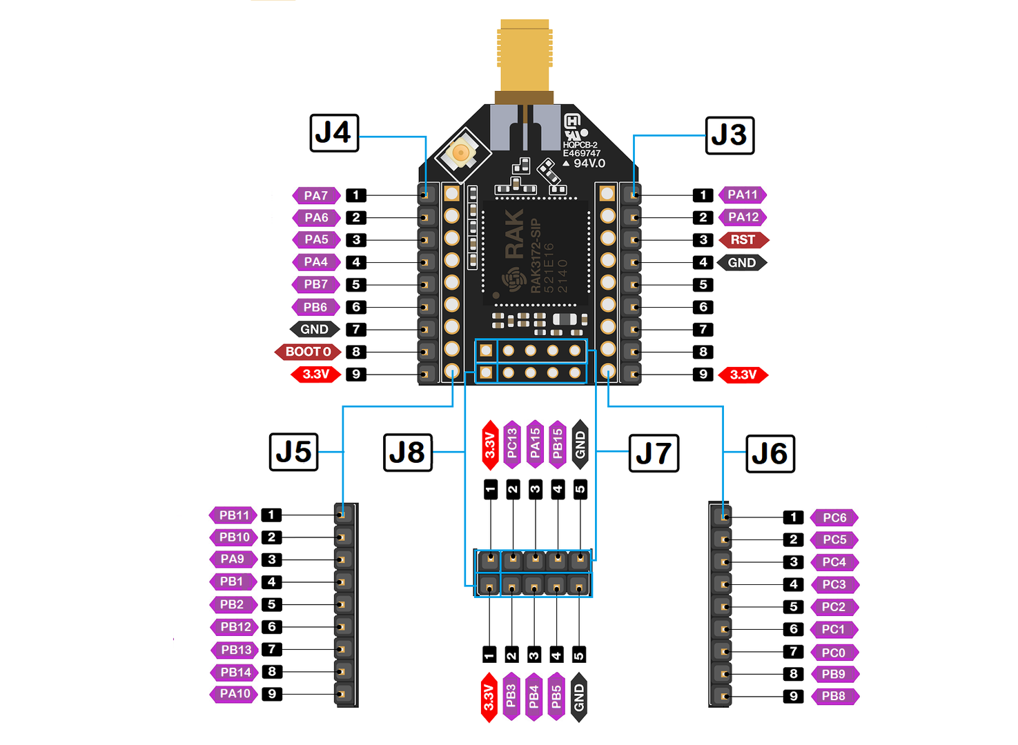 Figure 1: Available Digital I/O pins in RAK3172-SiP Breakout Board
The pins listed below must not be used.
| Pin name | Pin Location | Pin Usage |
|---|---|---|
| PA2 | J3 pin 7 | UART2_TX |
| PA3 | J3 pin 8 | UART2_RX |
| PA13 | J3 pin 5 | SWDIO |
| PA14 | J3 pin 6 | SWCLK |
The GPIO Pin Name is the one to be used on the digitalRead and digitalWrite and NOT the pin numbers.
- Use Arduino digitalRead to read the value from a specified Digital I/O pin, either HIGH or LOW.
- Use Arduino digitalWrite to write a HIGH or a LOW value to a Digital I/O pin.
Example code
void setup()
{
  pinMode(PA9, OUTPUT); //Change the PA9 to any digital pin you want. Also, you can set this to INPUT or OUTPUT
}

void loop()
{
  digitalWrite(PA9,HIGH); //Change the PA9 to any digital pin you want. Also, you can set this to HIGH or LOW state.
  delay(1000); // delay for 1 second
  digitalWrite(PA9,LOW); //Change the PA9 to any digital pin you want. Also, you can set this to HIGH or LOW state.
  delay(1000); // delay for 1 second
}
How to Use Analog Input
You can use any of the pins below as Analog Input.
| Pin Location | Analog Port | Pin Name |
|---|---|---|
| J8 pin 2 | ADC0 | PB3 |
| J8 pin 3 | ADC1 | PB4 |
- Use Arduino analogRead to read the value from the specified Analog Input pin.
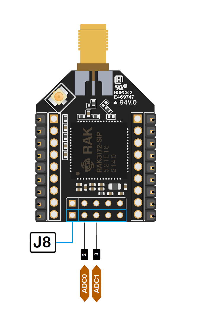 Figure 1: Available Analog pins in RAK3272-SiP Breakout Board
Example code
#define analogPin PB3

int val = 0;  // variable to store the value read

void setup()
{
  Serial.begin(115200);
}

void loop()
{
  val = analogRead(analogPin);  // read the input pin
  Serial.println(val);          // debug value
  delay(100);
}
How to Use Serial Interfaces
UART
There are two UART peripherals available on the RAK3172 module. There are also different Serial Operating Modes possible in RUI3, namely Binary Mode, AT Mode, and Custom Mode.
UART Pin map table
| Pin Location | Serial Port | Serial Instance Assignment | Default Mode |
|---|---|---|---|
| J4 pin 5 | UART1_RX | Serial1 | Custom Mode |
| J4 pin 6 | UART1_TX | Serial1 | Custom Mode |
| J3 pin 8 | UART2_RX | Serial | AT Command |
| J3 pin 7 | UART2_TX | Serial | AT Command |
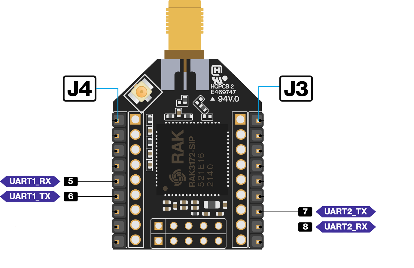 Figure 1: Available UART pins in RAK3272-SiP Breakout Board
Example Code
void setup()
{
  Serial1.begin(115200); // use Serial1 for UART1 and Serial for UART2
                         // you can designate separate baudrate for each.
  Serial.begin(115200);
}

void loop()
{
  Serial1.println("RAK3272-SiP UART1 TEST!");
  Serial.println("RAK3272-SiP UART2 TEST!");
  delay(1000); // delay for 1 second
}
I2C
There is one I2C peripheral available on RAK3272-SiP.
| Pin Location | I2C Port | Pin Name |
|---|---|---|
| J3 pin 1 | I2C_SCL | PA11 |
| J3 pin 2 | I2C_SDA | PA12 |
- Use Arduino Wire library to communicate with I2C devices.
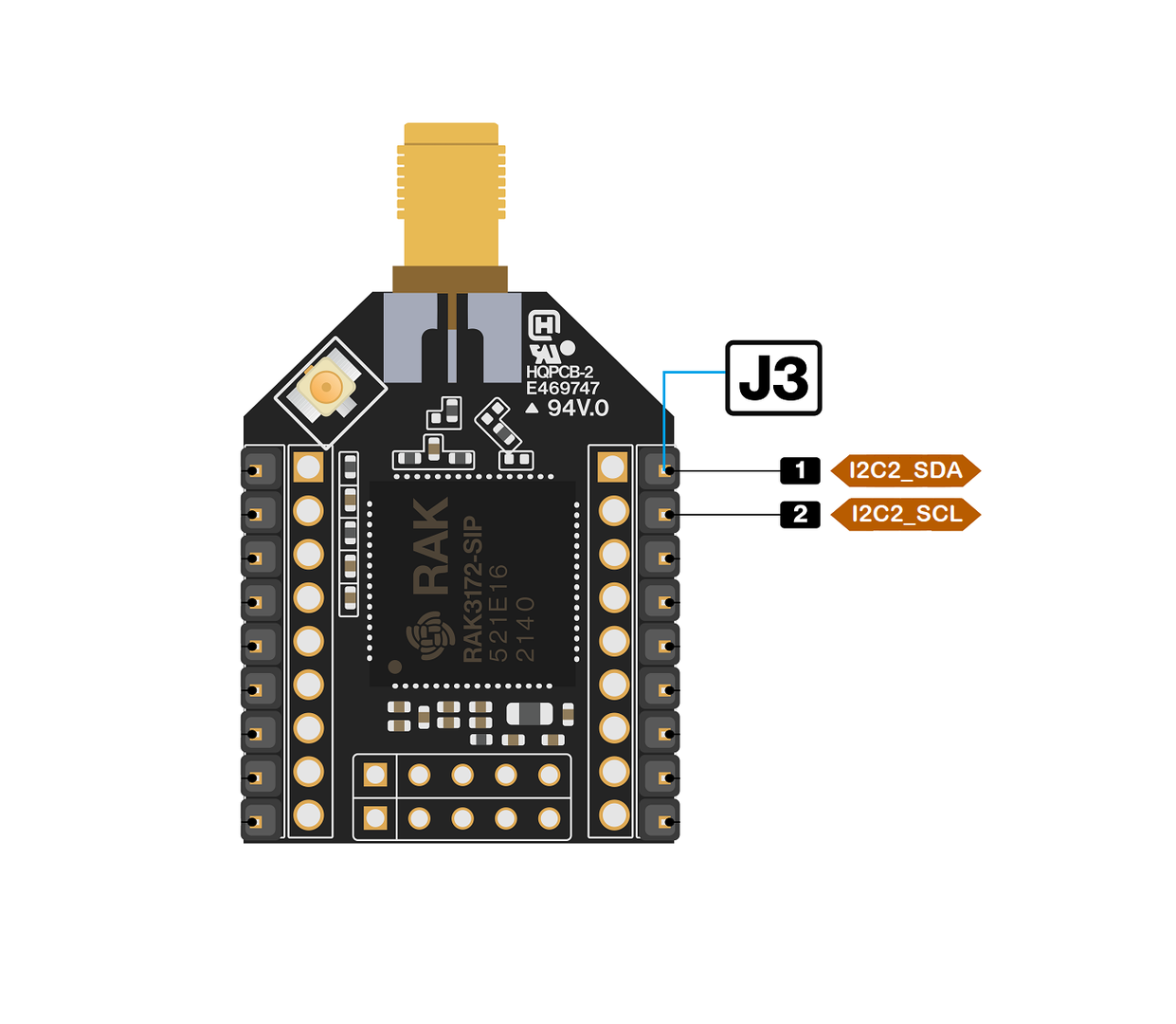 Figure 1: Available I2C pins in RAK3272-SiP Breakout Board
Example Code
Make sure you have an I2C device connected to specified I2C pins to run the I2C scanner code below:
#include <Wire.h>

void setup()
{
  Wire.begin();

  Serial.begin(115200);
  while (!Serial);
  Serial.println("\nI2C Scanner");
}


void loop()
{
  byte error, address;
  int nDevices;

  Serial.println("Scanning...");

  nDevices = 0;
  for(address = 1; address < 127; address++ )
  {
    // The i2c_scanner uses the return value of
    // the Write.endTransmission to see if
    // a device did acknowledge to the address.
    Wire.beginTransmission(address);
    error = Wire.endTransmission();

    if (error == 0)
    {
      Serial.print("I2C device found at address 0x");
      if (address<16)
        Serial.print("0");
      Serial.print(address,HEX);
      Serial.println("  !");

      nDevices++;
    }
    else if (error==4)
    {
      Serial.print("Unknown error at address 0x");
      if (address<16)
        Serial.print("0");
      Serial.println(address,HEX);
    }
  }
  if (nDevices == 0)
    Serial.println("No I2C devices found\n");
  else
    Serial.println("done\n");

  delay(5000);           // wait 5 seconds for next scan
}
The Arduino Serial Monitor shows the I2C device found.
17:29:15.690 -> Scanning...
17:29:15.738 -> I2C device found at address 0x28  !
17:29:15.831 -> done
17:29:15.831 ->
17:29:20.686 -> Scanning...
17:29:20.733 -> I2C device found at address 0x28  !
17:29:20.814 -> done
17:29:20.814 ->
SPI
If your RUI3 project uses SPI, then J4 pins 1 to 4 are reserved for the RUI3 SPI interface.
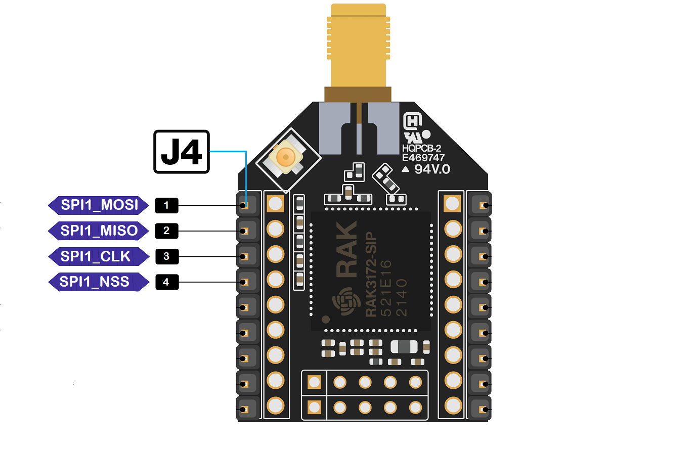 Figure 1: Available SPI pins in RAK3272-SiP Breakout Board
More examples for the RAK3172-SiP can be found in the RUI3-Best-Practices on Github.
RAK3272-SiP Breakout Board as a LoRa/LoRaWAN Modem via AT Command
AT Command via UART2
The RAK3272-SiP Breakout Board is configured using AT commands through the UART2 interface. To connect the RAK3272-SiP to your computer's USB port, you'll need a USB to UART TTL adapter and a serial terminal tool. The RAK Serial Port Tool allows you to send AT commands and view console output responses easily. While the RAK Serial Port Tool uses RUI V2 AT commands by default, you can modify and save it to use RUI3 AT commands.
-
Firmware updates and AT command functionality are performed through UART2 pins. When connecting the module to an external host MCU for AT commands via UART2, ensure your board design allows for future firmware updates.
-
Your design should include a method to disconnect the host MCU UART from the RAK3272-SiP UART2 before connecting the module to the PC (using a USB-UART converter) for firmware updates.
-
Alternatively, you can update firmware using SWD pins (SWCLK & SWDIO). This method requires external tools such as ST-LINK or RAKDAP1.
Connect to the RAK3272-SiP Breakout Board
- Connect the RAK3272-SiP Breakout Board to the RAKDAP1 or any USB-Serial adapter with 3.3 V voltage supply, as shown in Figure 27.
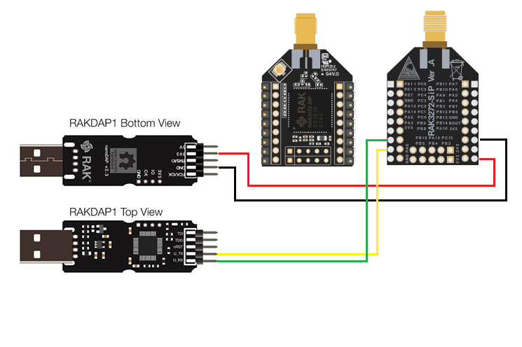 Figure 1: RAK3272-SiP Breakout Board to USB-Serial connection
-
Any serial communication tool can be used; but, it is recommended to use the RAK Serial Port Tool.
-
Configure the serial communication tool by selecting the proper port detected by the computer and configure the link as follows:
- Baud Rate: 115200 baud
- Data Bits: 8 bits
- Stop Bits: 1 stop bit
- Parity: NONE
RAK3272-SiP Breakout Board Configuration for LoRaWAN or LoRa P2P
To use the RAK3272-SiP breakout board as a LoRa P2P module or a LoRaWAN end-device, the module must be configured, and the necessary parameters set by sending AT commands. You can configure the RAK3272-SiP in the following ways:
- LoRaWAN End-Device: Set up the RAK3272-SiP breakout board as a LoRaWAN IoT device.
- LoRa P2P: Enable point-to-point communication between two RAK3272-SiP breakout board modules.
Configure RAK3272-SiP Breakout Board as LoRaWAN End-Device
To enable the RAK3272-SIP breakout board as a LoRaWAN end-device, a device must be registered first in the LoRaWAN network server. This guide will cover both TTN and Chirpstack LoRaWAN network servers and the associate AT commands for the RAK3272-SIP breakout board.
Connect to The Things Network (TTN)
This section shows how to connect the RAK3272-SiP Breakout Board to the TTN platform.
For this guide, ensure you have a functioning gateway connected to TTN or are within the coverage area of the TTN community network.
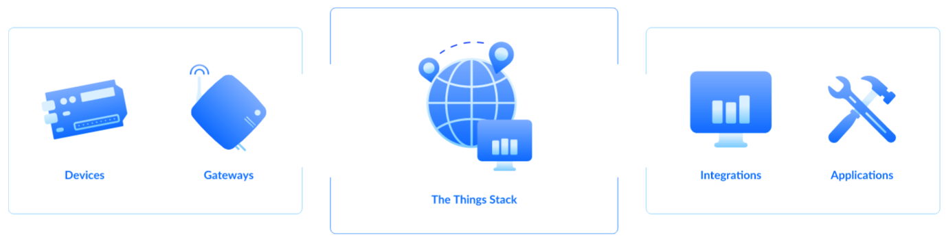 Figure 1: RAK3272-SiP in the context of the TTN
As shown in Figure 28, The Things Stack (TTN V3) is an open-source LoRaWAN Network Server suitable for global, geo-distributed public and private deployments, as well as for small, local networks. The architecture follows the LoRaWAN Network Reference Model for standards compliance and interoperability. This project is actively maintained by The Things Industries.
LoRaWAN is a protocol for low-power wide-area networks. It allows for large-scale Internet of Things deployments where low-powered devices efficiently communicate with Internet-connected applications over long-range wireless connections.
The RAK3272-SiP Breakout Board can be part of this ecosystem as a device, and the objective of this section is to demonstrate how simple it is to send data to The Things Stack using the LoRaWAN protocol. To achieve this, the RAK3272-SiP Breakout Board must be located inside the coverage of a LoRaWAN gateway connected to The Things Stack server.
Register for TTN and Create LoRaWAN Applications
- Visit The Things Network and create an account. After signing up, select a cluster.
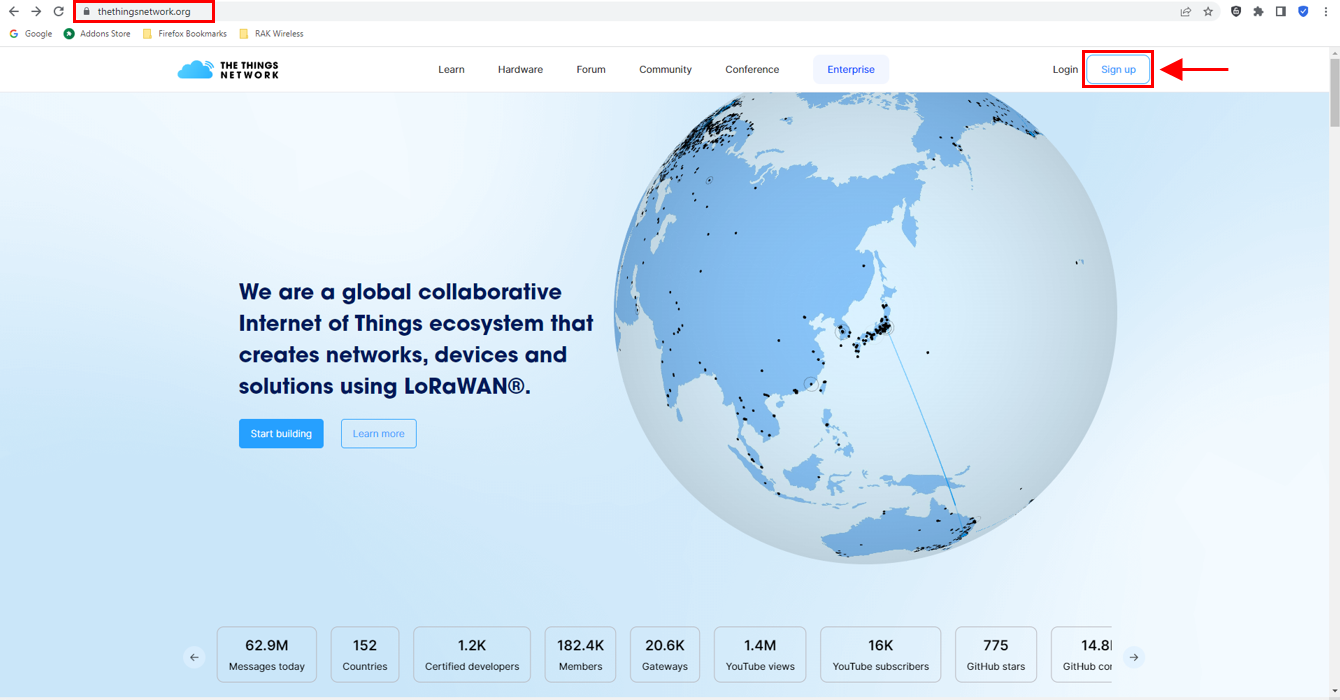 Figure 1: Sign up an account in TTN
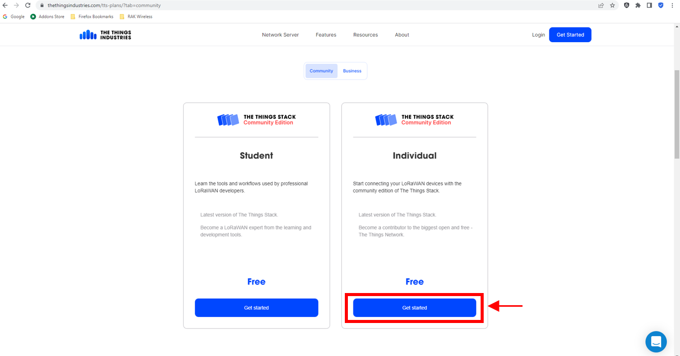 Figure 1: Sign up an account in TTN
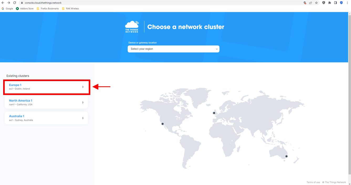 Figure 1: SelectCluster in TTN
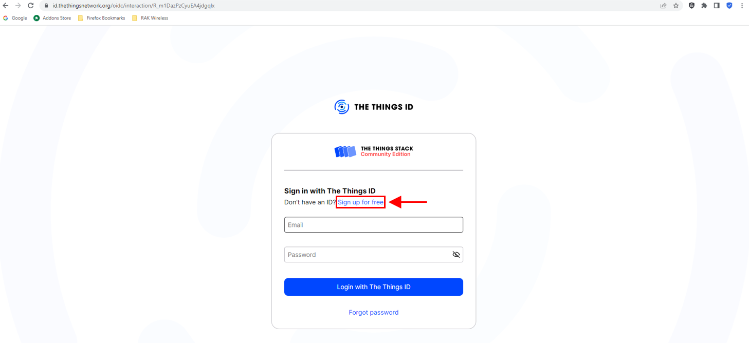 Figure 1: Sign up through the Things ID
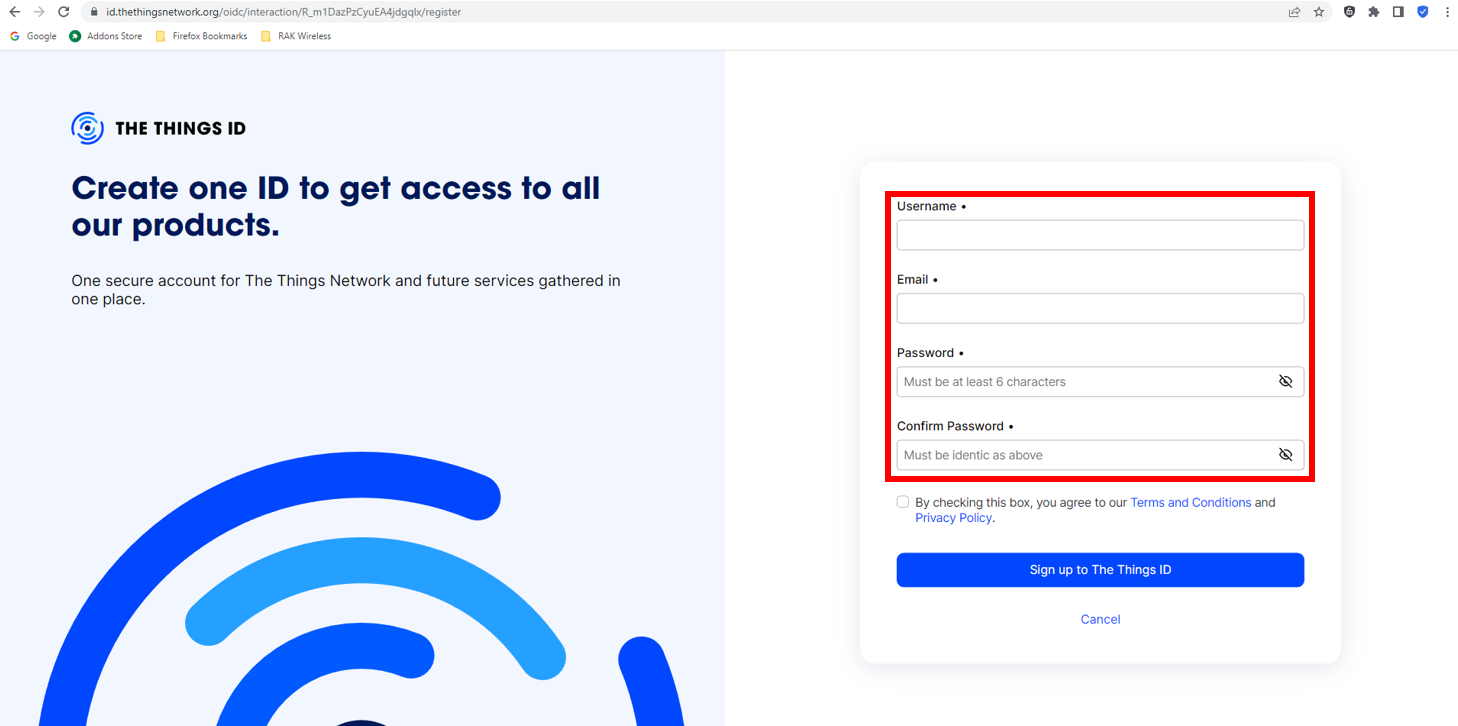 Figure 1: Creation of an account through the Things ID
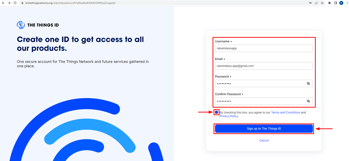 Figure 1: Creation of an account through the Things ID
If you already have a TTN V2 account, use the same login credentials. If not, create a new account.
- Click Create an application.
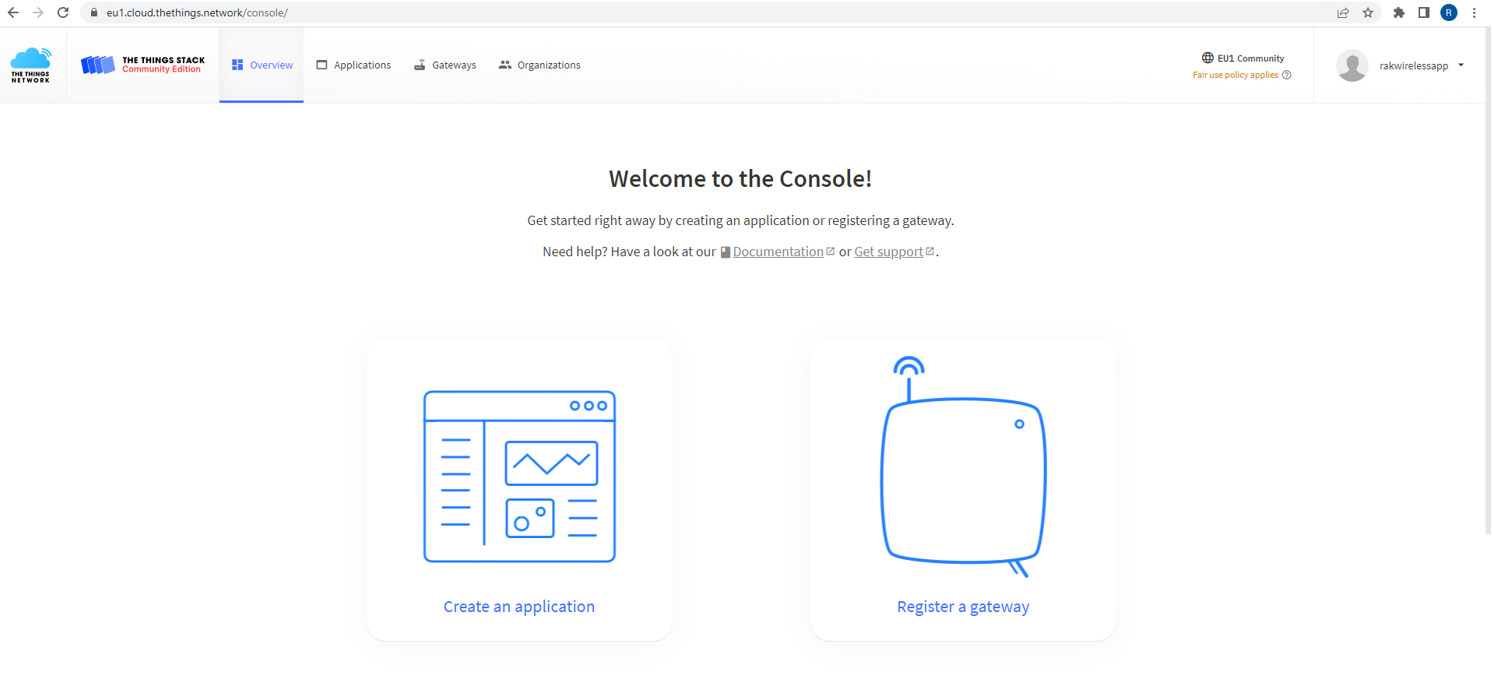 Figure 1: The Things Stack Platform
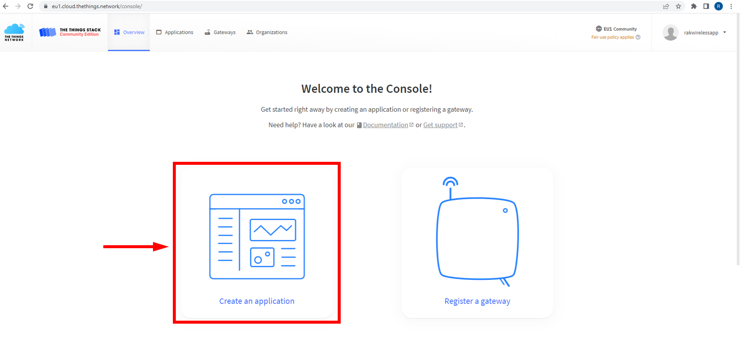 Figure 1: Create TTN application for your LoRaWAN devices
- To register an application, first enter the specific details and necessary information about the application, then click Create Application.
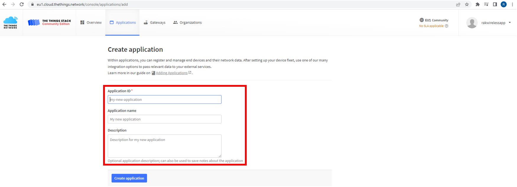 Figure 1: Details of the TTN application
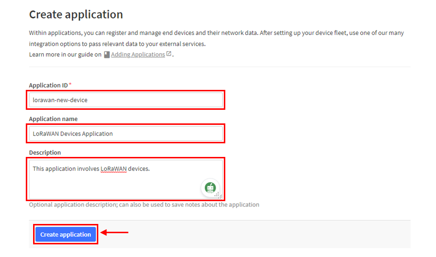 Figure 1: Details of the TTN application
If there were no errors in the previous step, you should now be on the application console page. The next step is to add end-devices to your TTN application.
LoRaWAN specifications enforce that each end-device has to be personalized and activated. Activation can be done either via Over-The-Air-Activation (OTAA) or Activation-By-Personalization (ABP).
TTN OTAA Device Registration
- Go to your application console to register a device. To start adding an OTAA end-device, click + Register end device, as shown in Figure 39.
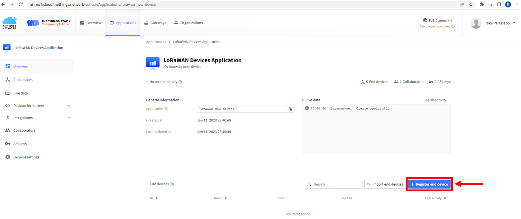 Figure 1: Register end device
- To register the board, click the Enter end device specifics manually.
 Figure 1: Enter end device specifics manually
- Configure the Frequency Plan, compatible LoRaWAN Version, and Regional Parameters Version supported by your device. Then, provide the JoinEUI credentials by entering zeroes.
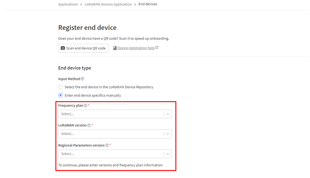 Figure 1: Setup for your device
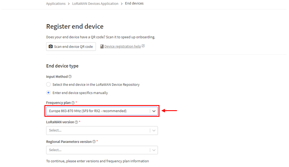 Figure 1: Setup for your device
 Figure 1: Setup for your device
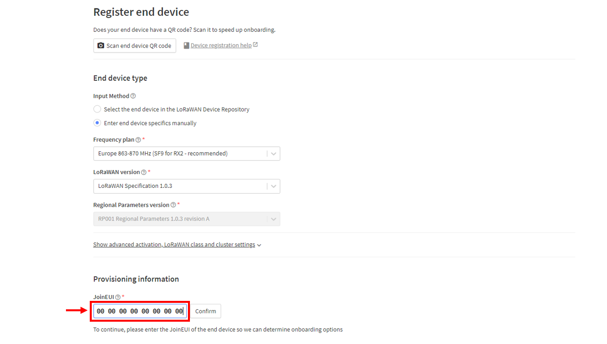 Figure 1: Setup for your device
- Click Show advanced activation, LoRaWAN class, and cluster settings. Configure the activation mode by selecting Over the Air Activation (OTAA) and set Additional LoRaWAN Class Capabilities to Class A only. Finally, click Confirm.
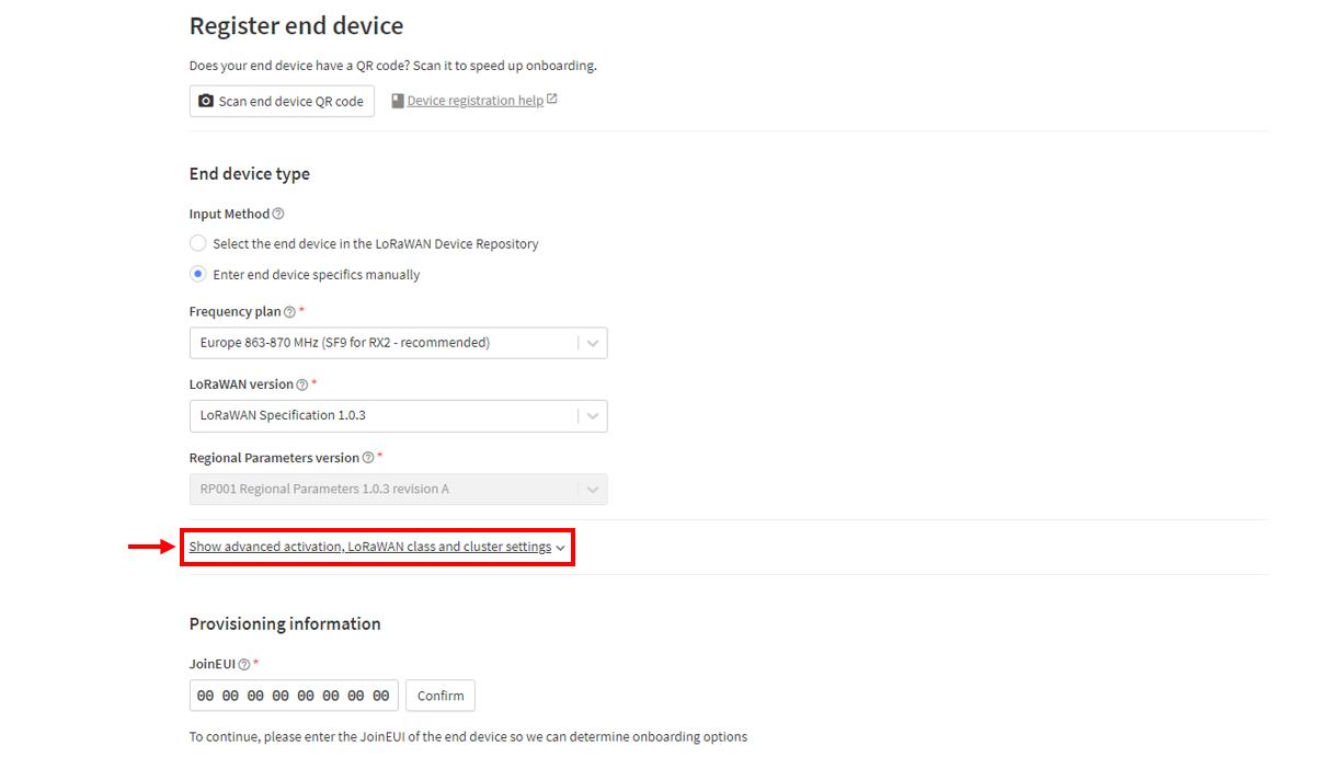 Figure 1: Setup for your device
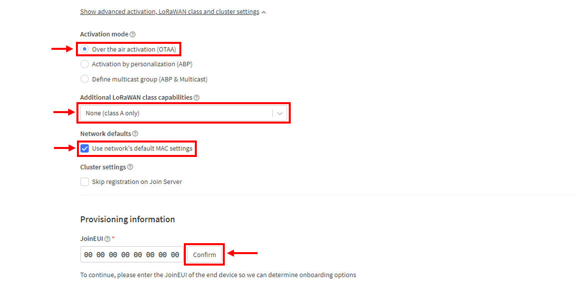 Figure 1: Setup for your device
- After completing the previous steps, enter the DevEUI credentials of your device into the DevEUI field. This will automatically generate the specific End Device ID for your board. Next, click Generate under AppKey in the Provisioning Information section. Finally, click Register End Device.
-
The AppEUI, DevEUI, and AppKey are hidden in this section because they are unique to each specific device. The DevEUI credential is unique to every RAK3272-SIP device. Additionally, you should generate your own AppEUI and AppKey credentials for your specific device and application.
-
The AppEUI is the same as JoinEUI
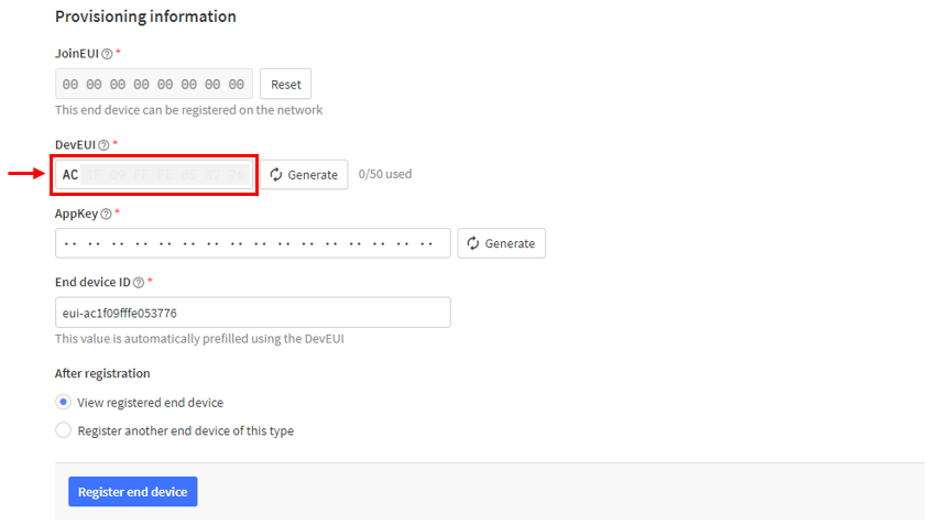 Figure 1: Setup for your device
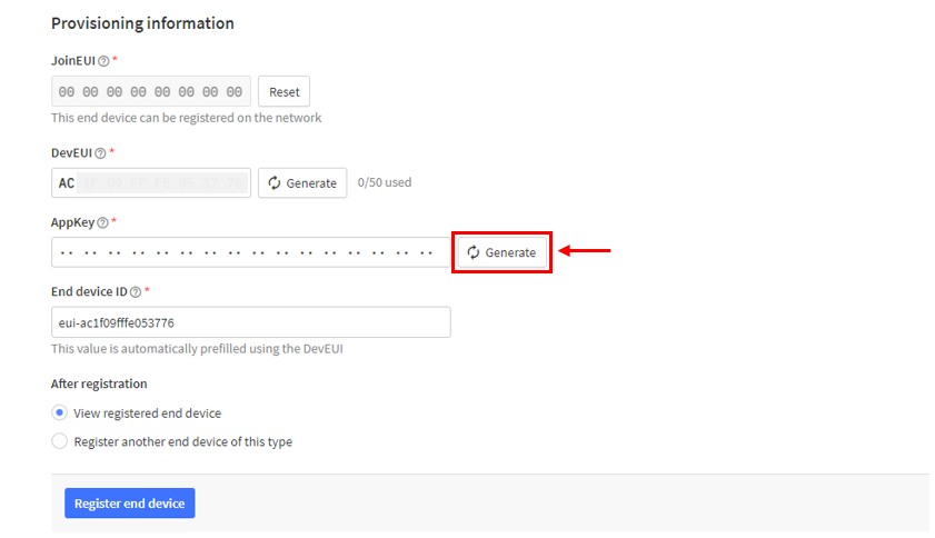 Figure 1: Setup for your device
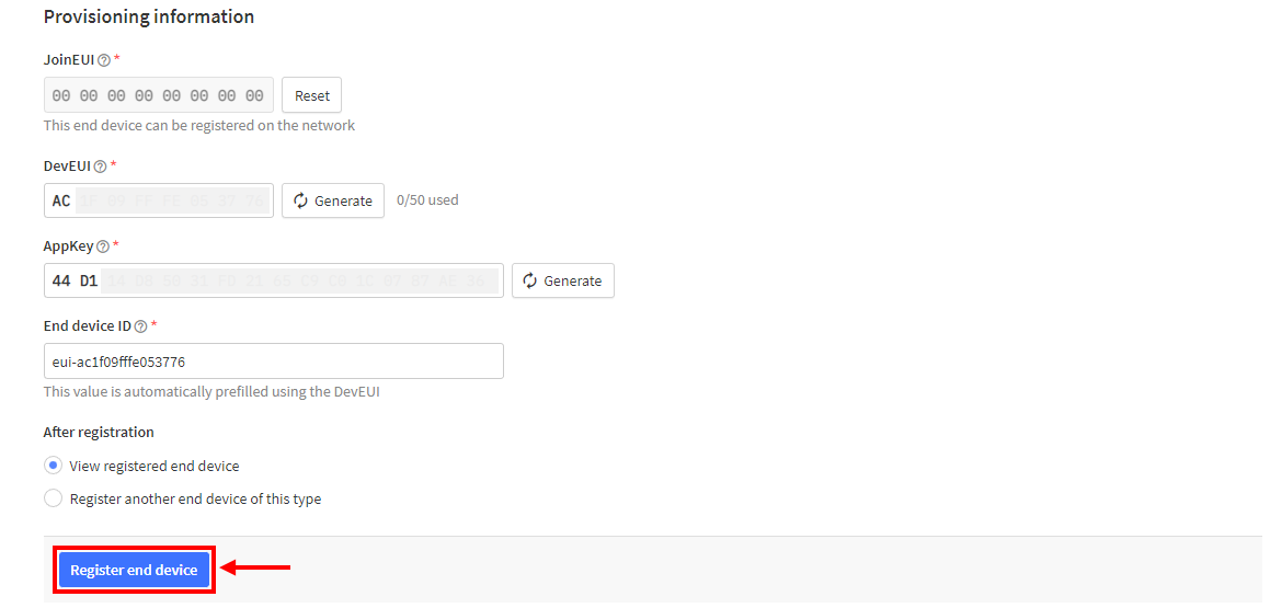 Figure 1: Register end device
- You should now be able to see the device on the TTN console, as shown in Figure 50.
-
The AppEUI, DevEUI, and AppKey are essential parameters for activating your LoRaWAN end-device via OTAA. The AppKey is hidden by default for security reasons but can be displayed by clicking the Show button. You can quickly copy these parameters using the Copy button.
-
The three OTAA parameters on the TTN device console are MSB by default.
-
These parameters are always accessible on the device console page, as shown in Figure 36.
 Figure 1: OTAA device successfully registered to TTN
OTAA Configuration for TTN
The RAK3272-SiP Breakout Board, equipped with a RAK3172-SiP module, can be configured for OTAA using WisToolBox, a software tool that supports the RAK3172-SiP module. WisToolBox automatically detects the RAK3172-SiP module when connected to a PC. Below are the options available in WisToolBox for performing OTAA configuration:
OTAA Configuration for TTN via WisToolBox UI
The RAK3172-SiP should have the correct OTAA credentials to connect to TTN. This can be done using WisToolBox UI. Below are the steps on setting up your RAK3172-SiP using WisToolBox.
- Connect your RAK3272-SiP module to the PC using the RAKDAP programmer, as described in the Connect to the RAK3272-SiP section. Then, open the WisToolBox application.
- Click the CONNECT DEVICE button to launch the WisToolBox Dashboard.
 Figure 1: CONNECT DEVICE button
- Select the target port where your RAK3272-SIP is connected. Once the device is recognized, click CONNECT, as shown in Figure 53.
 Figure 1: Set up your device
 Figure 1: Set up your device
- After connecting, the RAK3172-SiP module will appear on the dashboard. Select it to proceed.
 Figure 1: Device seen from WisToolBox dashboard
- Click PARAMETERS
 Figure 1: Set up your device
- Click Global settings to set the network mode into LoRaWAN and join mode to OTAA. Make sure that the active region is using EU868 for this configuration. If you wish to work on other regional bands, you can choose among active regions based on your location.
- LoRa network mode: LoRaWAN
- LoRaWAN join mode: OTAA
- LoRaWAN region: EU868
 Figure 1: Global settings
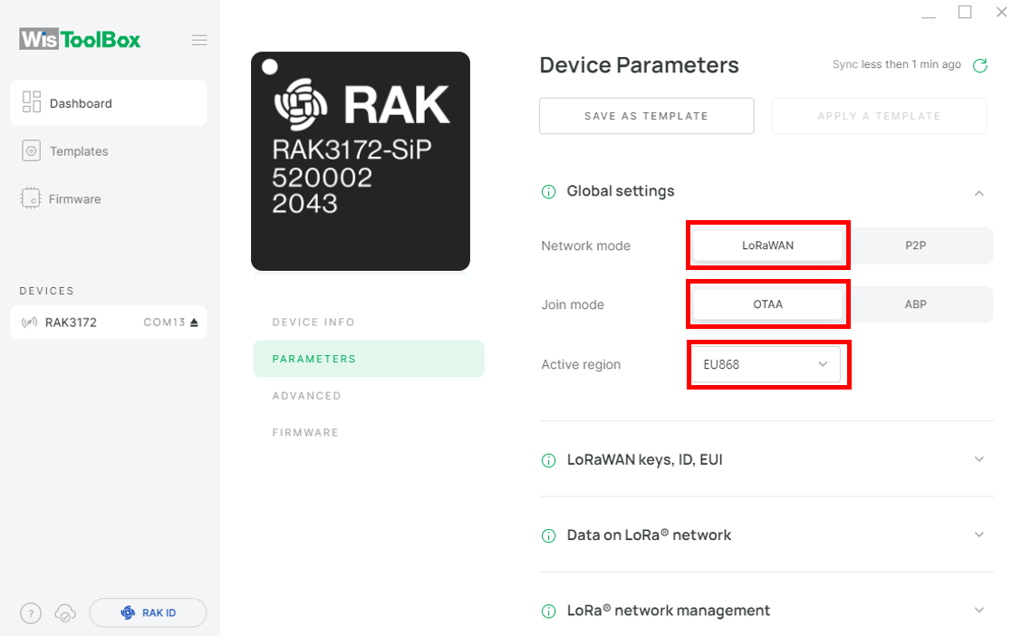 Figure 1: Global settings
- Click LoRaWAN keys, ID, EUI to configure the Application EUI (AppEUI), Application key (AppKey) and Device EUI (DevEUI).
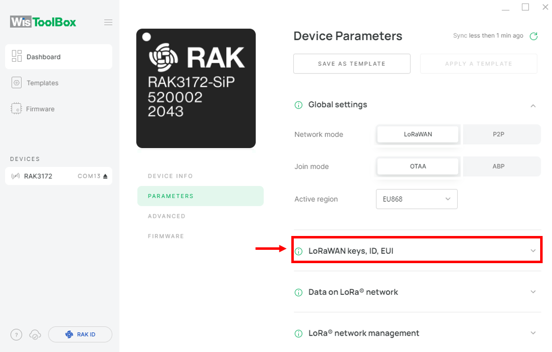 Figure 1: LoRaWAN keys, ID, EUI
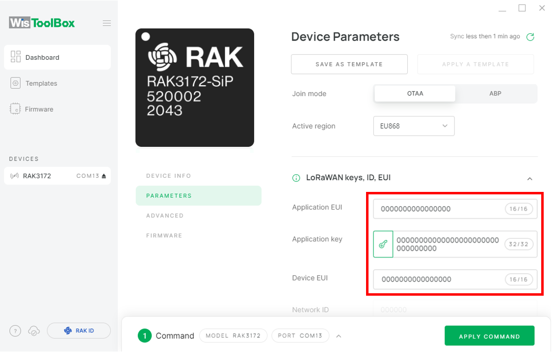 Figure 1: Set up your device
- Return to the TTN Console where your RAK3172 End Device was previously created. Copy all the credentials, including AppEUI, DevEUI, and AppKey. Enter these credentials into the WisToolBox dashboard. Once the credentials are correctly entered, click APPLY COMMAND to update your device, as shown in Figure 67.
The AppEUI, DevEUI, and AppKey are hidden in this section as these are unique from a specific device.
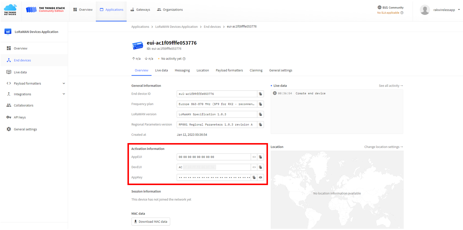 Figure 1: You created an OTAA device from your console
- For Application EUI (AppEUI)
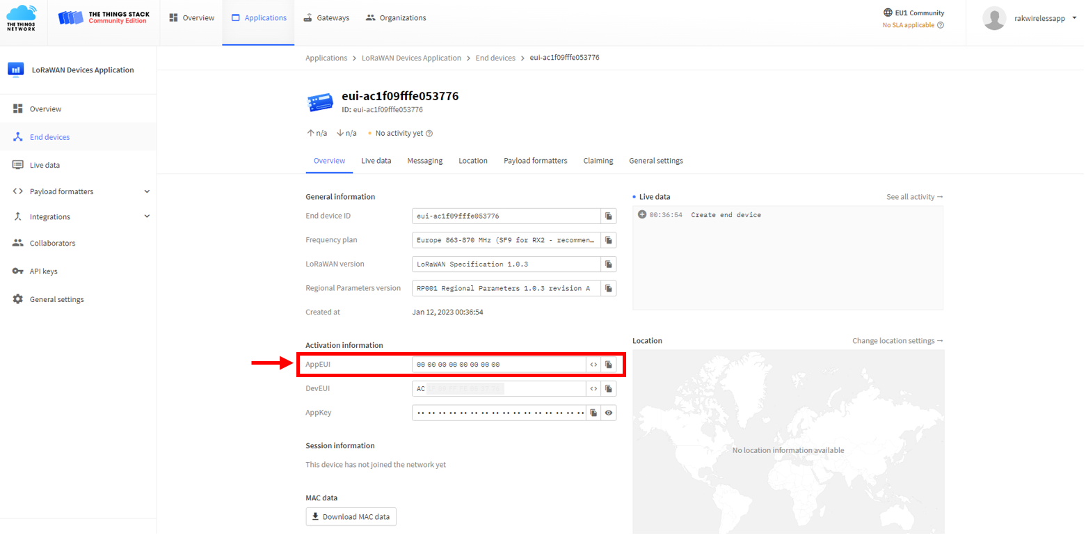 Figure 1: Copy the AppEUI credential from TTN to WisToolBox
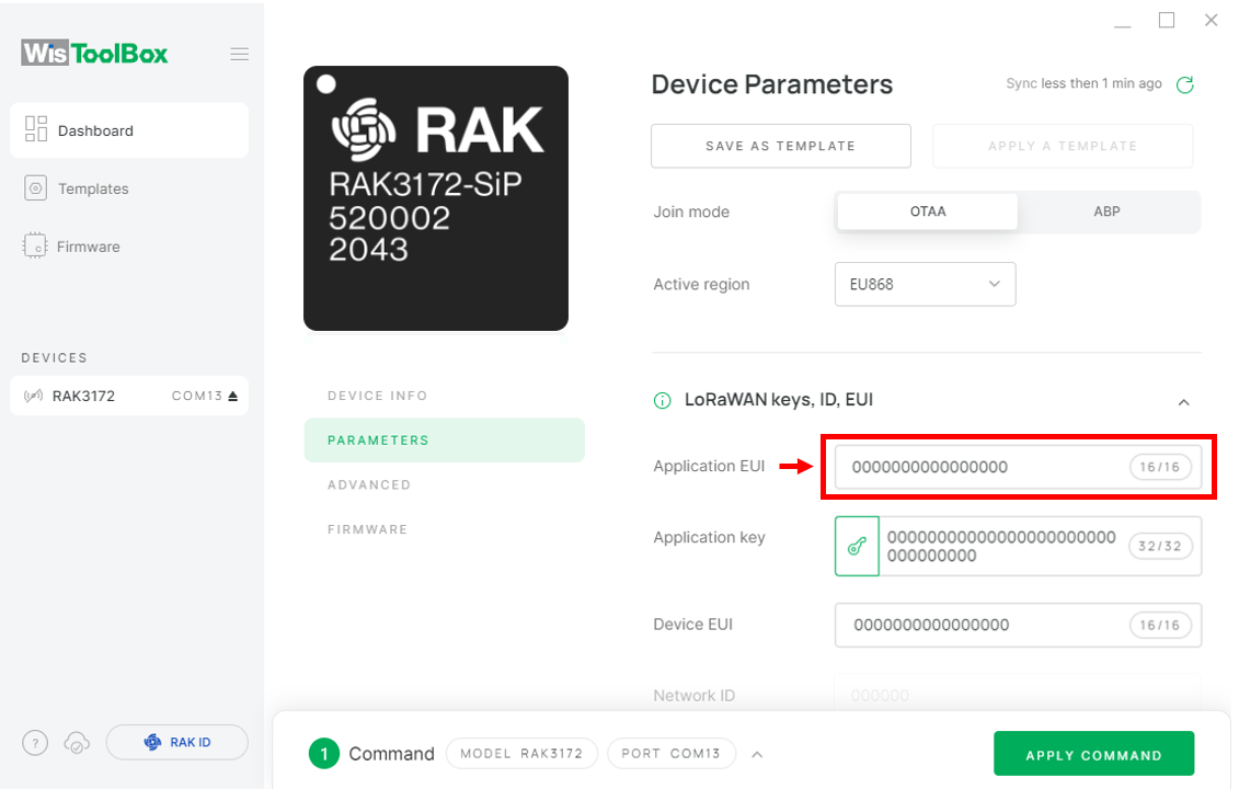 Figure 1: Copy the AppEUI credential from TTN to WisToolBox
- For Application key (AppKey)
 Figure 1: Copy the AppKey credential from TTN to WisToolBox
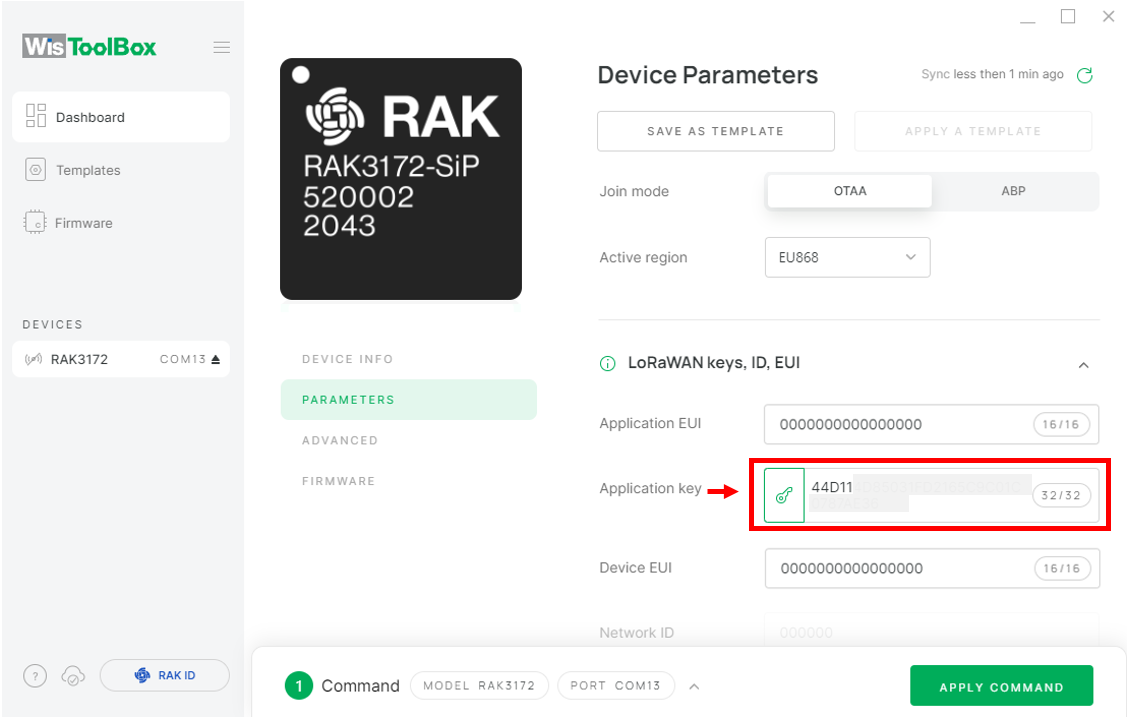 Figure 1: Copy the AppKey credential from TTN to WisToolBox
- For Device EUI (DevEUI)
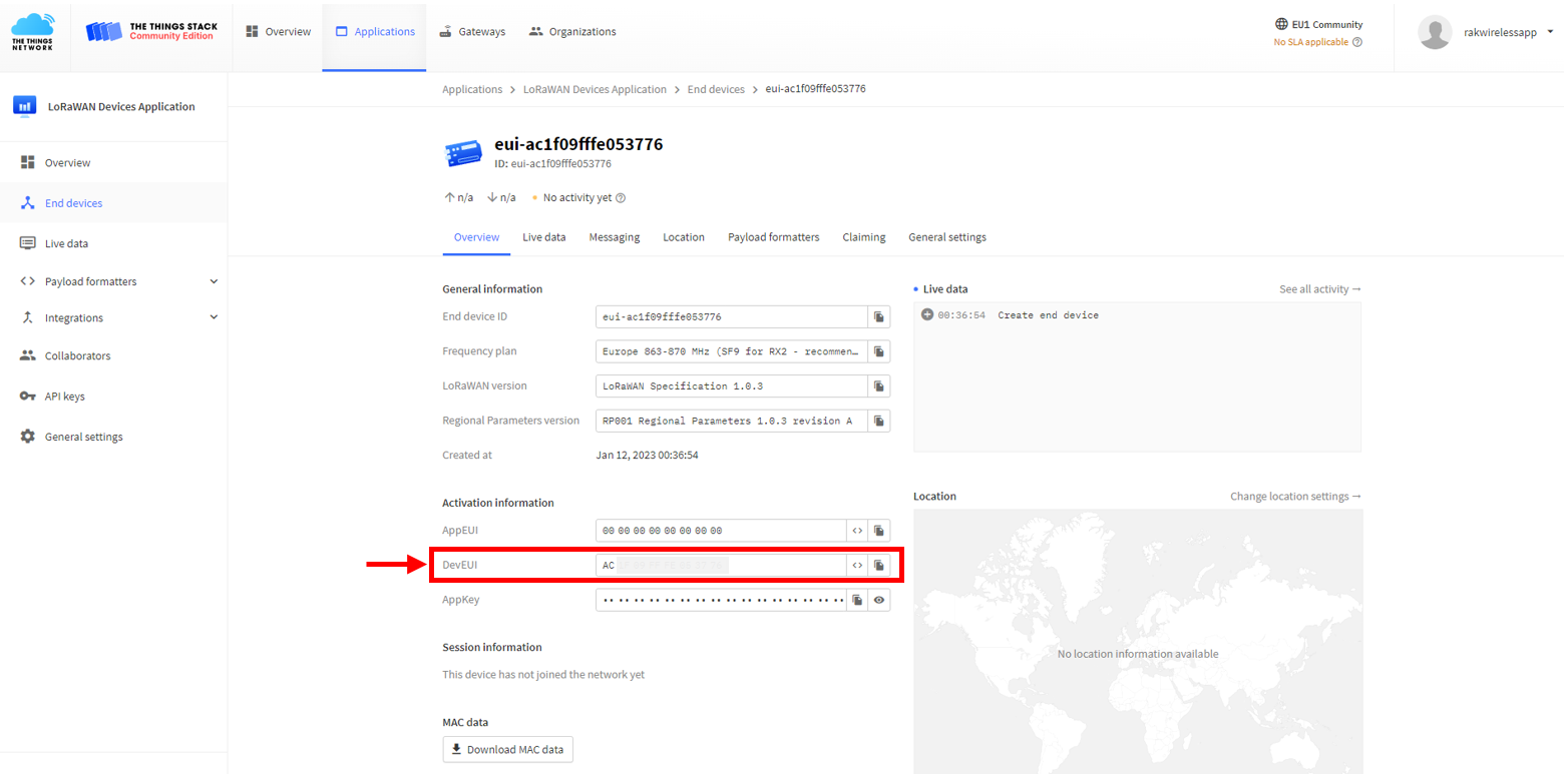 Figure 1: Copy the DevEUI credential from TTN to WisToolBox
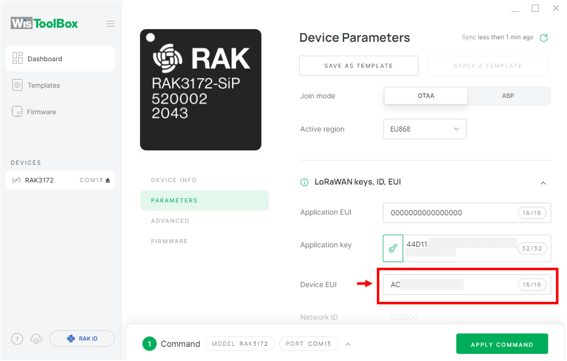 Figure 1: Copy the DevEUI credential from TTN to WisToolBox
- WisToolBox Dashboard
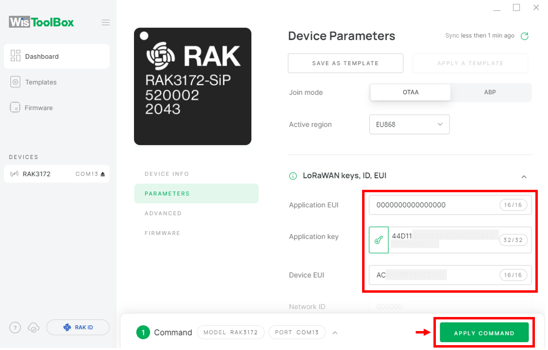 Figure 1: Used credentials from your console in WisToolBox dashboard
- After completing the configuration, a summary of the commands applied to your device will be displayed. Click CLOSE to finish.
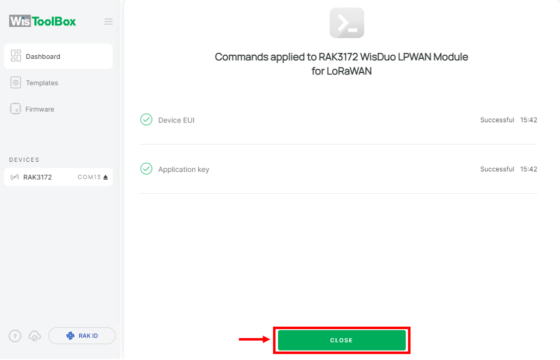 Figure 1: Summary of commands
- You will be returned to the dashboard, where the updated credentials of your device will be displayed.
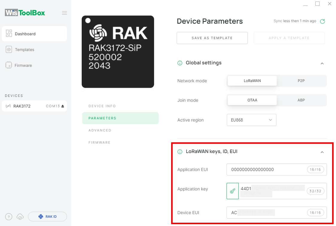 Figure 1: Successfully configured OTAA device via WisToolBox dashboard
- Navigate to Data on LoRa Network under PARAMETERS in WisToolBox. Click JOIN NETWORK under LoRaWAN Join Settings.
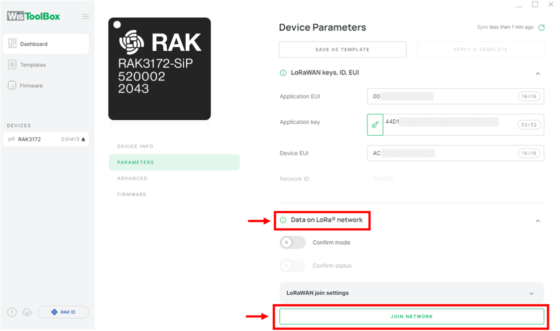 Figure 1: Join mode of your OTAA device
- Wait a few seconds for a notification confirming that your OTAA device has joined the TTN server.
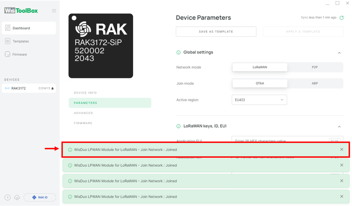 Figure 1: OTAA device successfully joined the TTN server
- Verify on the TTN Console to confirm that your device has successfully joined the TTN.
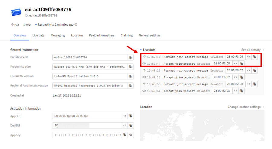 Figure 1: OTAA device successfully joined the TTN server
OTAA Configuration for TTN via WisToolBox Console
Here's another way of OTAA configuration using WisToolBox Console. Below are the steps on setting up the RAK3172-SiP using WisToolBox Console.
-
Connect your RAK3172-SiP with your chosen WisBlock base board to the PC via USB cable and open the WisToolBox application.
-
Click CONNECT DEVICE button to launch the WisToolBox Dashboard.
 Figure 1: CONNECT DEVICE
- Select your target port where your RAK3172-SiP is connected. Once recognized, click CONNECT as shown in Figure 75.
 Figure 1: Set up your device
 Figure 1: Set up your device
- Once done, RAK3172-SiP will appear in the dashboard then select it.
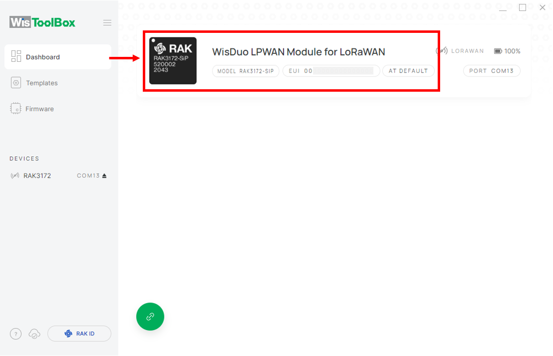 Figure 1: Device seen from WisToolBox dashboard
- Then click ADVANCED.
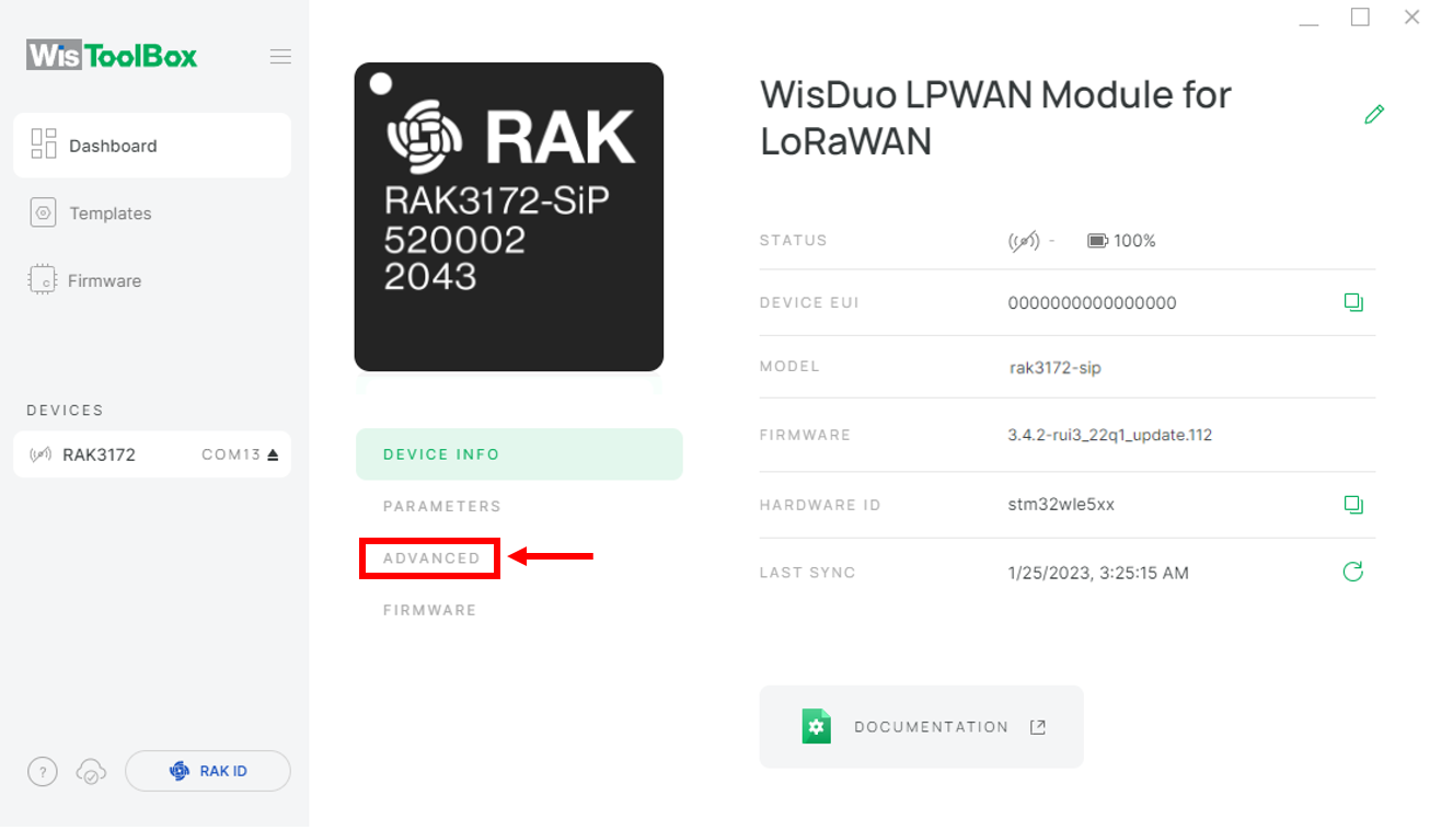 Figure 1: Set up your device
- Once done, click OPEN CONSOLE to do the configuration.
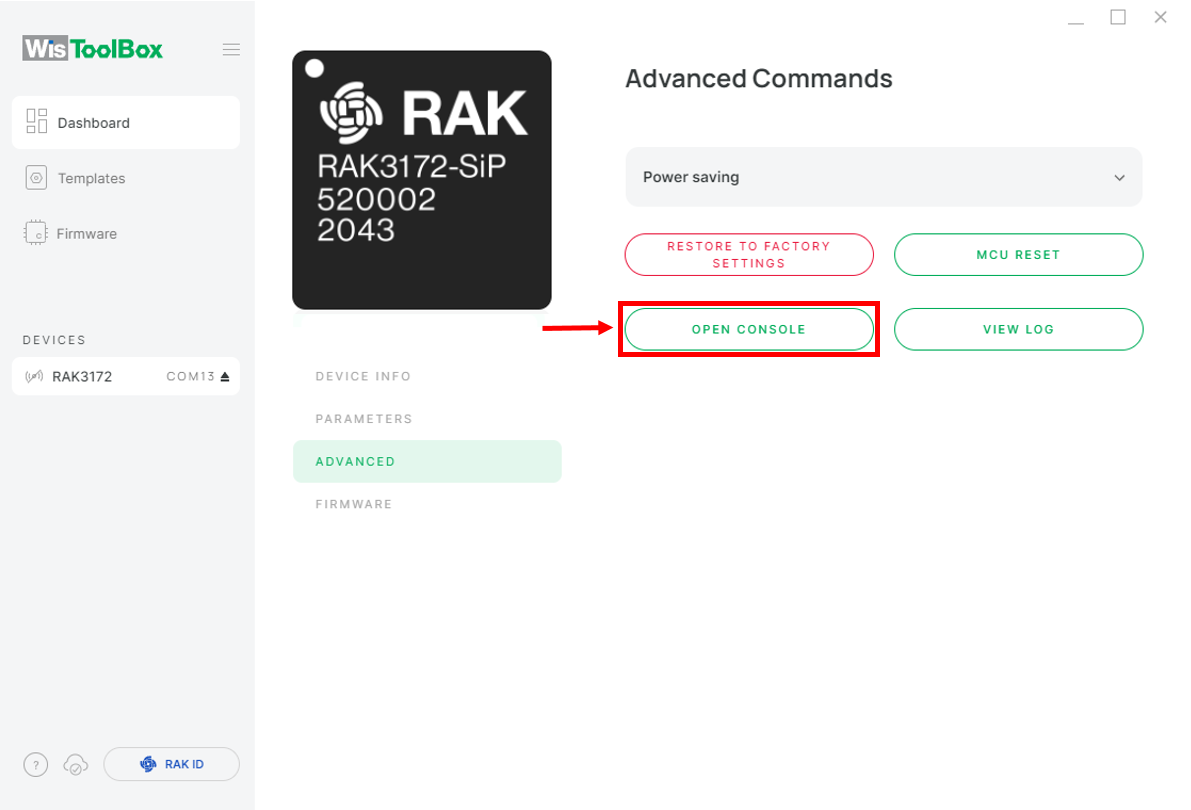 Figure 1: OPEN CONSOLE
 Figure 1: Open the Console terminal of WisToolBox
 Figure 1: Open the Console terminal of WisToolBox
- To begin the configuration, type ATE to enable command echoing during the setup process. Then press Enter.
It is recommended to start by testing the console and verify that the current configuration is working by sending these two AT commands:
AT
ATE
ATE is useful for tracking the commands and troubleshooting.
You will receive OK after entering the two commands. Once ATE is set, all the commands you input, along with their replies, will be displayed.
If you do not receive an OK or any reply, verify that the device is powered correctly. If using a USB port for power, ensure you are using a reliable USB cable.
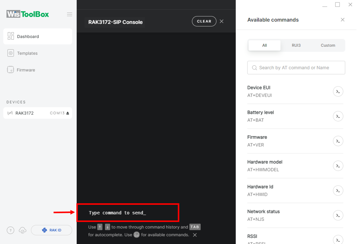 Figure 1: Set up your Console
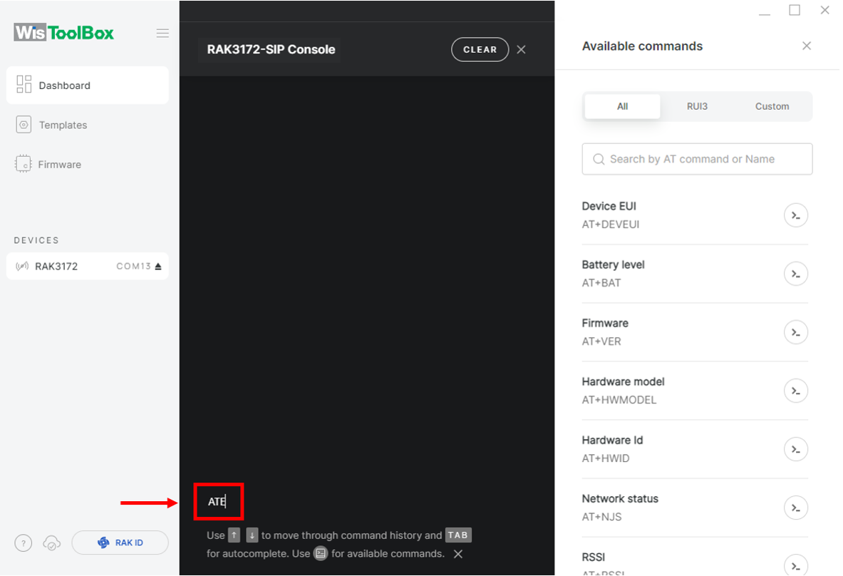 Figure 1: Set up your Console
 Figure 1: Set up your Console
- Next, configure the LoRaWAN join mode to OTAA. To check the current parameter, type AT+NJM? and press Enter in the console terminal.
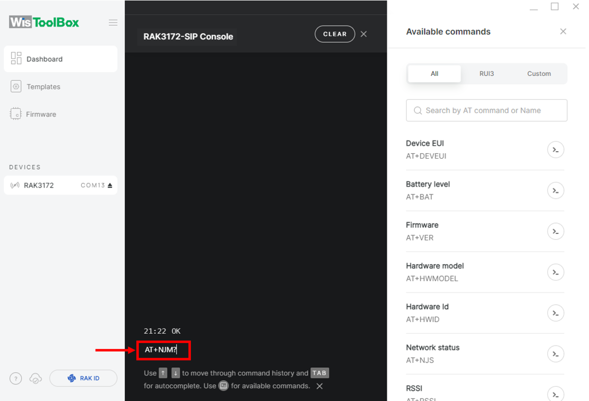 Figure 1: Set up your Console
 Figure 1: Set up your Console
- For OTAA, input AT+NJM=1 and press Enter.
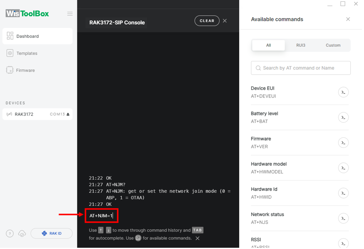 Figure 1: Set up your Console
- After configuring the join mode, set the LoRaWAN region according to your location. To check the current parameter, type AT+BAND? and press Enter in the console terminal. For EU868, input AT+BAND=4 and press Enter. If you need to configure a different regional band, refer to the list of band parameter options.
AT+BAND=4
-
Depending on the regional band, configure the sub-band of the RAK3172 to align with the gateway and LoRaWAN network server. This configuration is especially critical for regional bands such as US915, AU915, and CN470.
-
To configure channel masking for the sub-bands, use the
AT+MASKcommand, as detailed in the AT Command Manual. -
For example, to use sub-band 2, send the command
AT+MASK=0002.
List of band parameter options
| Code | Regional Band |
|---|---|
| 0 | EU433 |
| 1 | CN470 |
| 2 | RU864 |
| 3 | IN865 |
| 4 | EU868 |
| 5 | US915 |
| 6 | AU915 |
| 7 | KR920 |
| 8 | AS923-1 |
| 9 | AS923-2 |
| 10 | AS923-3 |
| 11 | AS923-4 |
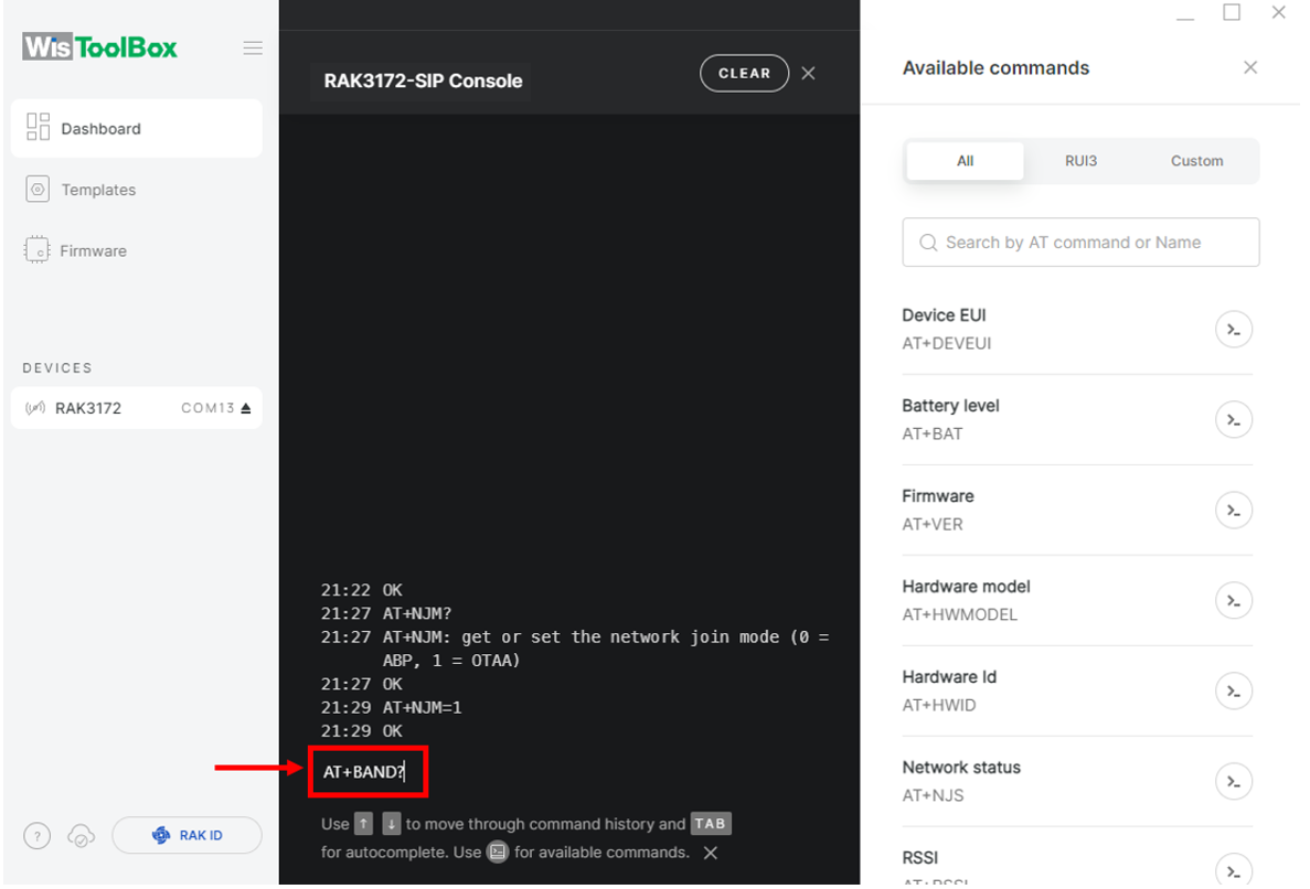 Figure 1: Set up your Console
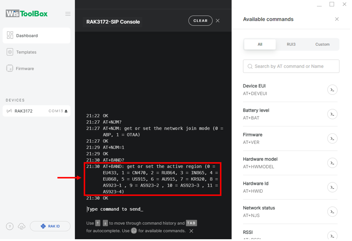 Figure 1: Set up your Console
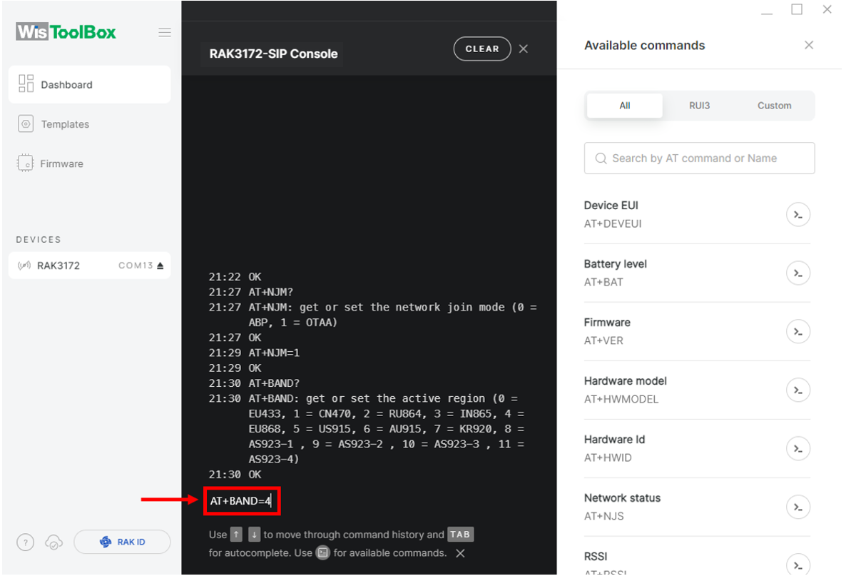 Figure 1: Set up your Console
- Return to the TTN console where your RAK3172 end device was created, copy the AppEUI credential, paste it into the WisToolBox console, and press Enter.
 Figure 1: Your created OTAA device from your TTN console
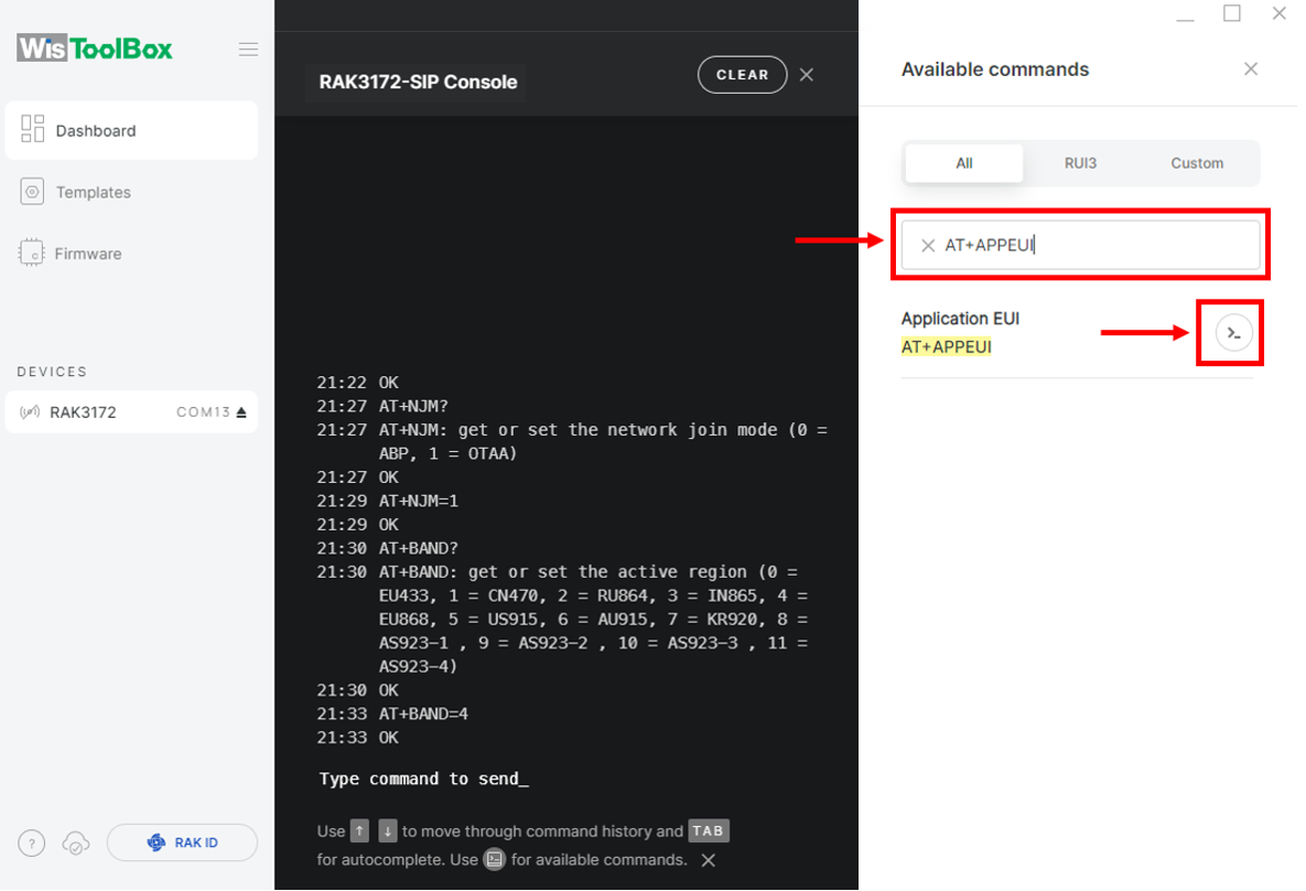 Figure 1: Set up your Console
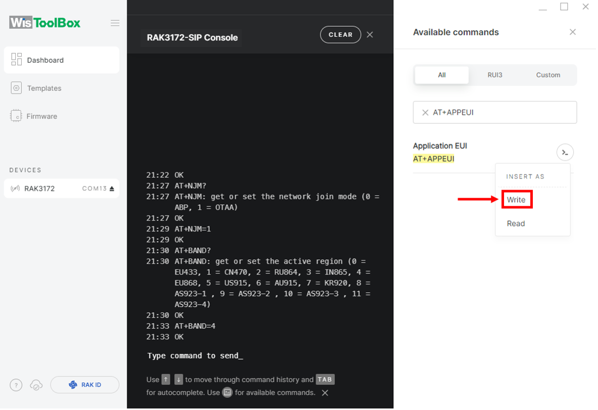 Figure 1: Set up your Console
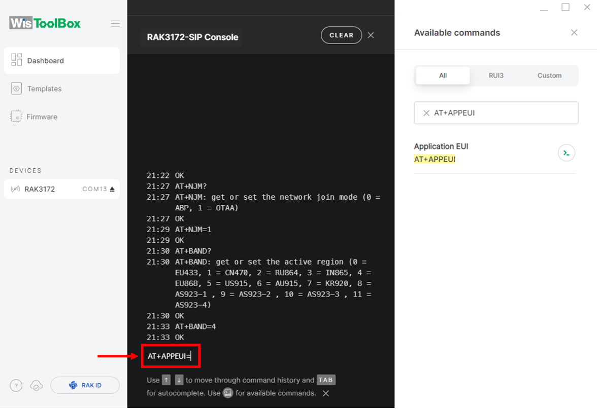 Figure 1: Set up your Console
 Figure 1: Copy the AppEUI credential from TTN to WisToolBox
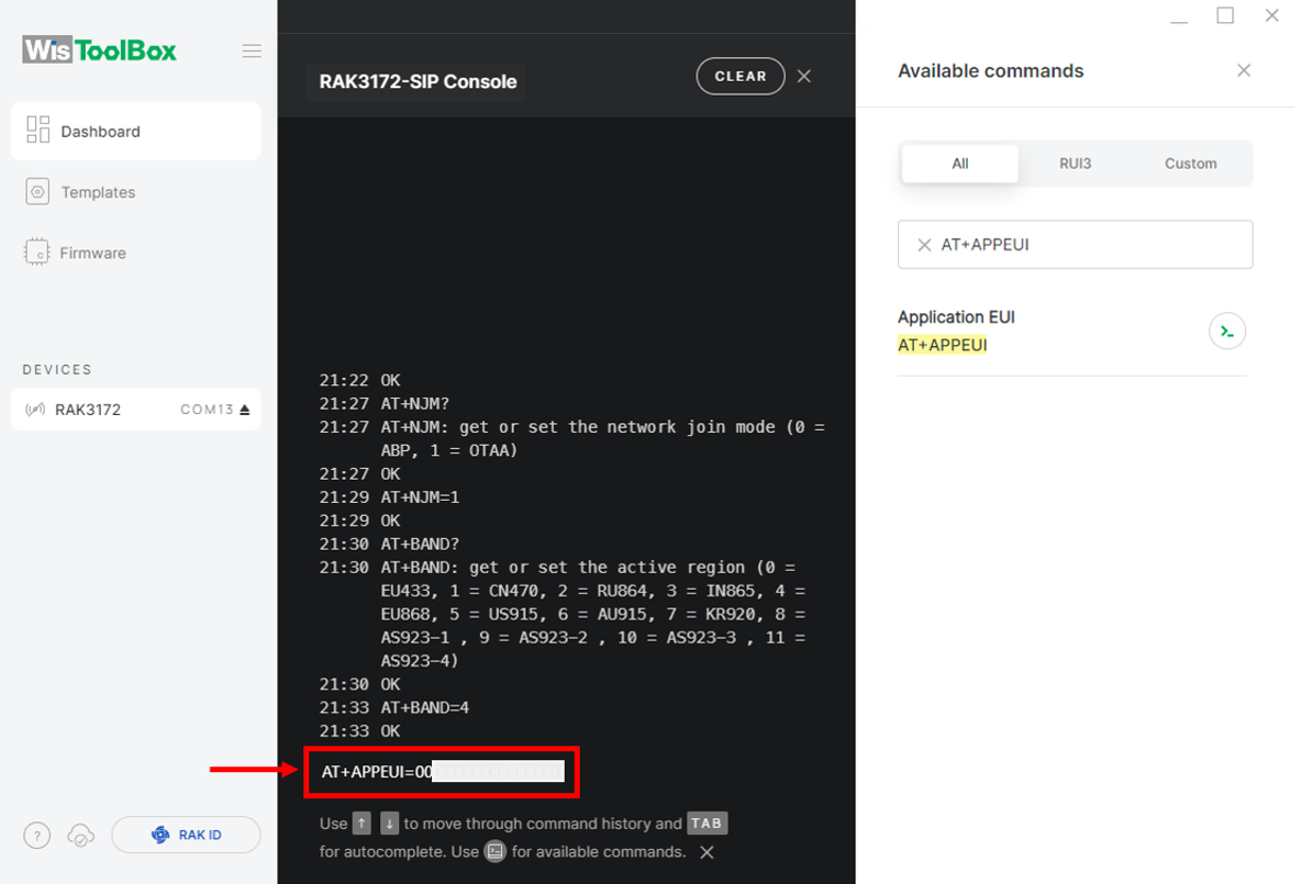 Figure 1: Set up your Console
- After completing the AppEUI configuration, repeat the same procedure for the Application Key (AppKey) and Device EUI (DevEUI).
- For Application key (AppKey)
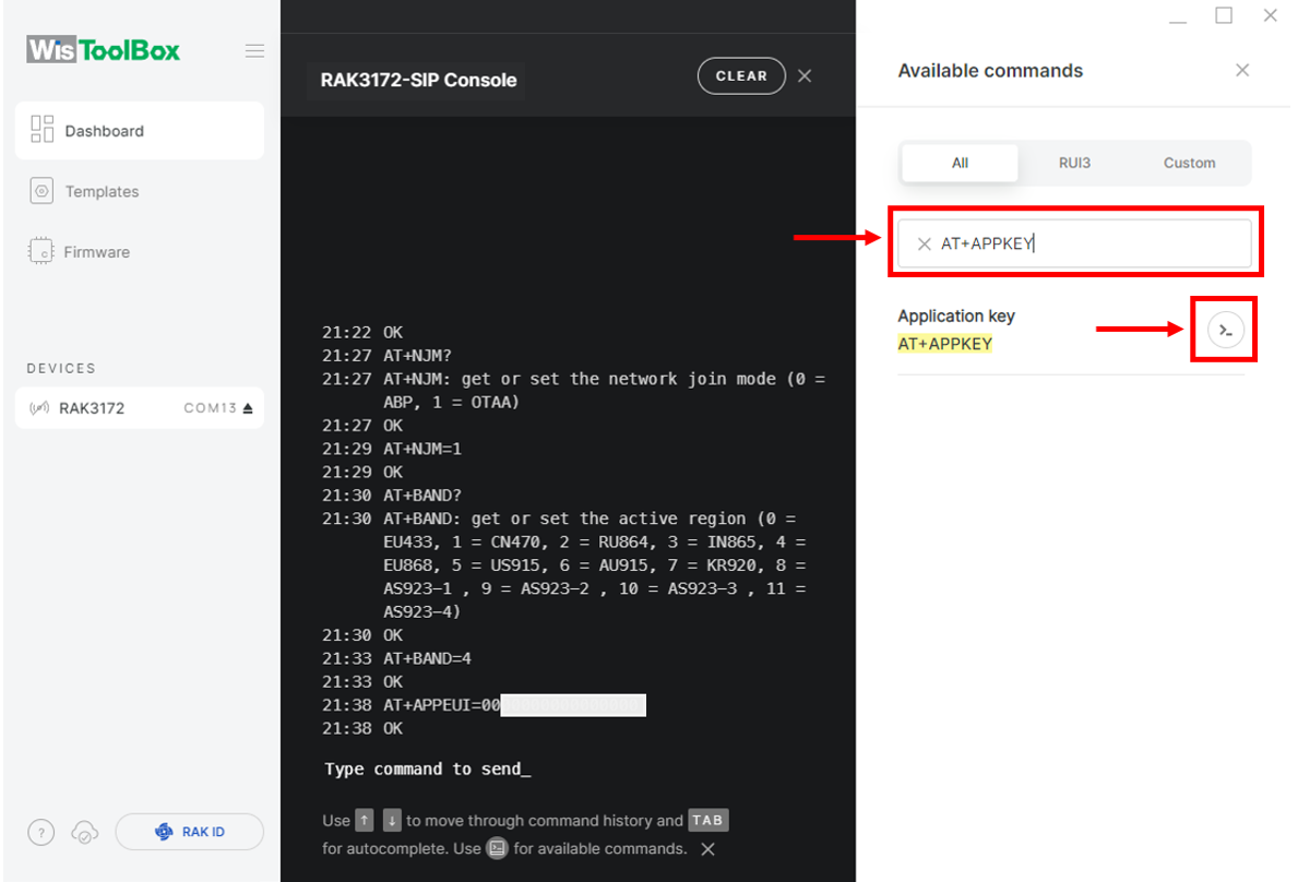 Figure 1: Set up your Console
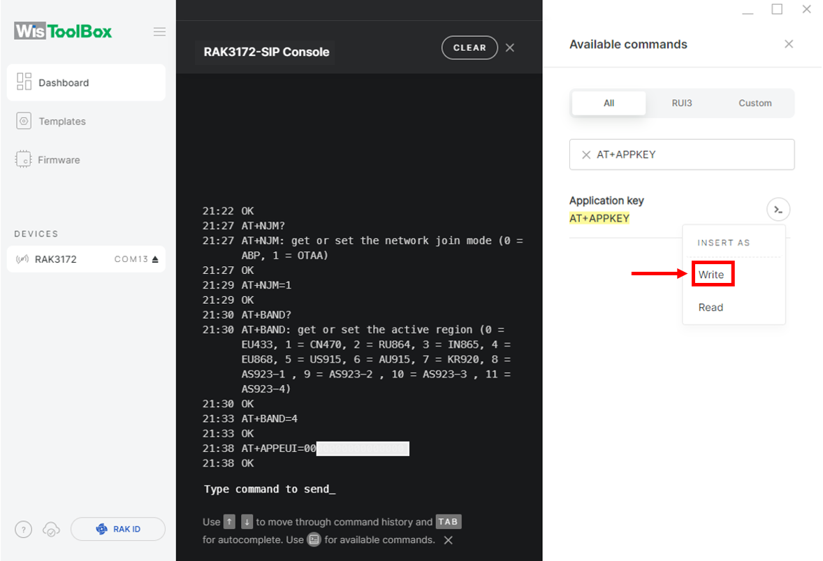 Figure 1: Set up your Console
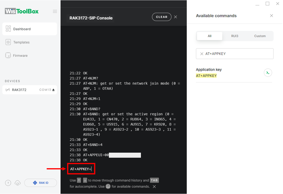 Figure 1: Set up your Console
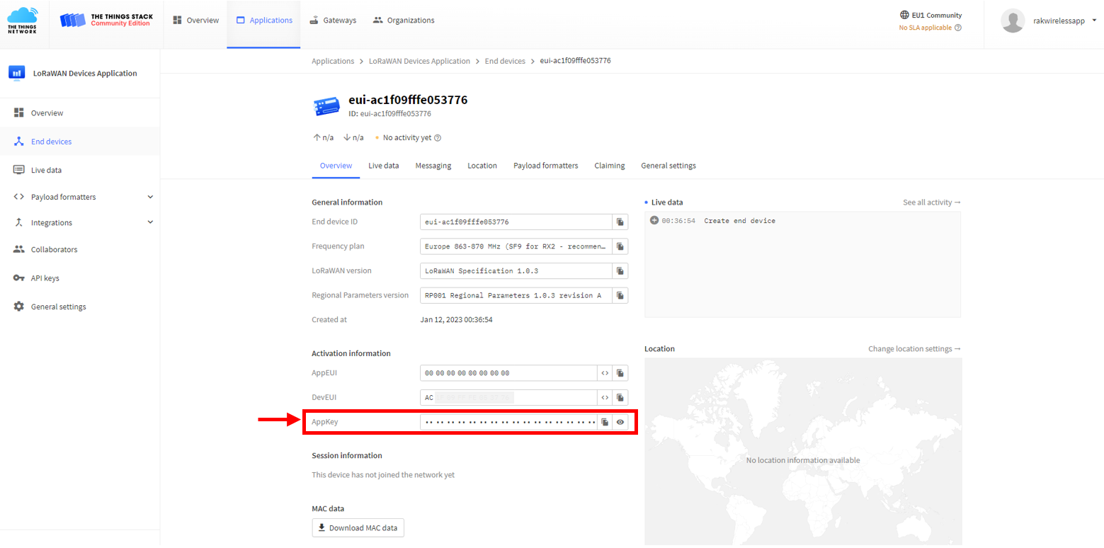 Figure 1: Copy the AppKey credential from TTN to WisToolBox
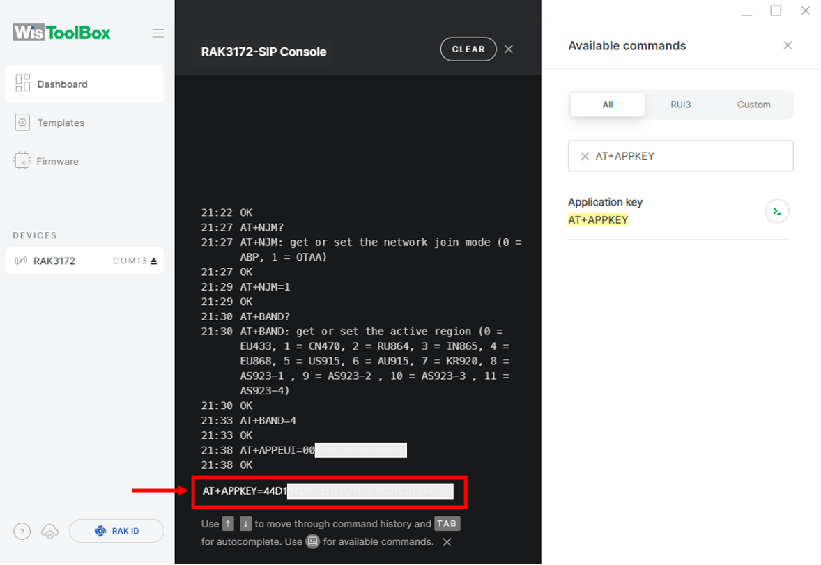 Figure 1: Set up your Console
- For Device EUI (DevEUI)
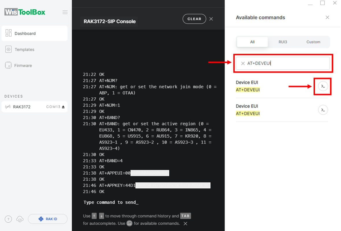 Figure 1: Set up your Console
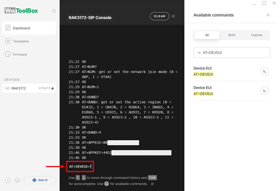 Figure 1: Set up your Console
 Figure 1: Copy the DevEUI credential from TTN to WisToolBox
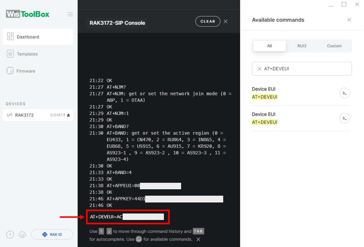 Figure 1: Set up your Console
- Click Dashboard to check the updated credentials of your OTAA device.
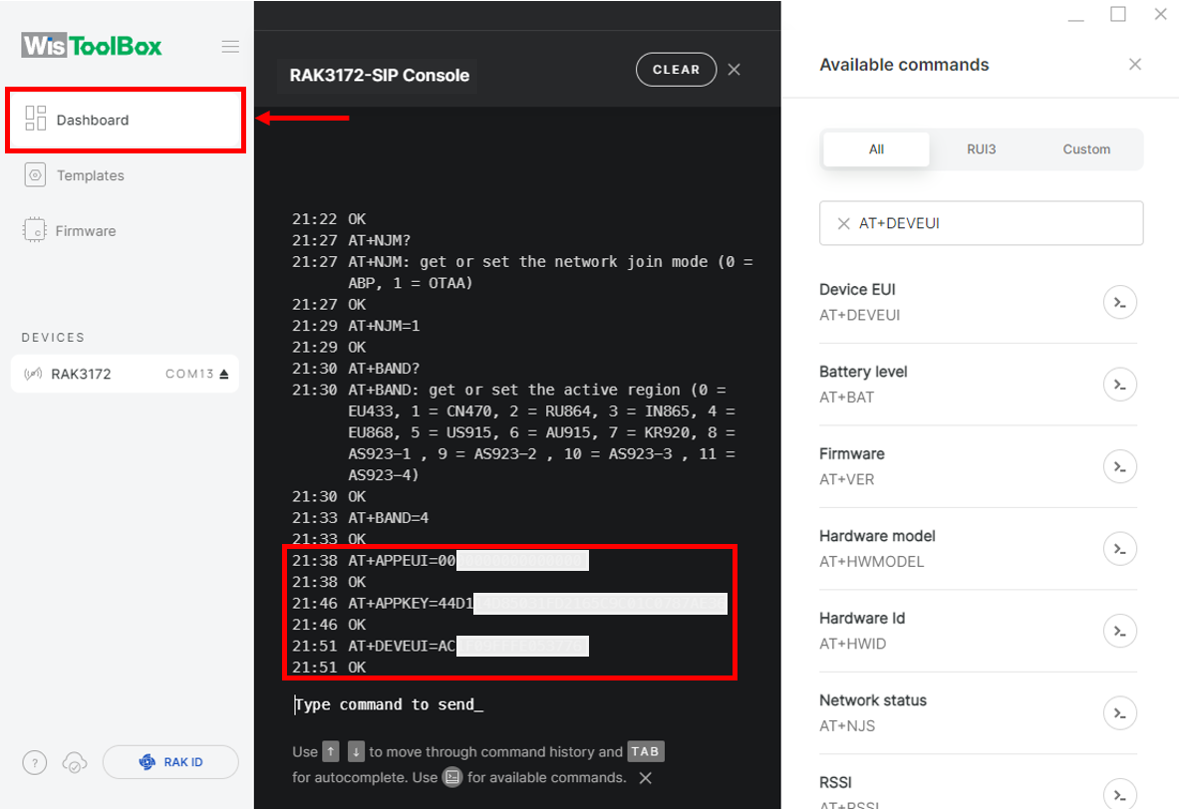 Figure 1: Set up your Console
 Figure 1: Set up your Console
- Click PARAMETERS to access the Global Settings and the LoRaWAN Keys, ID, EUI section. Verify that these fields have been updated.
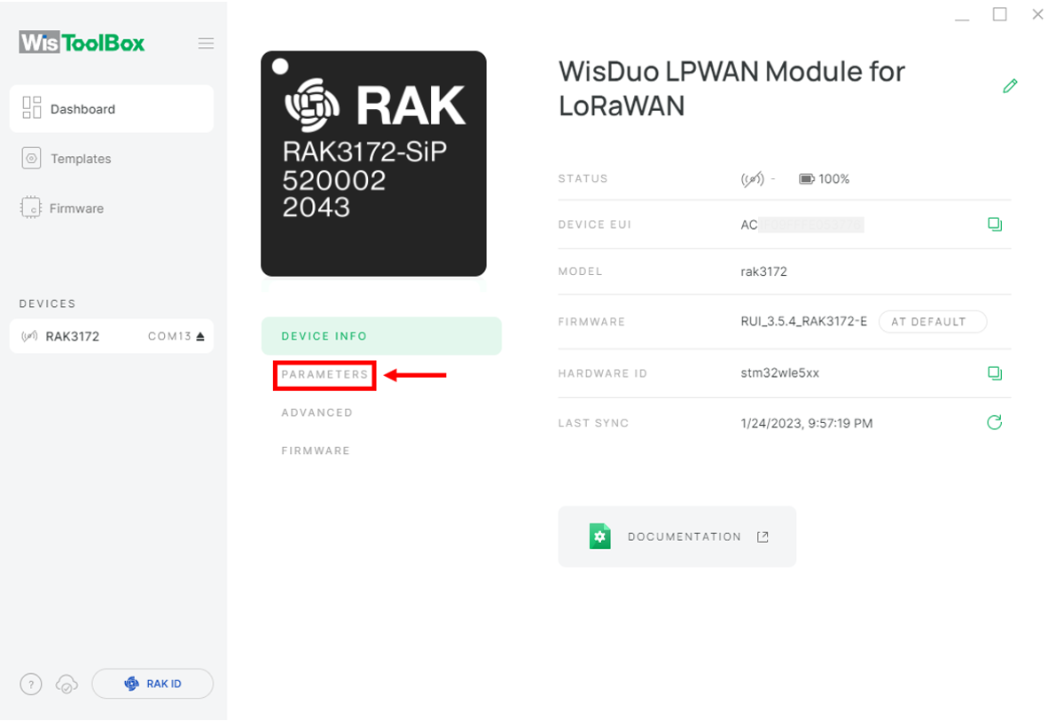 Figure 1: PARAMETERS
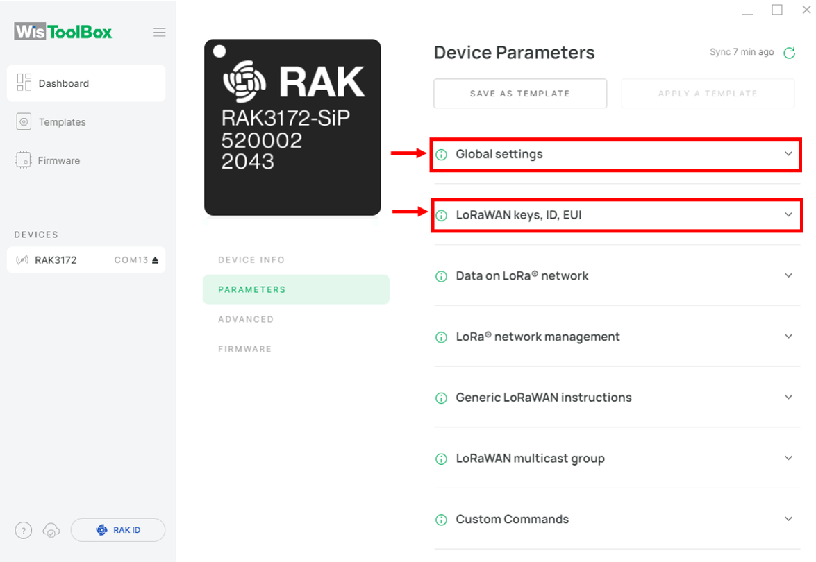 Figure 1: Global settings and LoRaWAN keys, ID, EUI
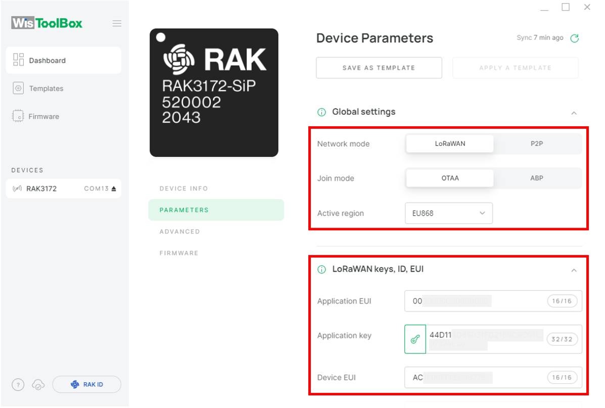 Figure 1: Global settings and LoRaWAN keys, ID, EUI details
- Return to the WisToolBox console, type AT+JOIN, edit it to AT+JOIN=1, and press Enter to join the network.
-
The
AT+JOINcommand parameters are optional. You can configure settings such as auto-join, reattempt interval, and the number of join attempts as needed for your application. If not configured, the command will use default parameter values. -
Both
AT+JOINandAT+JOIN=1share the same functionality of attempting to join the network.
Join command format: AT+JOIN=w:x:y:z
| Parameter | Description |
|---|---|
| w | Join command - 1: joining, 0: stop joining. |
| x | Auto-join config - 1: auto-join on power-up, 0: no auto-join |
| y | Reattempt interval in seconds (7-255) - 8 is the default. |
| z | Number of join attempts (0-255) - 0 is default. |
After 5 or 6 seconds, if the request is successfully received by a LoRa gateway, you should see +EVT:JOINED status reply, as shown in the figure below:
If the OTAA device fails to join, ensure the following:
- Verify that your device is within the coverage of a functioning LoRaWAN gateway configured to connect to TTN.
- Confirm the accuracy of your OTAA parameters using the commands:
AT+DEVEUI=?AT+APPEUI=?AT+APPKEY=?
- Ensure the device antenna is properly connected.
After addressing these points, attempt to join the network again.
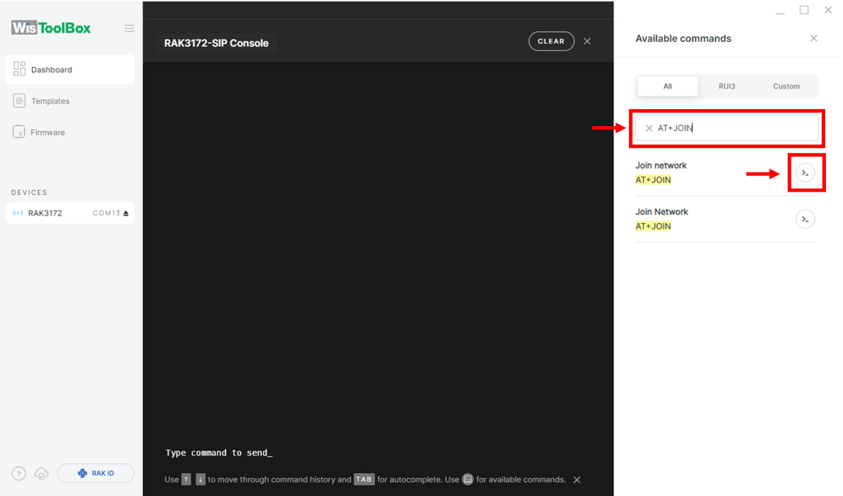 Figure 1: Join mode using WisToolBox Console
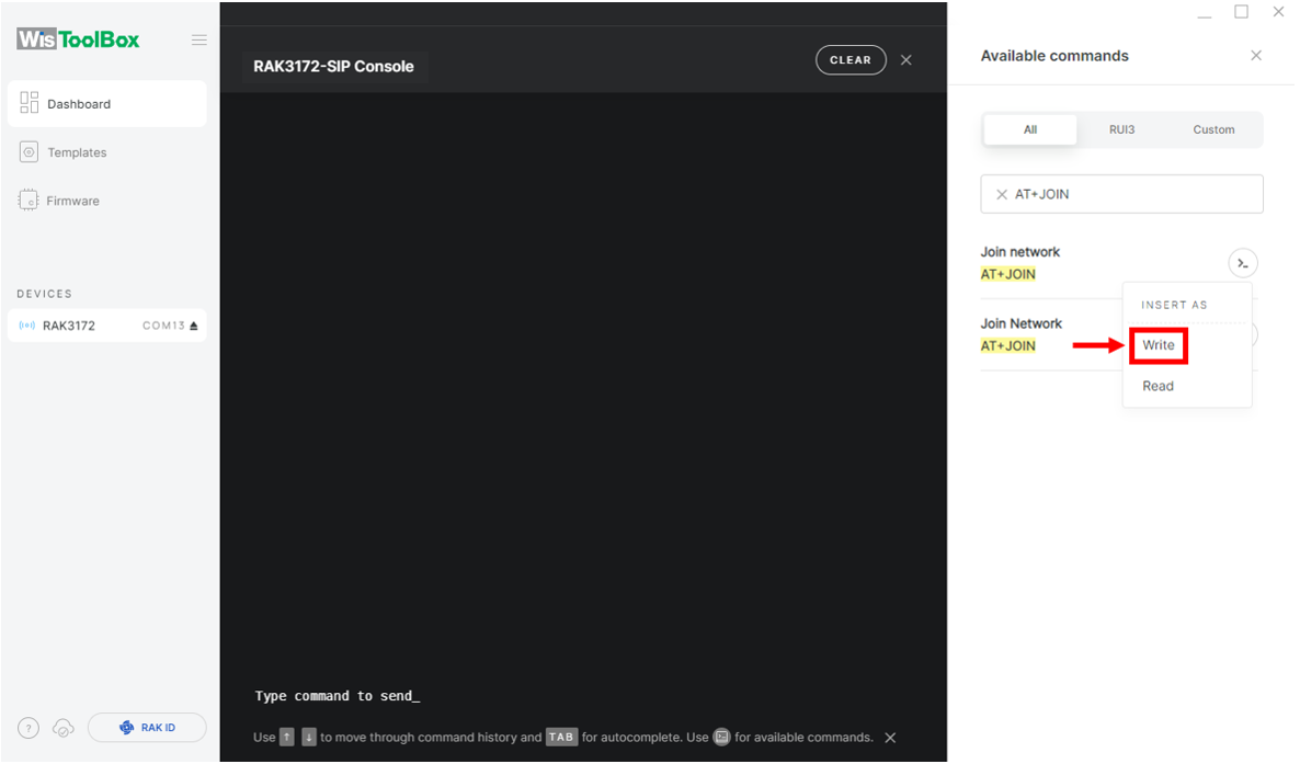 Figure 1: Join mode using WisToolBox Console
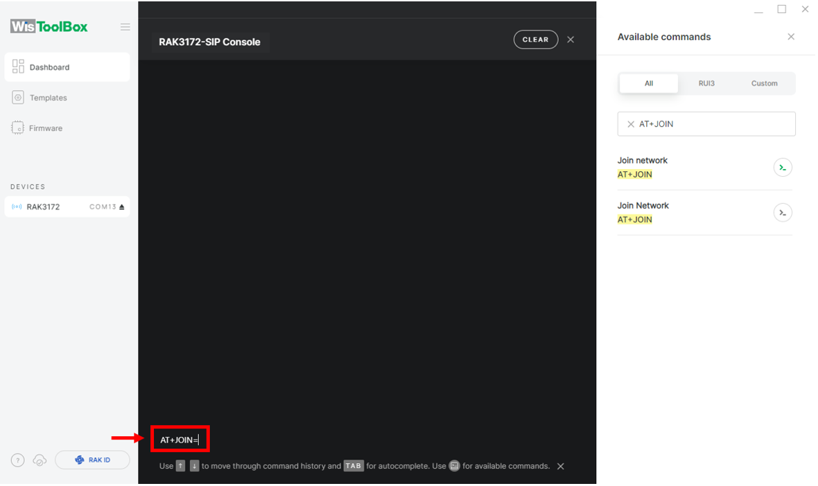 Figure 1: Join mode using WisToolBox Console
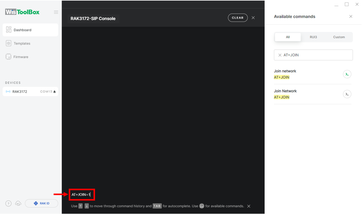 Figure 1: Join mode using WisToolBox Console
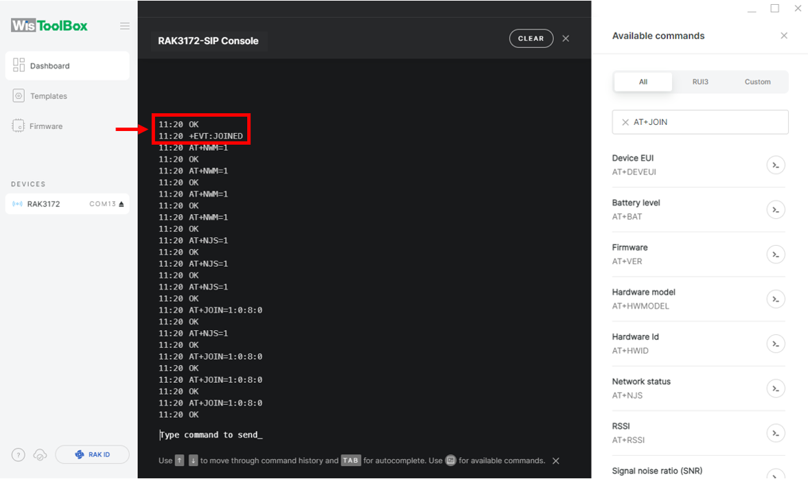 Figure 1: OTAA device successfully joined the network
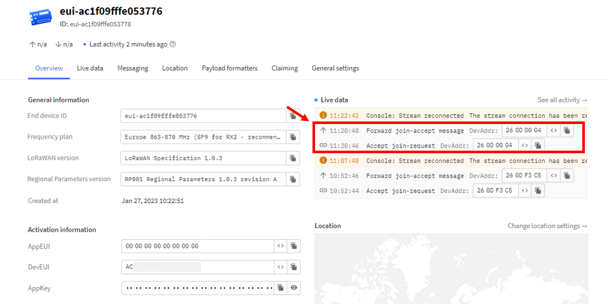 Figure 1: OTAA device successfully joined the network
- With the end-device properly joined the TTN, try to send some payload. Send command format:
AT+SEND=<port>:<payload>
AT+SEND=2:12345678
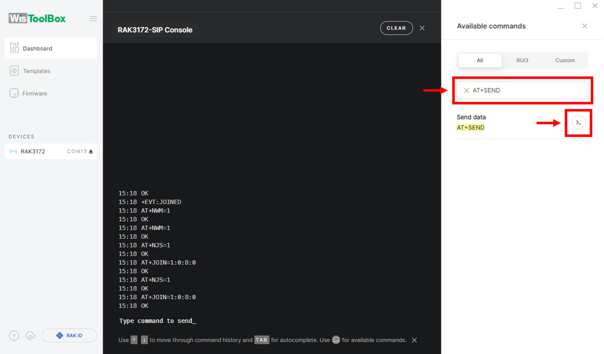 Figure 1: OTAA device sending payload to the network
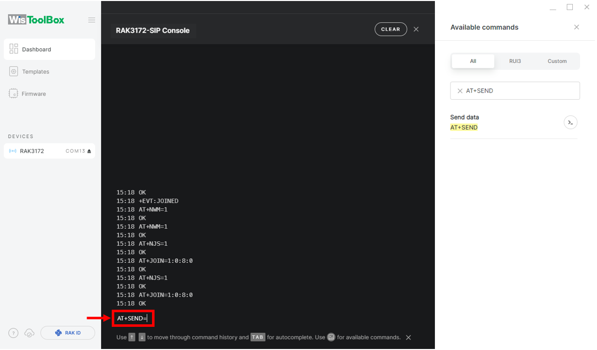 Figure 1: OTAA device sending payload to the network
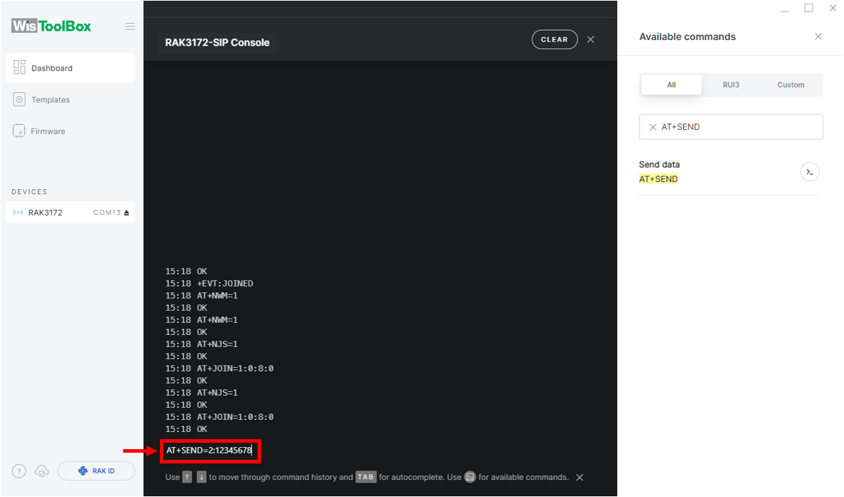 Figure 1: OTAA device sending payload to the network
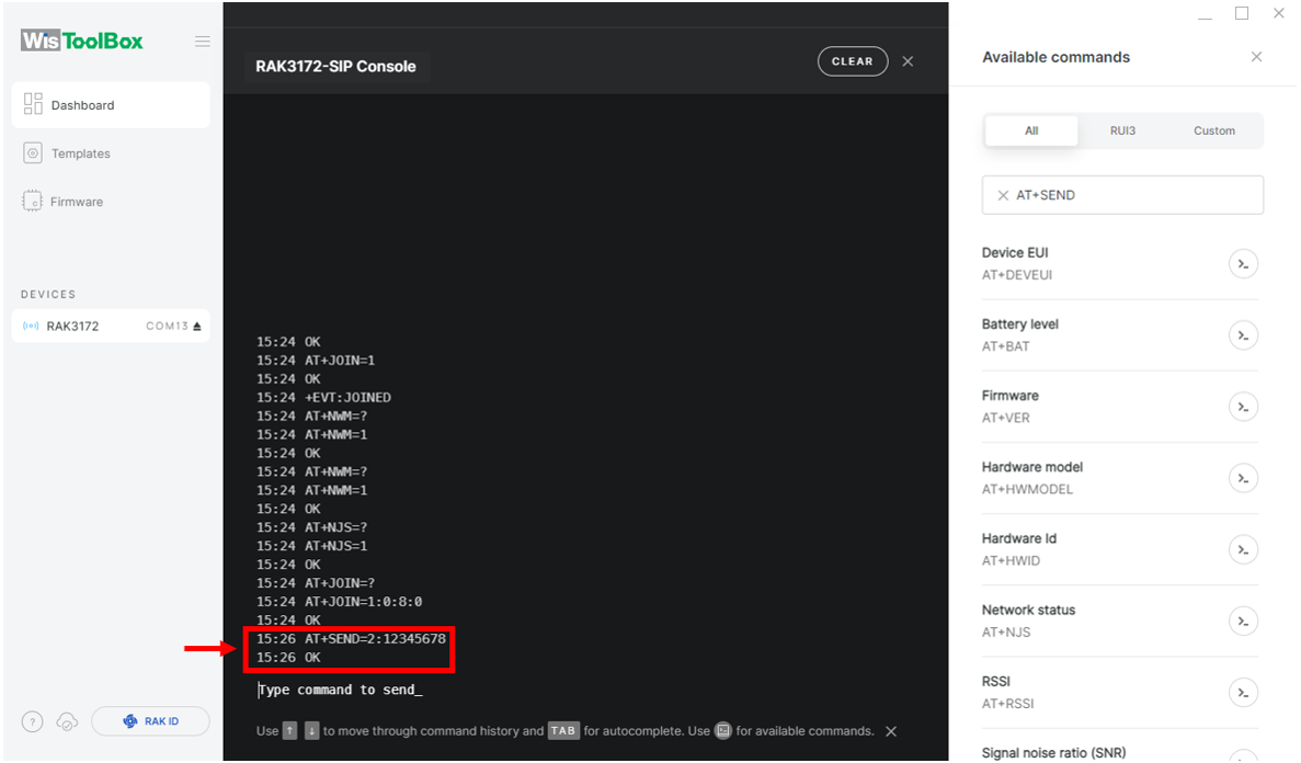 Figure 1: OTAA device sending payload to the network
- You will see the data sent by the RAK3172 module on the TTN device console Live data section. Also, the Last seen info should be a few seconds or minutes ago.
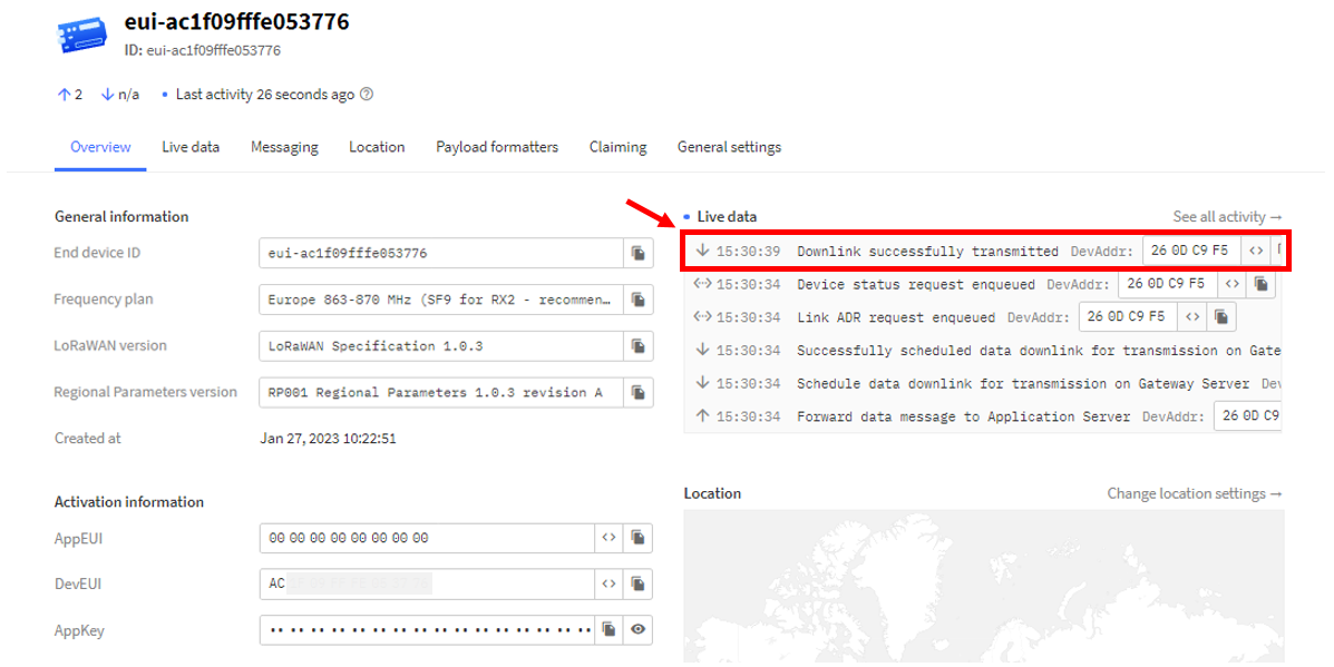 Figure 1: OTAA Test Sample Data Sent Viewed in TTN
TTN ABP Device Registration
- To register an ABP device, navigate to the application console and select the application where the device will be added. Then, click + Register end device, as shown in Figure 121.
 Figure 1: Add ABP Device
- Click the Enter end device specifics manually.
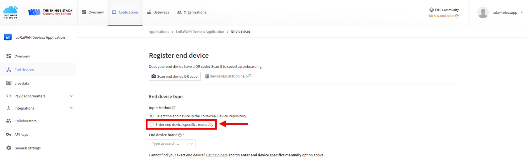 Figure 1: Enter end device specifics manually
- Configure the Frequency Plan, the compatible LoRaWAN Version, and the Regional Parameters Version supported.
 Figure 1: Setup for your device
 Figure 1: Setup for your device
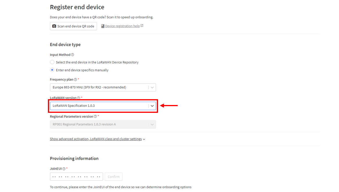 Figure 1: Setup for your device
- Click Show advanced activation, LoRaWAN class and cluster settings.
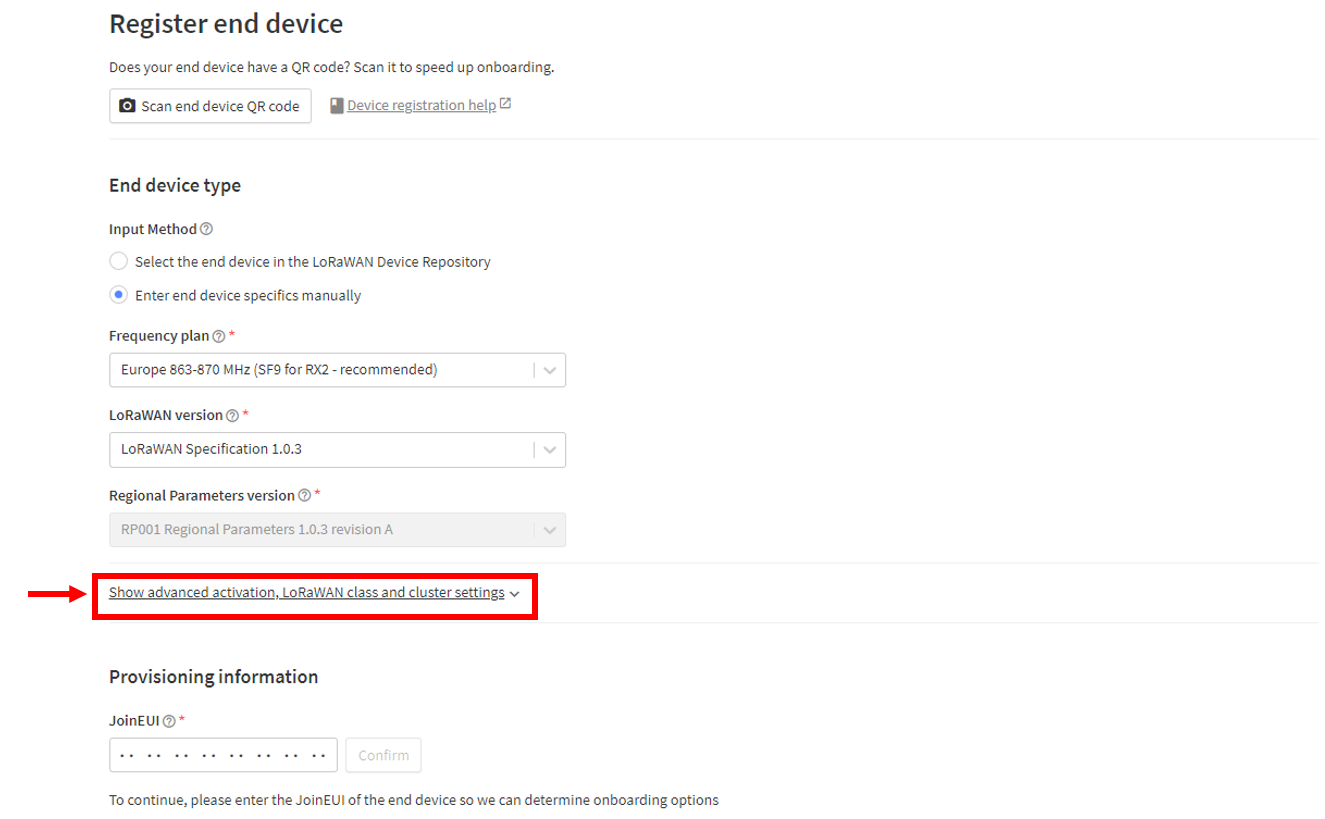 Figure 1: Setup for your device
- Configure the activation mode by selecting Activation by personalization (ABP) and Additional LoRaWAN class capabilities to class A only.
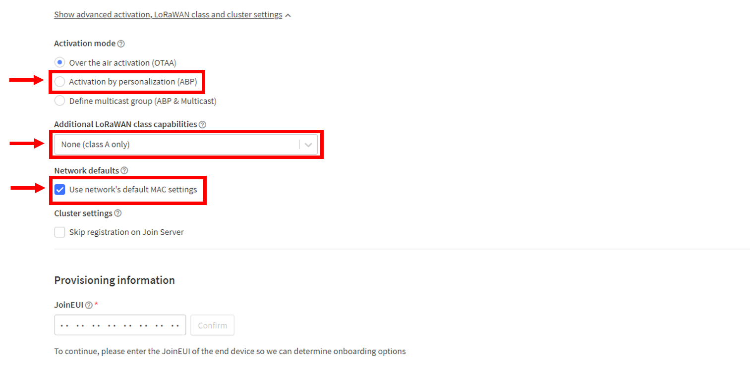 Figure 1: Setup for your device
- Provide the DevEUI credentials of your device into the DevEUI portion. This will automatically generate the specific End device ID of your board.
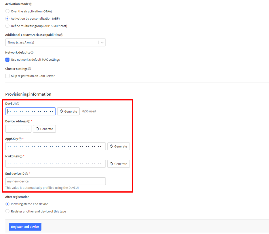 Figure 1: Setup for your device
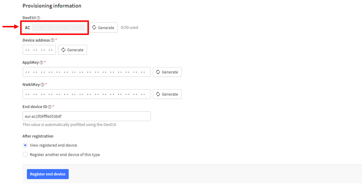 Figure 1: Setup for your device
- Click Generate under Device Address, AppSKey, and NwkSKey in the Provisioning Information section.
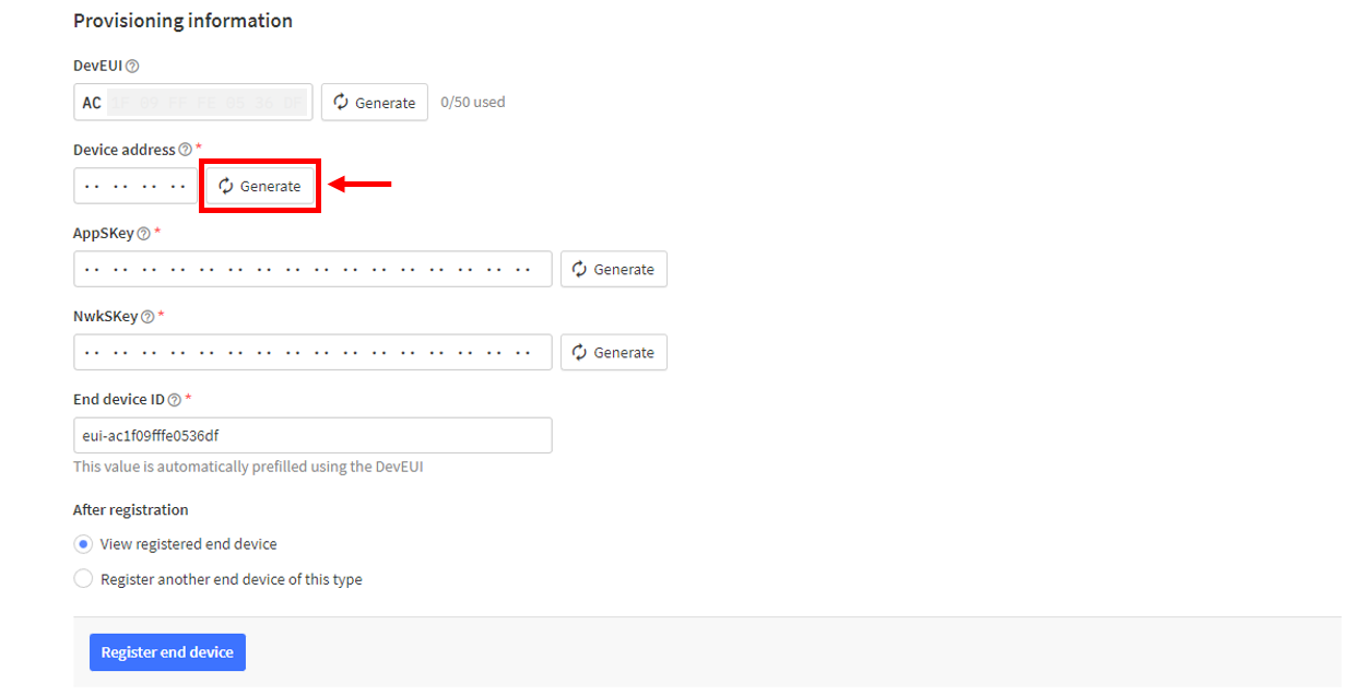 Figure 1: Setup for your device
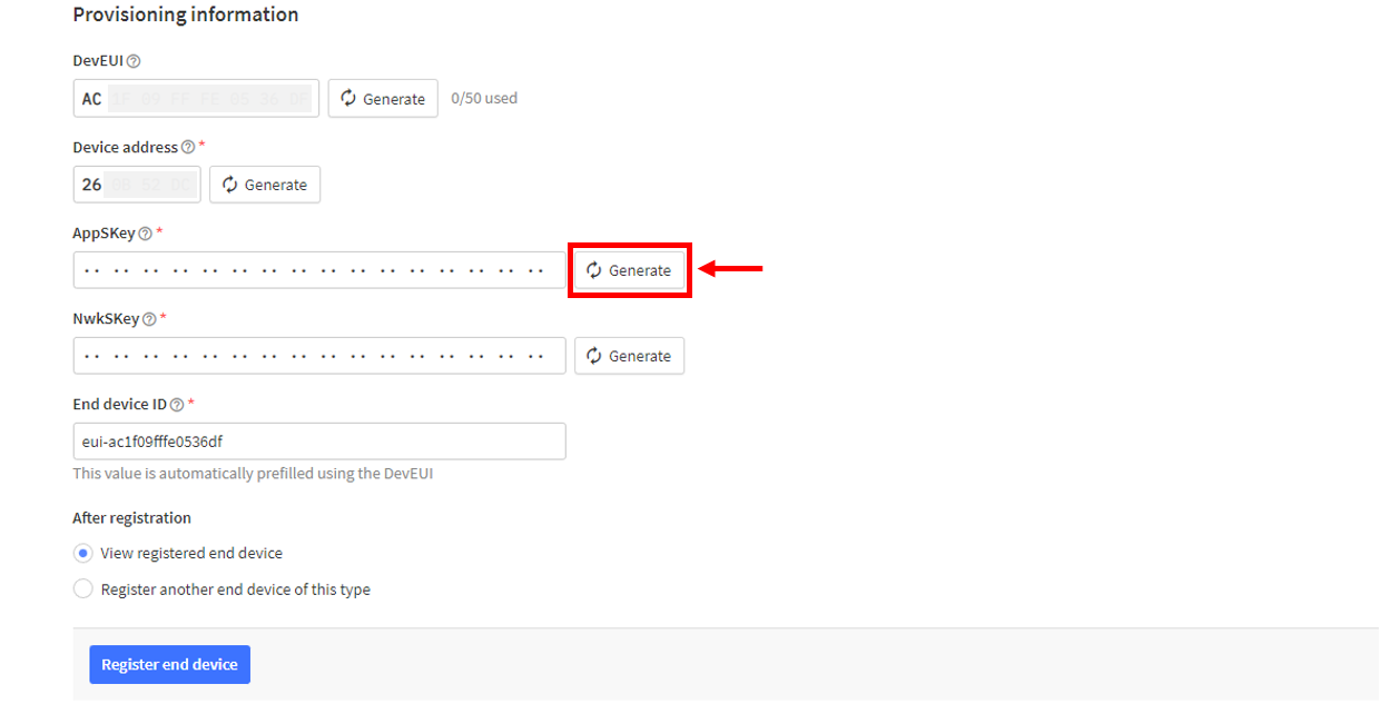 Figure 1: Setup for your device
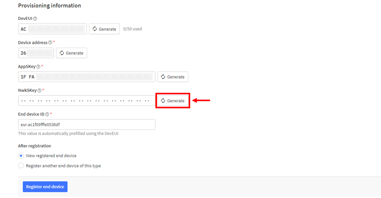 Figure 1: Setup for your device
- Click Register End Device.
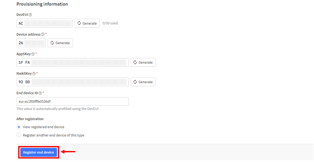 Figure 1: Register end device
- The DevEUI, Device Address, AppSKey, and NwkSKey are hidden in this section as they are unique to each device. Additionally, you must generate your own Device Address, AppSKey, and NwkSKey credentials for your specific device and application.
- You should now be able to see the device on the TTN console, as shown in Figure 134.
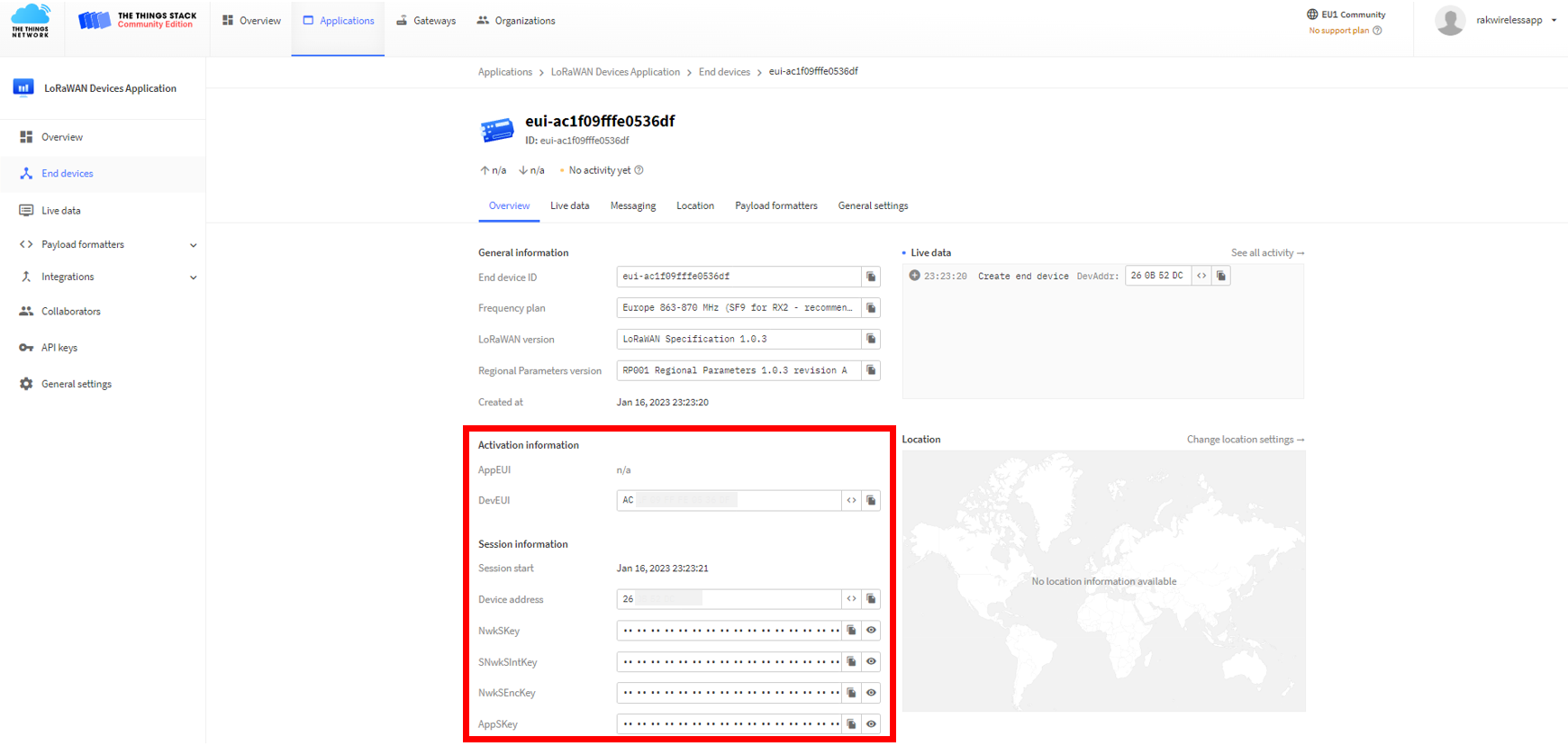 Figure 1: ABP device successfully registered to TTN
ABP Configuration for TTN
The RAK3272-SiP Breakout Board, which includes a RAK3172-SiP module, can be configured for ABP using WisToolBox. This software tool supports the RAK3172 module and automatically detects the module when connected to a PC. Below are the options available in WisToolBox for ABP configuration:
ABP Configuration for TTN via WisToolBox UI
-
Connect the RAK3272-SiP Breakout Board to the PC using the RAKDAP as shown in Figure 27, and open the WisToolBox application.
-
Click CONNECT DEVICE button to launch the WisToolBox Dashboard.
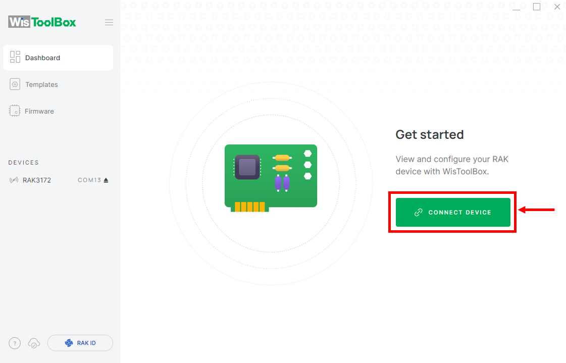 Figure 1: CONNECT DEVICE
- Then select your target port where your RAK3172-SiP is connected. Once recognized, click CONNECT as shown in Figure 137.
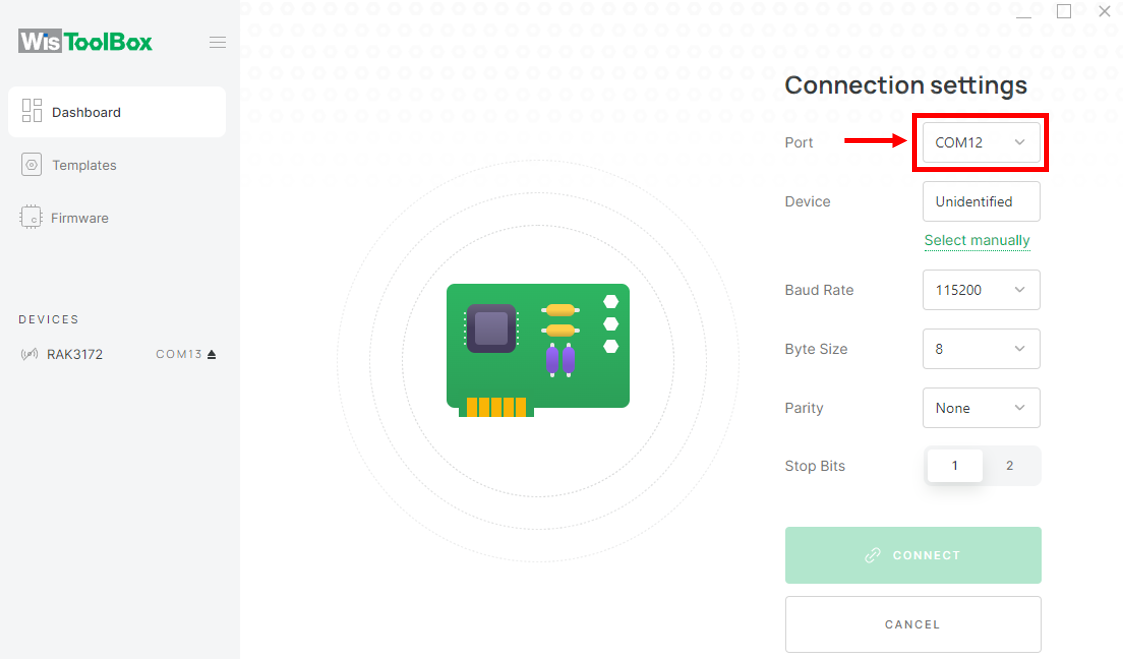 Figure 1: Set up your device
 Figure 1: Set up your device
- The RAK3172-SiP will appear on the dashboard; select it to proceed.
 Figure 1: Device seen from WisToolBox dashboard
- Click PARAMETERS.
The AppSKey, Device address, and NwkSKey are hidden in this section as these are unique from a specific device.
 Figure 1: Set up your device
- Click Global settings.
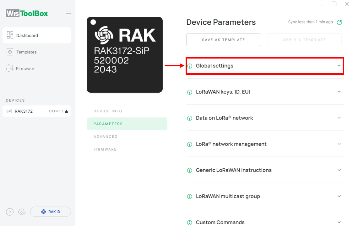 Figure 1: Global settings
- Set the network mode to LoRaWAN and the join mode to ABP. Then, select the active region based on your location.
- LoRa network mode: LoRaWAN
- LoRaWAN join mode: ABP
- LoRaWAN region: EU868
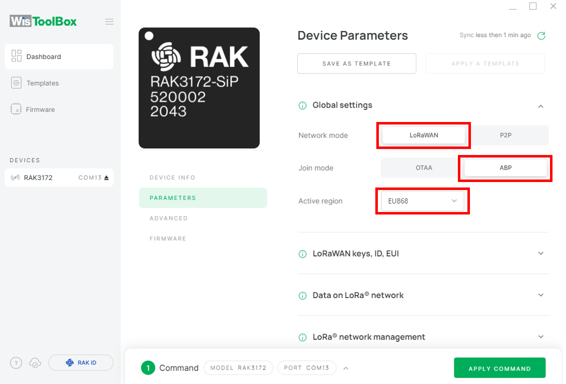 Figure 1: Global settings
- Click LoRaWAN keys, ID, EUI.
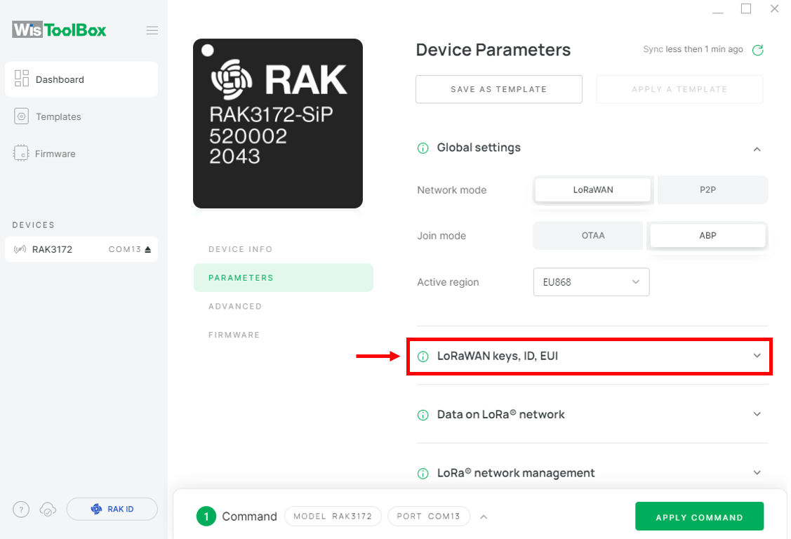 Figure 1: LoRaWAN keys, ID, EUI
- Configure the Application session key (AppSKey), Device address and Network session key (NwkSKey).
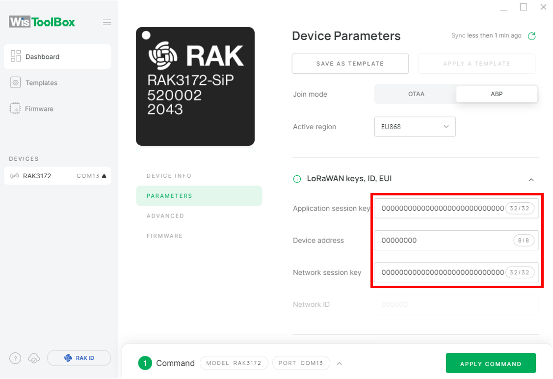 Figure 1: Set up your device
- Return to the TTN console where your RAK3172 end device was previously created and copy all the credentials. These credentials will also be used in the WisToolBox dashboard. Once entered into the dashboard, click APPLY COMMANDS to update your device, as shown in Figure 151.
- The AppSKey, Device address, and NwkSKey are hidden in this section as these are unique from a specific device.
 Figure 1: Your created ABP device from your console
- For Application session key (AppSKey)
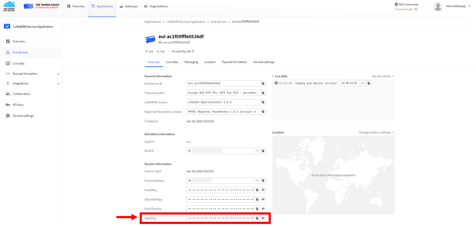 Figure 1: Copy the AppSKey credential from TTN to WisToolBox
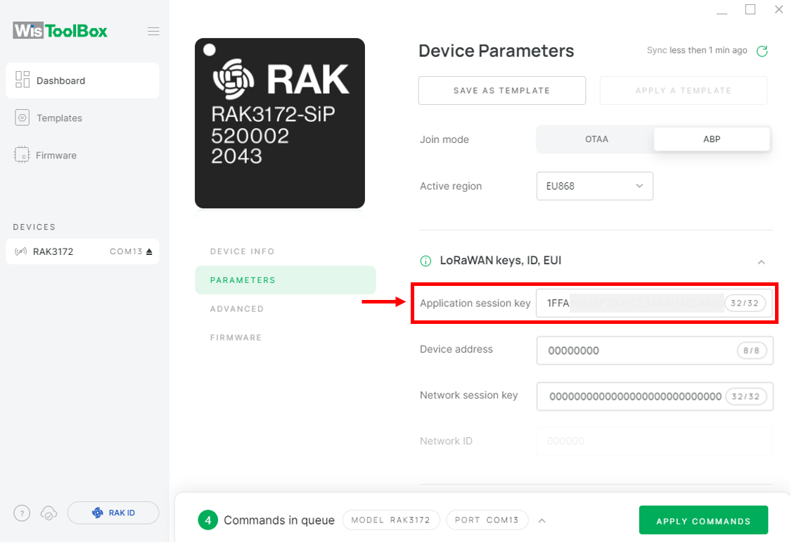 Figure 1: Copy the AppSKey credential from TTN to WisToolBox
- For Device address
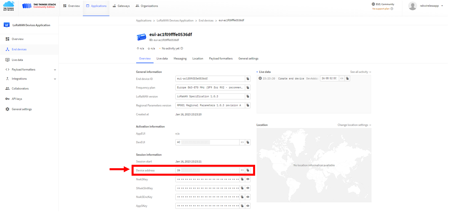 Figure 1: Copy the Device address credential from TTN to WisToolBox
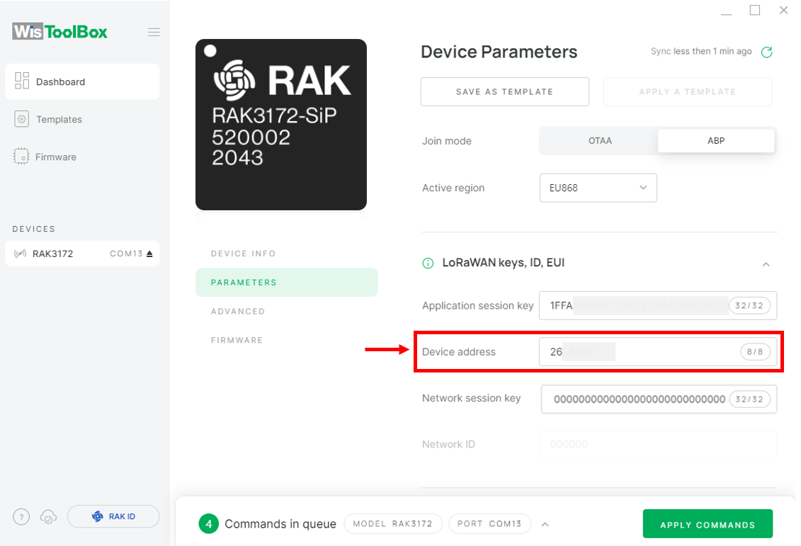 Figure 1: Copy the Device address credential from TTN to WisToolBox
- For Network session key (NwkSKey)
 Figure 1: Copy the NwkSKey credential from TTN to WisToolBox
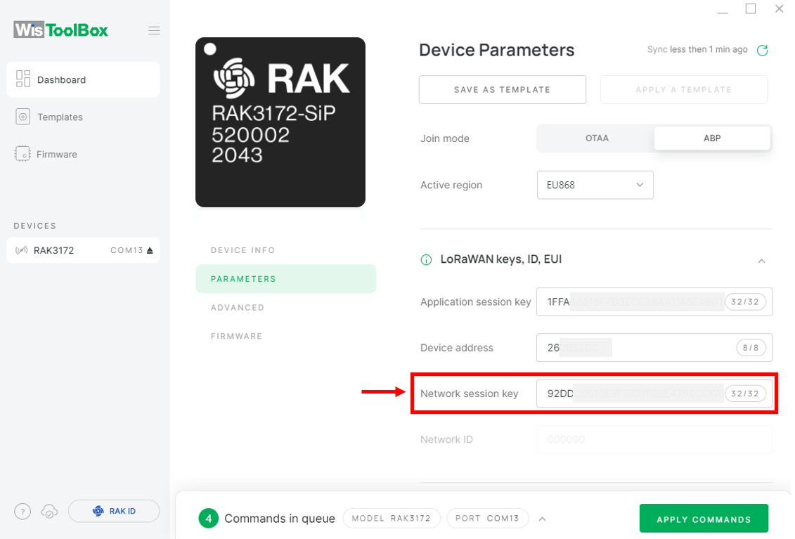 Figure 1: Copy the NwkSKey credential from TTN to WisToolBox
- WisToolBox Dashboard
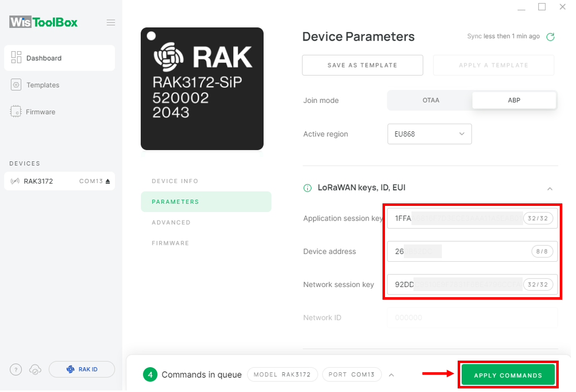 Figure 1: Used credentials from your console in WisToolBox dashboard
- Once completed, a summary of the commands applied to your device will be displayed. Then, click CLOSE.
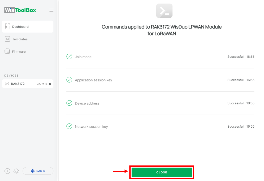 Figure 1: Summary of commands
You will be redirected back to the dashboard, where the updated credentials of your device will be displayed.
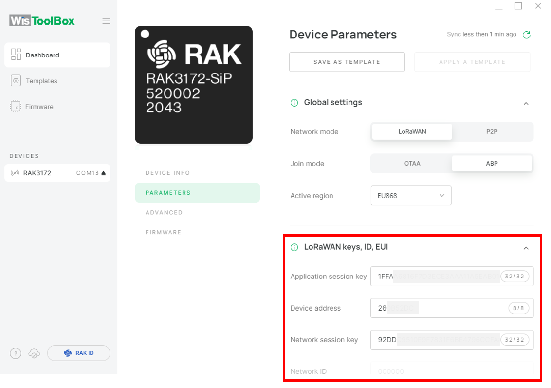 Figure 1: Successfully configured ABP device via WisToolBox dashboard
ABP Configuration for TTN via WisToolBox Console
-
Connect the RAK3172 Breakout Board to the PC using the RAKDAP as shown in Figure 27, and open the WisToolBox application.
-
Click CONNECT DEVICE button to launch the WisToolBox Dashboard.
 Figure 1: CONNECT DEVICE
- Then select your target port where your RAK3172-SiP is connected. Once recognized, click CONNECT.
 Figure 1: Set up your device
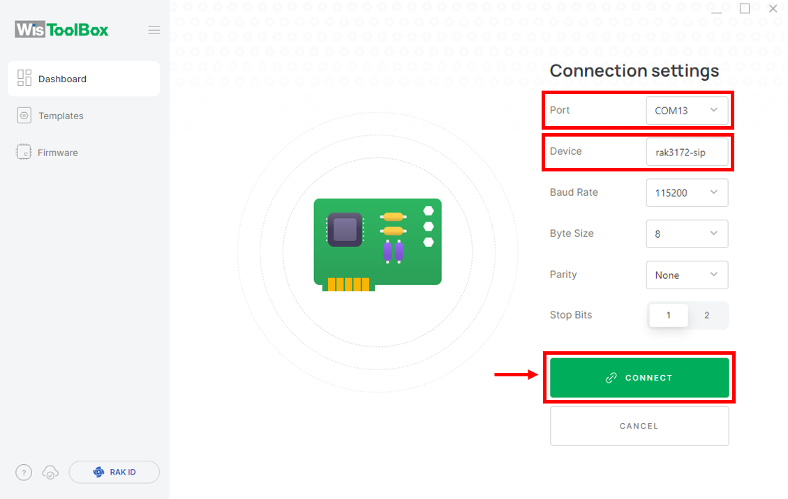 Figure 1: Set up your device
- The RAK3172 will appear on the dashboard; select it to proceed.
 Figure 1: Device seen from WisToolBox dashboard
- Click ADVANCED.
 Figure 1: Set up your device
- Click OPEN CONSOLE.
 Figure 1: OPEN CONSOLE
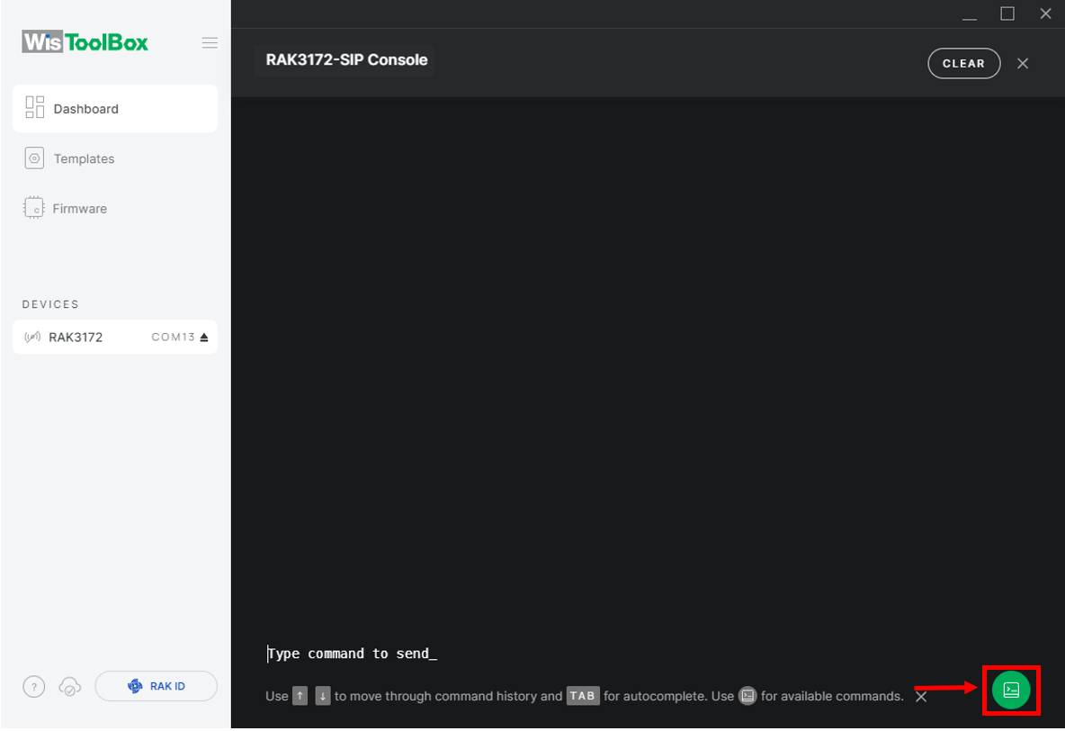 Figure 1: Open the Console terminal of WisToolBox
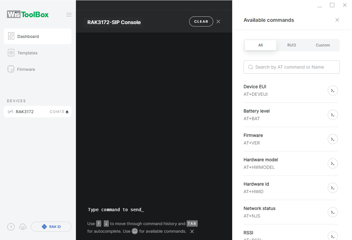 Figure 1: Open the Console terminal of WisToolBox
- To begin the configuration, type
ATEto enable command echoing during the setup process. Then press Enter.
It is recommended to start by testing the console and verify that the current configuration is working by sending these two AT commands:
AT
ATE
ATE is useful for tracking the commands and troubleshooting.
You will receive OK after entering the two commands. Once ATE is set, all the commands you input, along with their replies, will be displayed.
If you do not receive an OK or any reply, verify that the device is powered correctly. If using a USB port for power, ensure you are using a reliable USB cable.
 Figure 1: Set up your Console
 Figure 1: Set up your Console
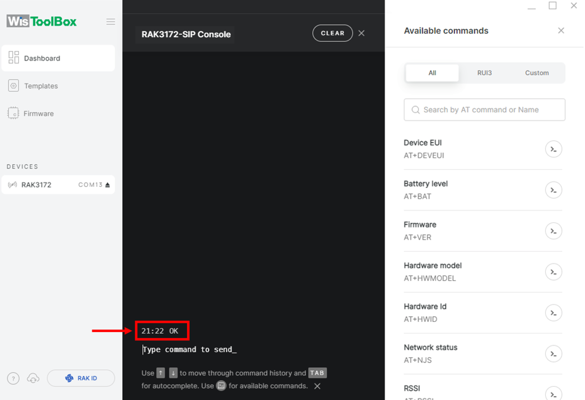 Figure 1: Set up your Console
- Configure the LoRaWAN join mode to ABP. Check the current parameter by typing AT+NJM? and pressing Enter in the console terminal.
 Figure 1: Set up your Console
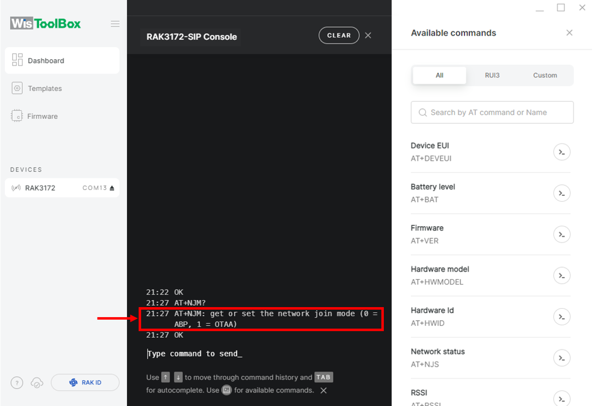 Figure 1: Set up your Console
- For ABP, input AT+NJM=0 and press Enter.
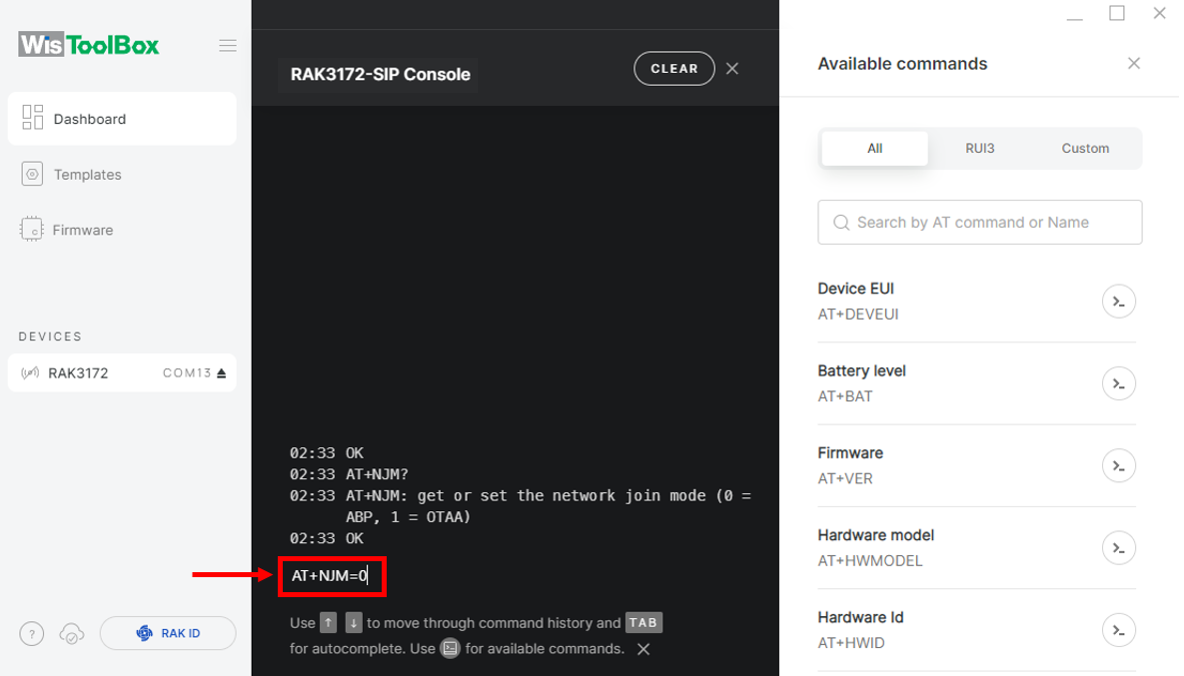 Figure 1: Set up your Console
- Set up your LoRaWAN region. Check the available parameters by typing AT+BAND? and pressing Enter in the console terminal.
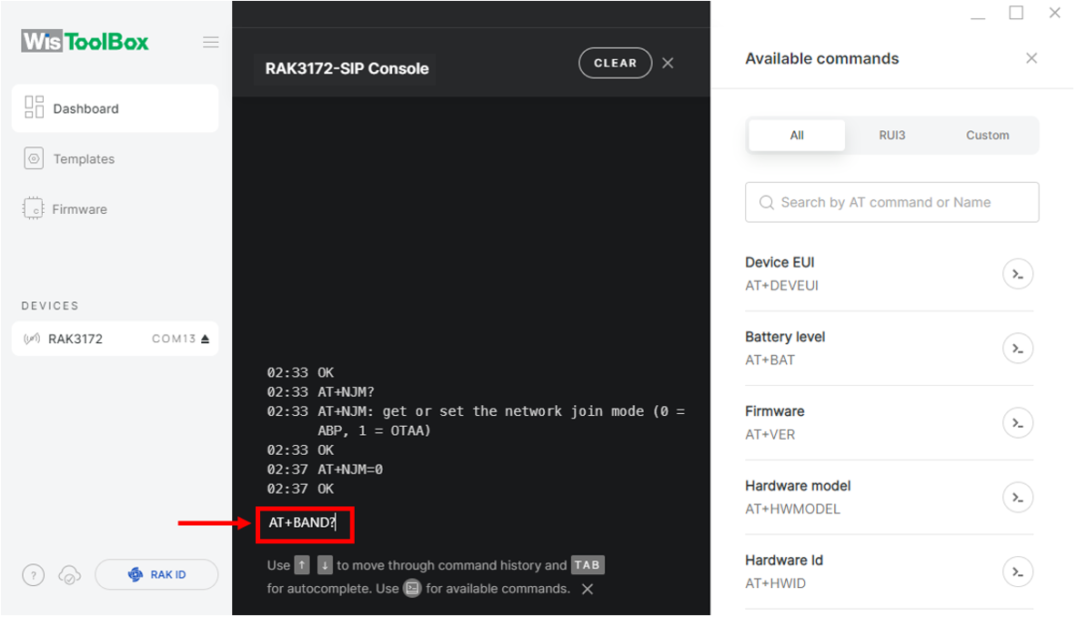 Figure 1: Set up your Console
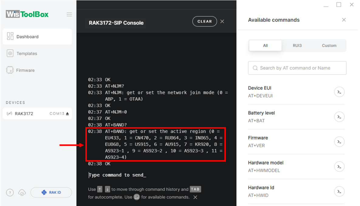 Figure 1: Set up your Console
- For EU868, input AT+BAND=4 and press Enter. If you need to configure a different regional band, refer to the list of available band parameter options.
AT+BAND=4
-
Depending on the regional band selected, you may need to configure the sub-band of your RAK3172 to match the gateway and LoRaWAN network server. This step is especially critical for regional bands like US915, AU915, and CN470.
-
To configure the channel masking for the sub-bands, use the
AT+MASKcommand, as detailed in the AT Command Manual. -
For example, to use sub-band 2, send the command:
AT+MASK=0002.
List of band parameter options
| Code | Regional Band |
|---|---|
| 0 | EU433 |
| 1 | CN470 |
| 2 | RU864 |
| 3 | IN865 |
| 4 | EU868 |
| 5 | US915 |
| 6 | AU915 |
| 7 | KR920 |
| 8 | AS923-1 |
| 9 | AS923-2 |
| 10 | AS923-3 |
| 11 | AS923-4 |
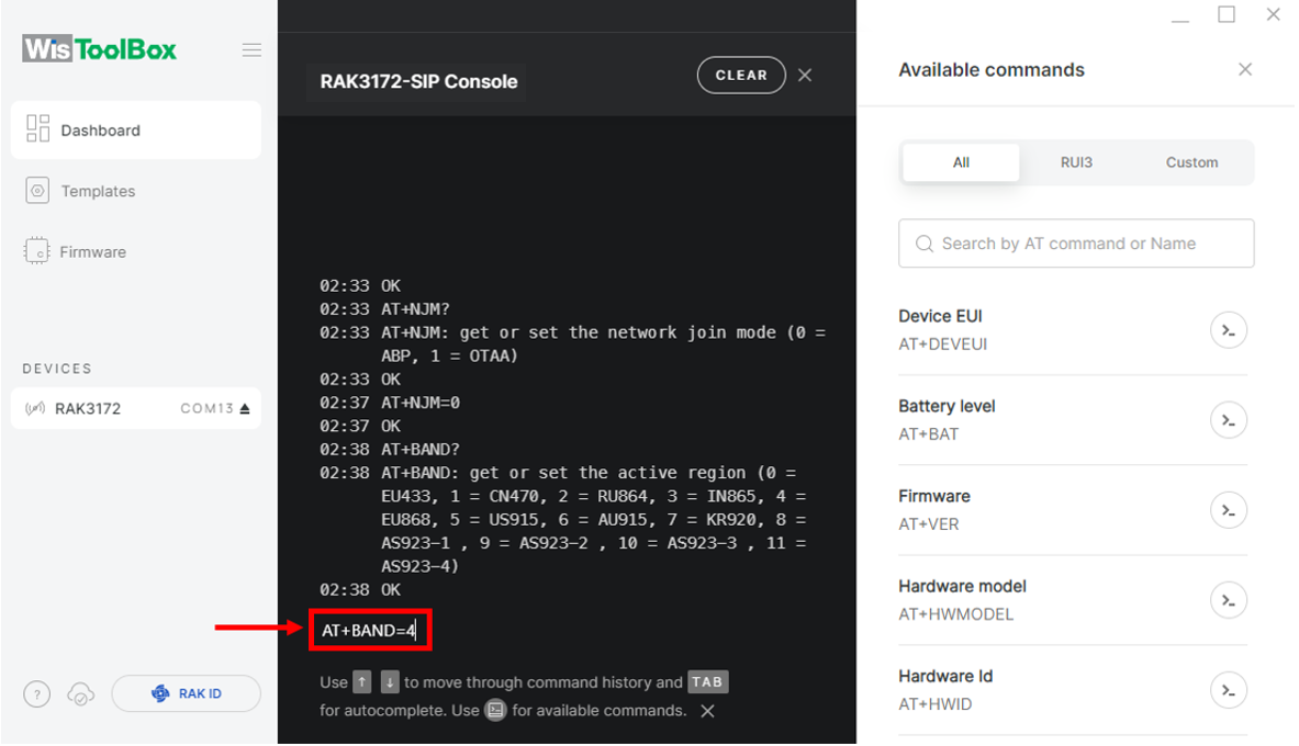 Figure 1: Set up your Console
- Return to the TTN console where the RAK3172 was created, copy the AppSKey credential, paste it into the WisToolBox console, and press Enter.
 Figure 1: Your created ABP device from your TTN console
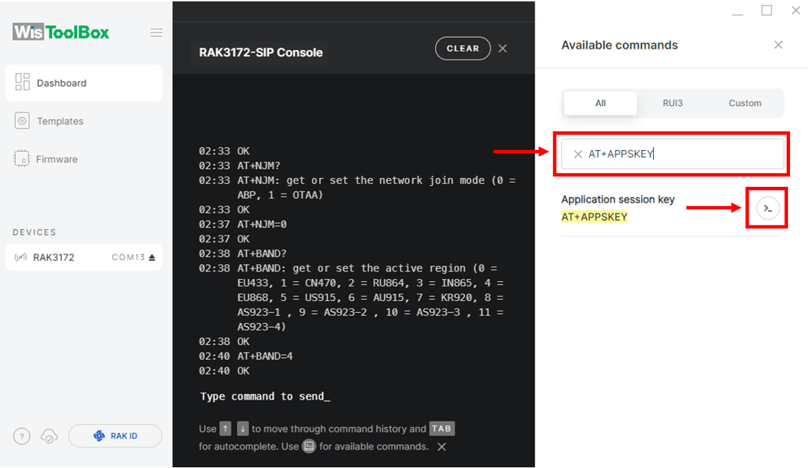 Figure 1: Set up your Console
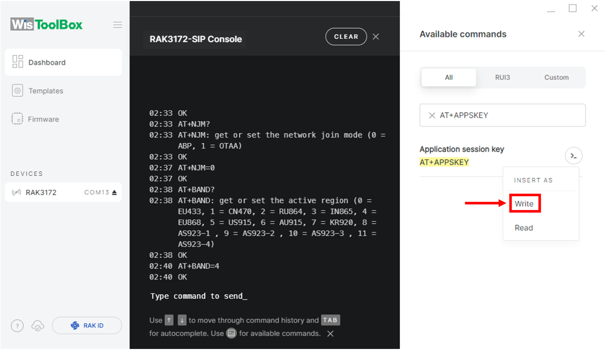 Figure 1: Set up your Console
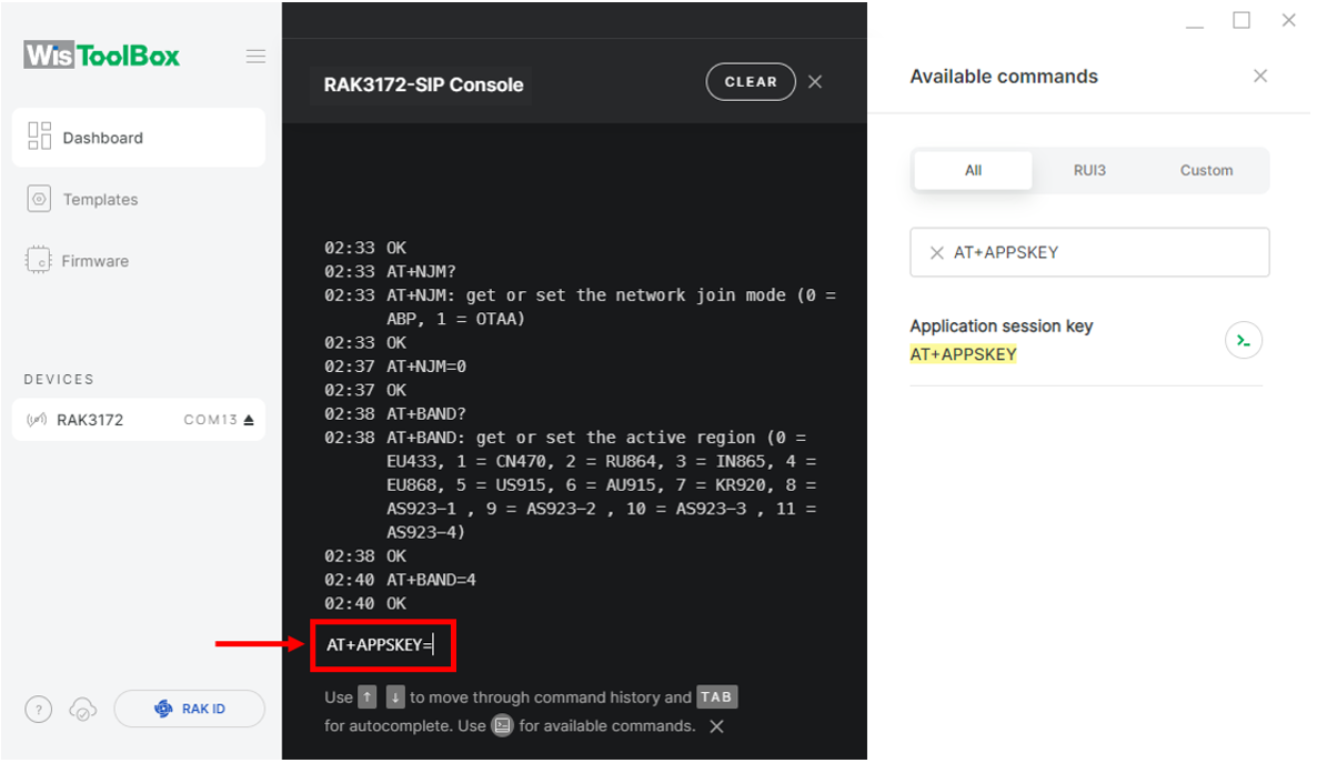 Figure 1: Set up your Console
 Figure 1: Copy the AppSKey credential from TTN to WisToolBox
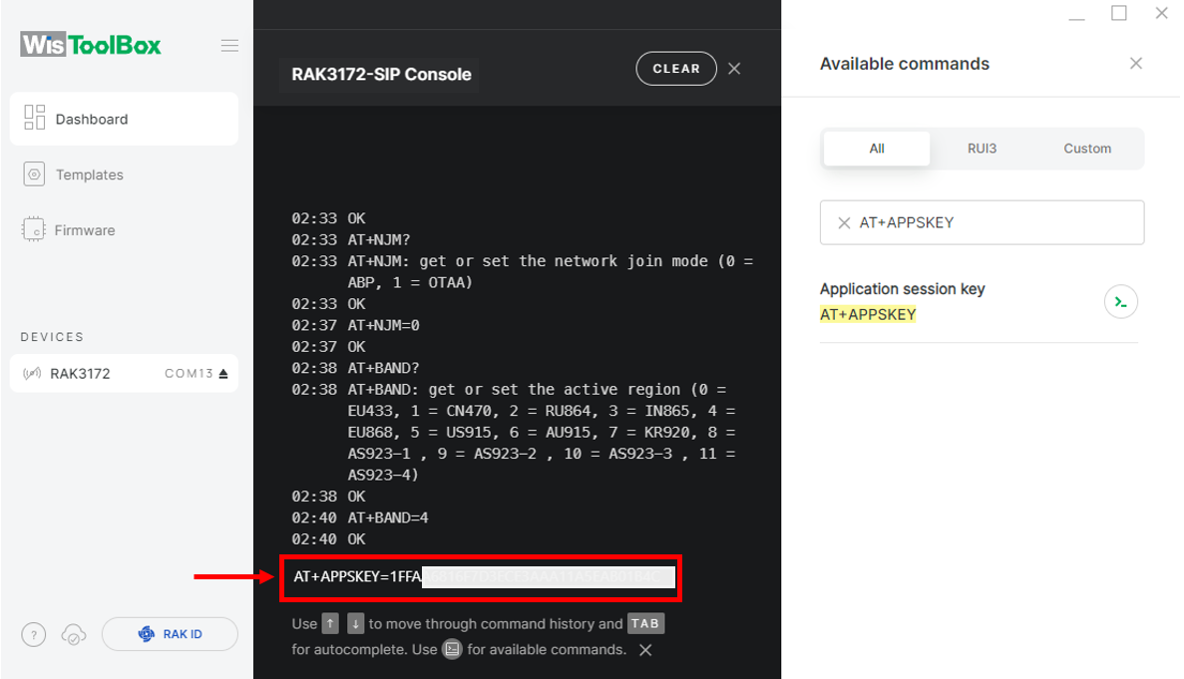 Figure 1: Set up your Console
- Repeat the procedure for the Device Address and Network Session Key (NwkSKey).
- For Device address
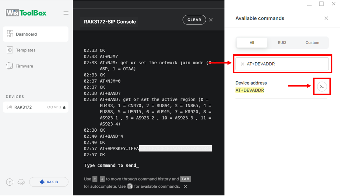 Figure 1: Set up your Console
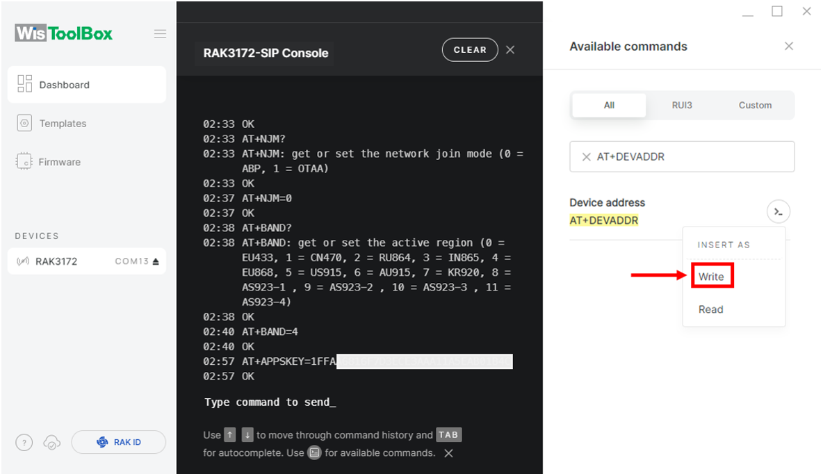 Figure 1: Set up your Console
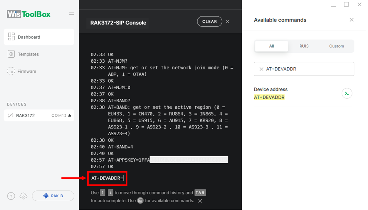 Figure 1: Set up your Console
 Figure 1: Copy the Device address credential from TTN to WisToolBox
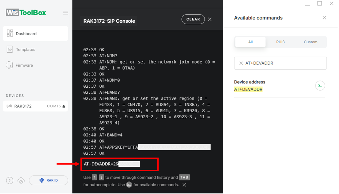 Figure 1: Set up your Console
- For Network session key (NwkSKey)
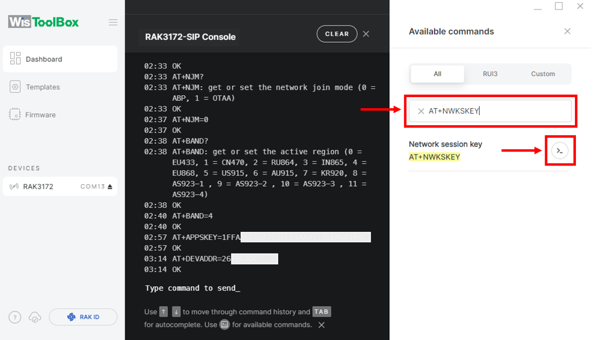 Figure 1: Set up your Console
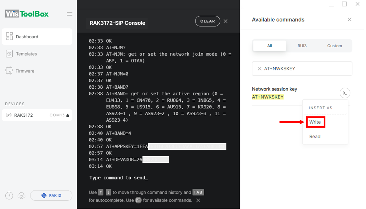 Figure 1: Set up your Console
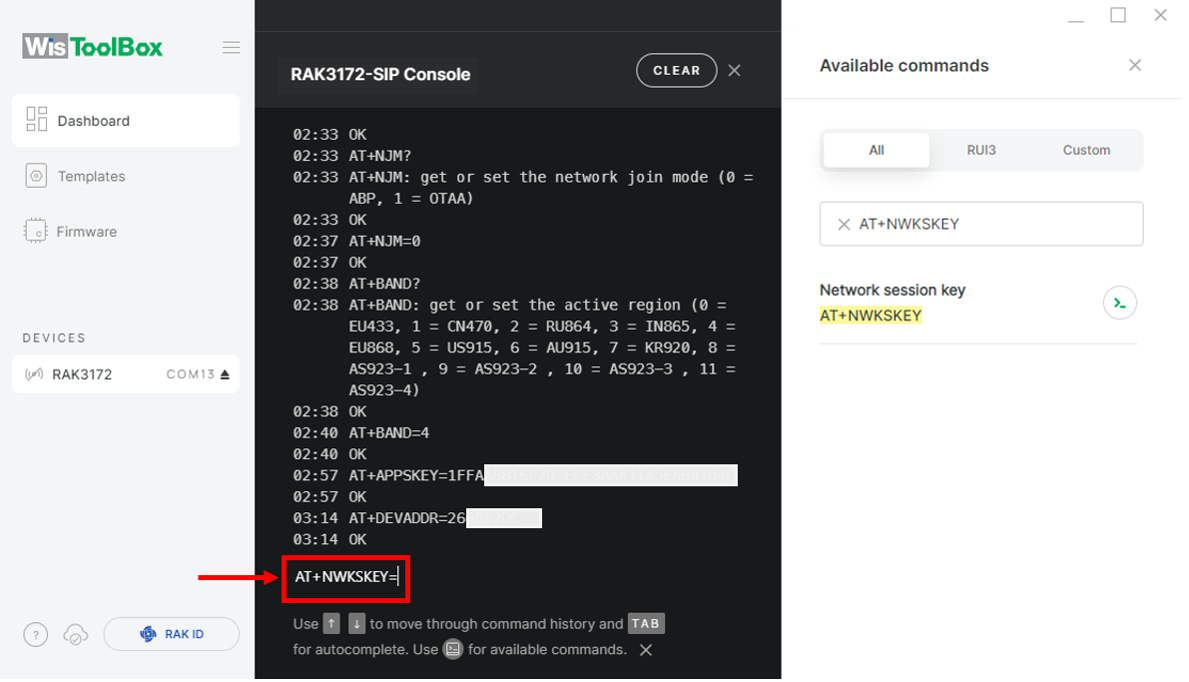 Figure 1: Set up your Console
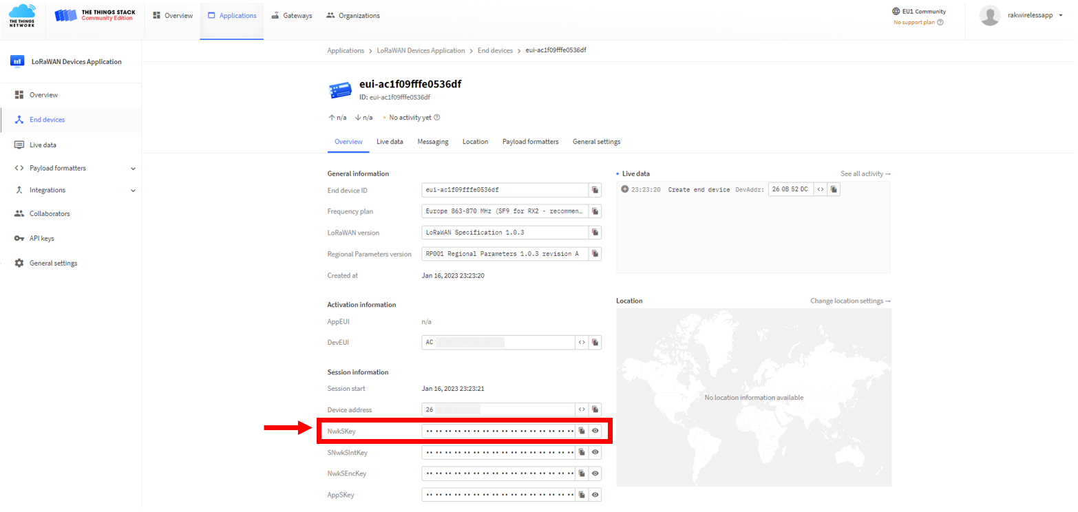 Figure 1: Copy the NwkSKey credential from TTN to WisToolBox
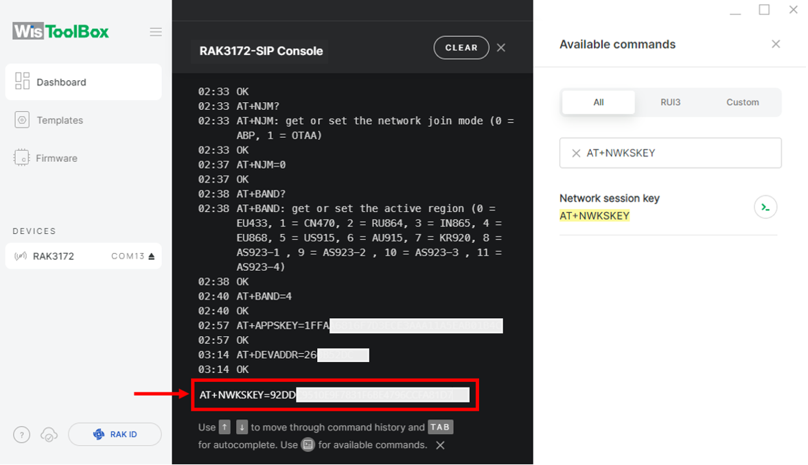 Figure 1: Set up your Console
- Once completed, click Dashboard to verify the updated credentials of your ABP device.
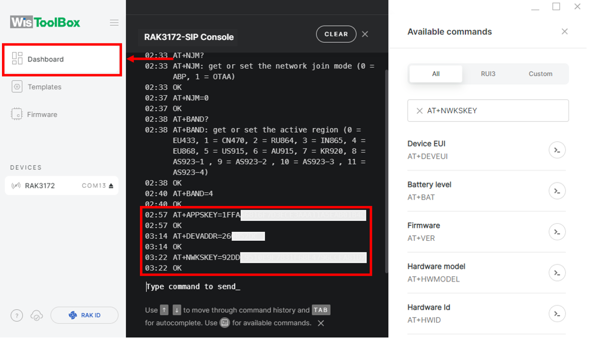 Figure 1: Set up your Console
 Figure 1: Set up your Console
- Click PARAMETERS.
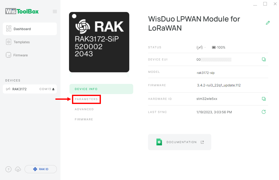 Figure 1: PARAMETERS
- Open the Global Settings.
 Figure 1: Global settings and LoRaWAN keys, ID, EUI
- Verify that the LoRaWAN Keys, ID, EUI fields have been updated.
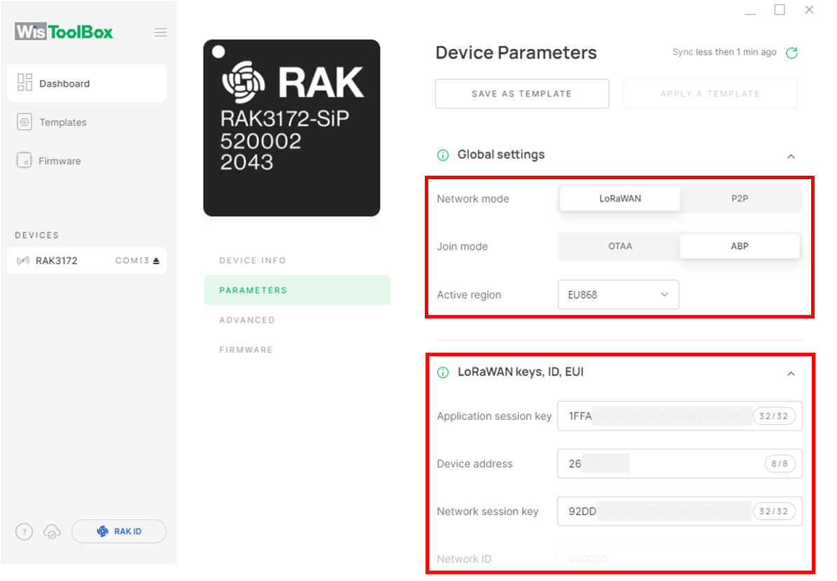 Figure 1: Global settings and LoRaWAN keys, ID, EUI details
You now have a configured ABP device using the WisToolBox console. ABP-configured devices are directly connected to the network once the above procedures are completed, so no joining procedure is required.
- To send a payload to TTN, reopen the terminal console in WisToolBox. Use the following command format:
AT+SEND=<port>:<payload>.
AT+SEND=2:12345678
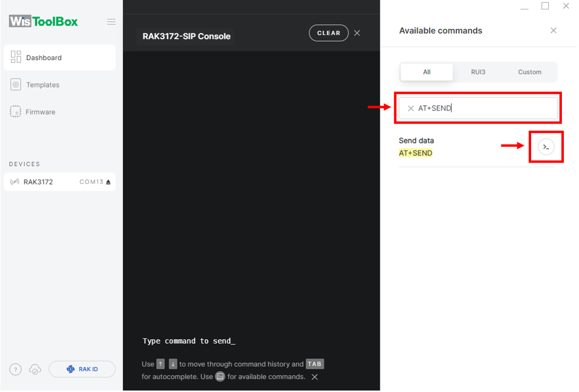 Figure 1: ABP device sending payload to the network
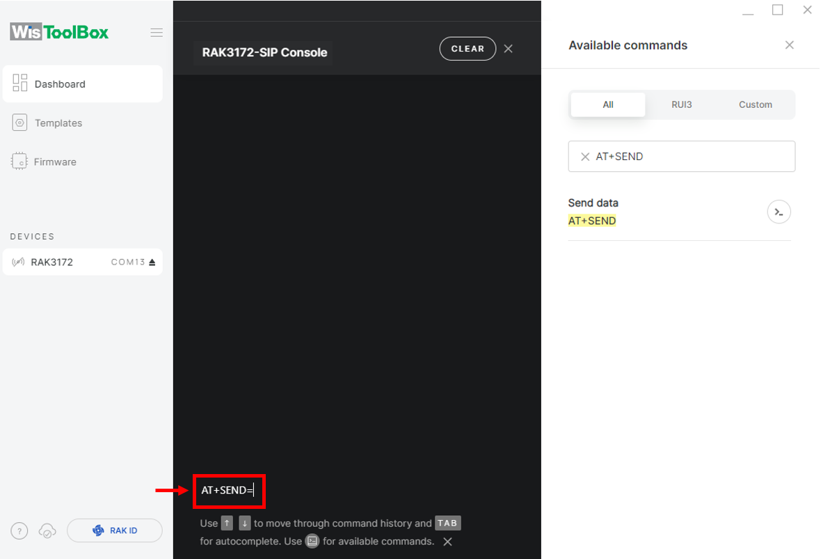 Figure 1: ABP device sending payload to the network
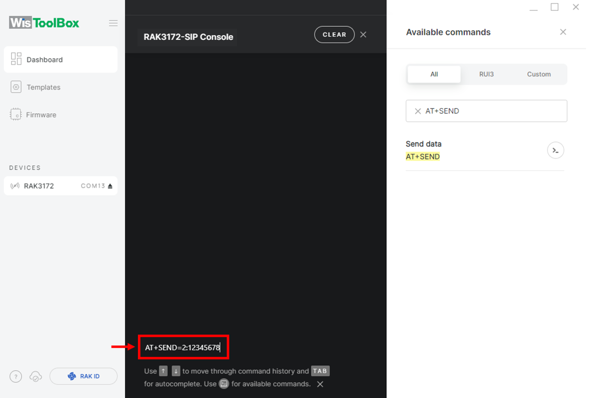 Figure 1: ABP device sending payload to the network
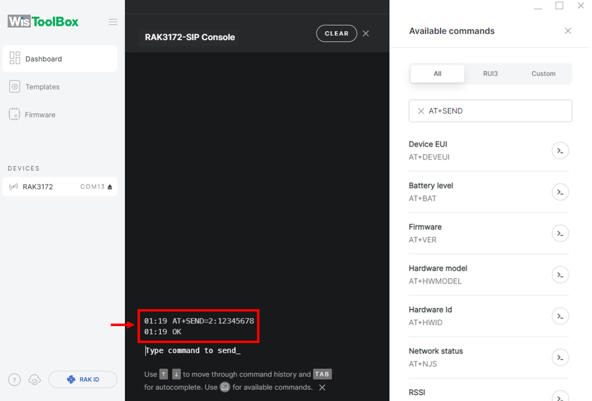 Figure 1: ABP device sending payload to the network
- You will see the data sent by the RAK3172 module on the TTN device console Live data section. Also, the Last seen info should be a few seconds or minutes ago.
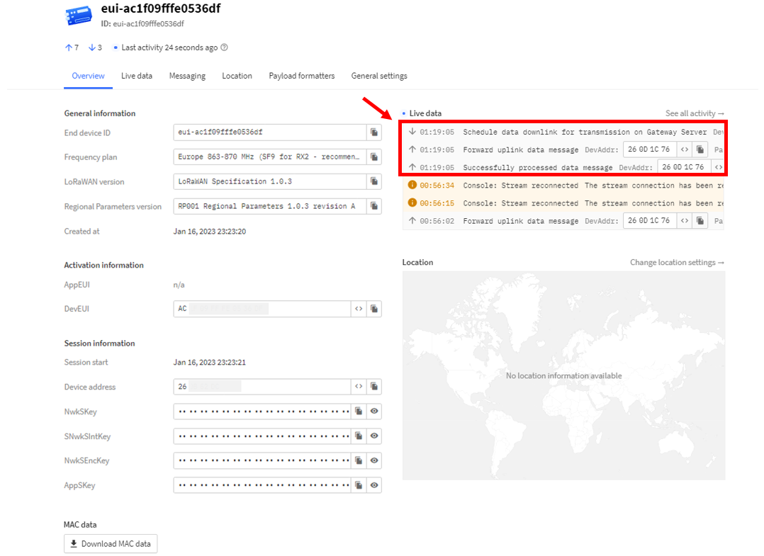 Figure 1: ABP Test Sample Data Sent Viewed in TTN
Connect with ChirpStack
This section shows how to connect the RAK3272-SiP Breakout Board to the ChirpStack platform.
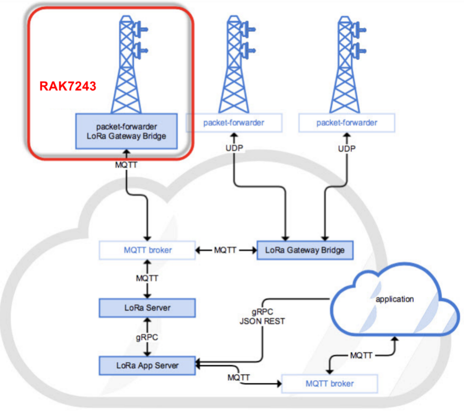 Figure 1: RAK3272-SiP Module in the context of the ChirpStack platform
The ChirpStack or previously known as the LoRaServer project provides open-source components for building LoRaWAN networks. Like the case of TTN, the RAK3272-SiP Breakout Board is located in the periphery and will transmit the data to the backend servers through a LoRaWAN gateway. Learn more about ChirpStack.
It is assumed that you are using RAK Gateway and its built-in ChirpStack. Also, the gateway with the ChirpStack must be configured successfully. For further information, check the RAK documents.
-
In summary, these are the requirements:
- Have a ChirpStack online gateway, the frequency band of the nodes should be consistent with the frequency band of the gateway in use.
- RAK Serial Port Tool provided by RAK
- RAK3272-SiP Breakout Board
The frequency band used in the demonstration is EU868.
Create a New Application
-
Log in to the ChirpStack server using your account and password.
-
Go to the Application section.
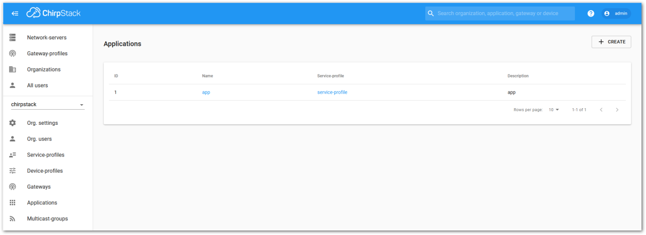 Figure 1: Application section
- Create a new Application by clicking on the CREATE button, and filling the required parameters.
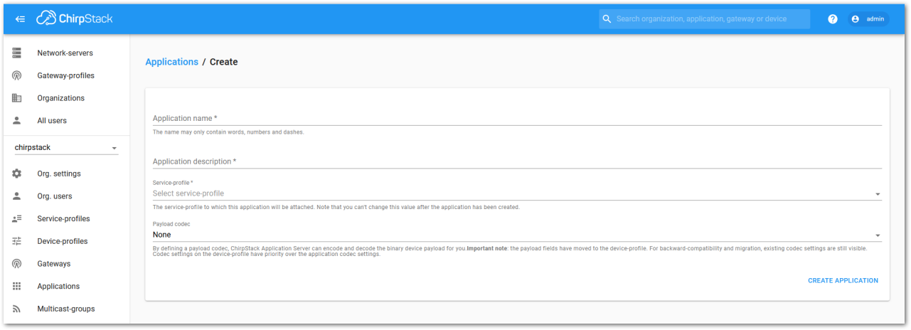 Figure 1: Create a new application
- For this setup, create an Application named rak_node_test.
The ChirpStack LoRaServer supports multiple system configurations, with one configuration set as default:
- Service Profile: Used to select the system profile.
- Payload Codec: Defines the parsing method for load data, such as parsing LPP format data.
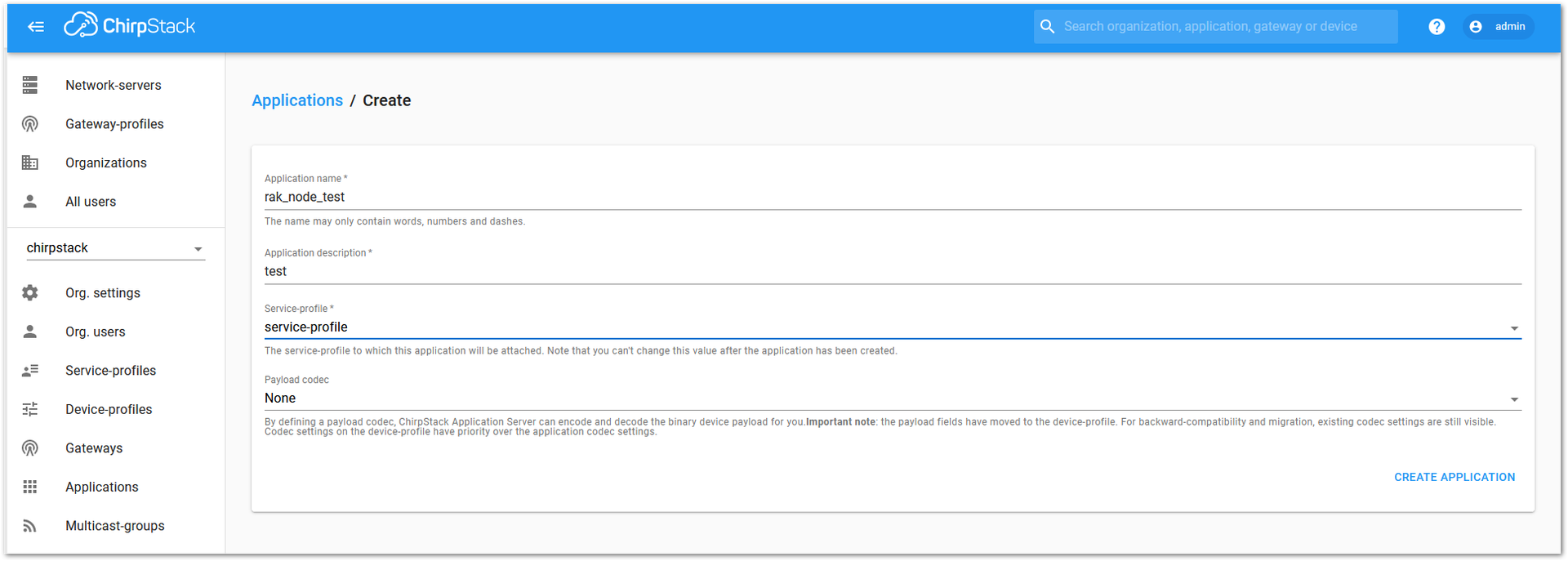 Figure 1: Fill in in the parameters of an application
- Choose the Application created in the previous step, then select the DEVICES tab.
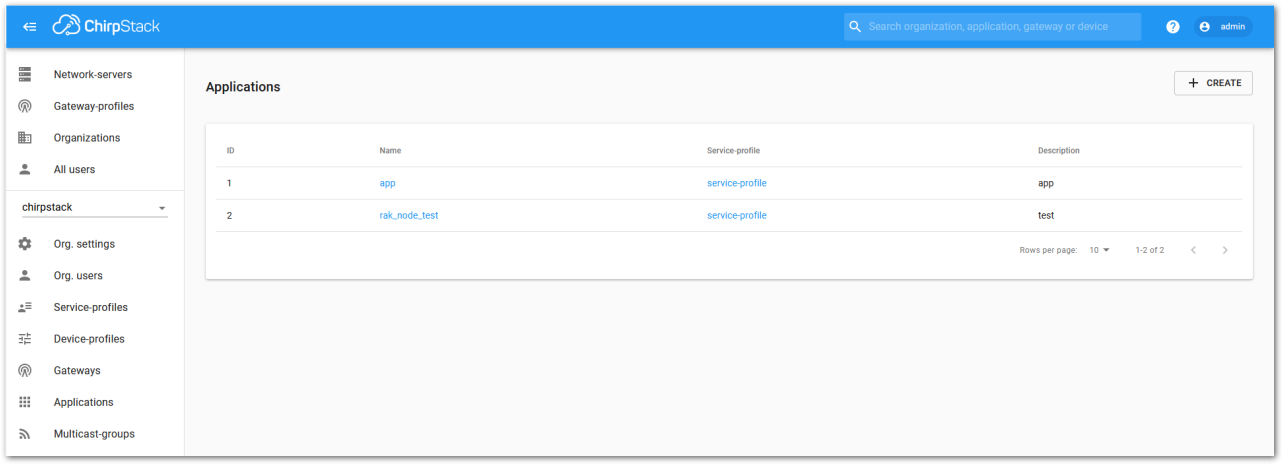 Figure 1: List of applications created
- Once done, click “+ CREATE”.
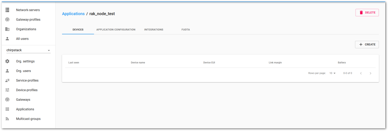 Figure 1: Device tab of an application
- Within the DEVICE tab, create a new device (LoRaWAN node) by clicking the + CREATE button.
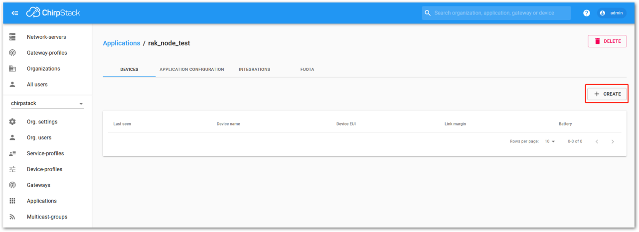 Figure 1: Add a new device
 Figure 1: Chirpstack Adding Node into the RAK3272-SiP Breakout
- After creating the node, fill in the required information. You can either generate a Device EUI automatically by clicking the icon or manually enter a valid Device EUI in the edit box.
Fill in the parameters requested:
-
Device name and Device description: These are descriptive texts about your device.
-
Device EUI: This interface allows you to generate a Device EUI automatically by clicking the generate icon. You can also add a specific Device EUI directly in the form.
-
Device Profile:
- If you want to join in OTAA mode, select DeviceProfile_OTAA.
- If you want to join in ABP mode, select DeviceProfile_ABP.
- Device profiles DeviceProfile_OTAA and DeviceProfile_ABP are only available if you are using the built-in Chirpstack LoRaWAN Server of RAK Gateways.
- If you have your own Chirpstack installation, you can set up the device profile with
LoRaWAN MAC version 1.0.4andLoRaWAN Regional Parameters revision Bto make it compatible with RAK3272-SiP.
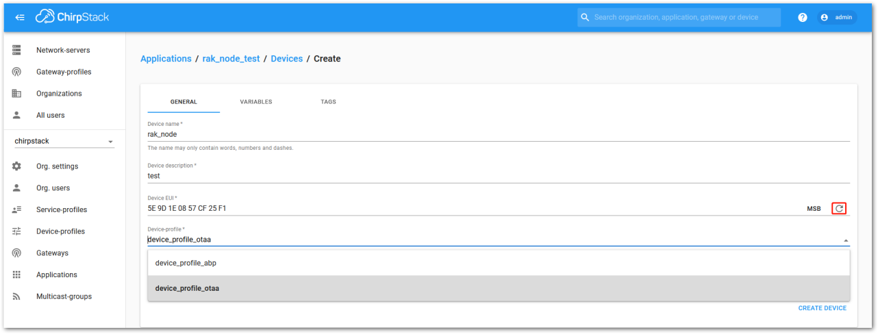 Figure 1: Generate a new device EUI
Chirpstack OTAA Device Registration
- If you have selected DeviceProfile_OTAA, as shown in Figure 206, an Application Key must be created for the device after it is set up.
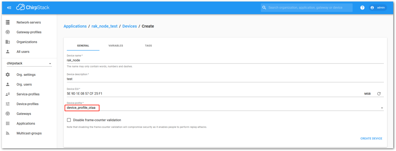 Figure 1: Chirpstack OTAA activation
- You can either enter a previously created Application Key or generate a new one automatically by clicking the icon highlighted in red in Figure 207.
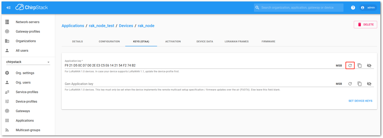 Figure 1: Chirpstack OTAA set application keys
- Once the Application Key is added to the form, the process can be finalized by clicking on the SET DEVICE-KEYS button.
- As shown in Figure 208, a new device should be listed in the DEVICES tab. The most important parameters, such as the Device EUI are shown in the summary.
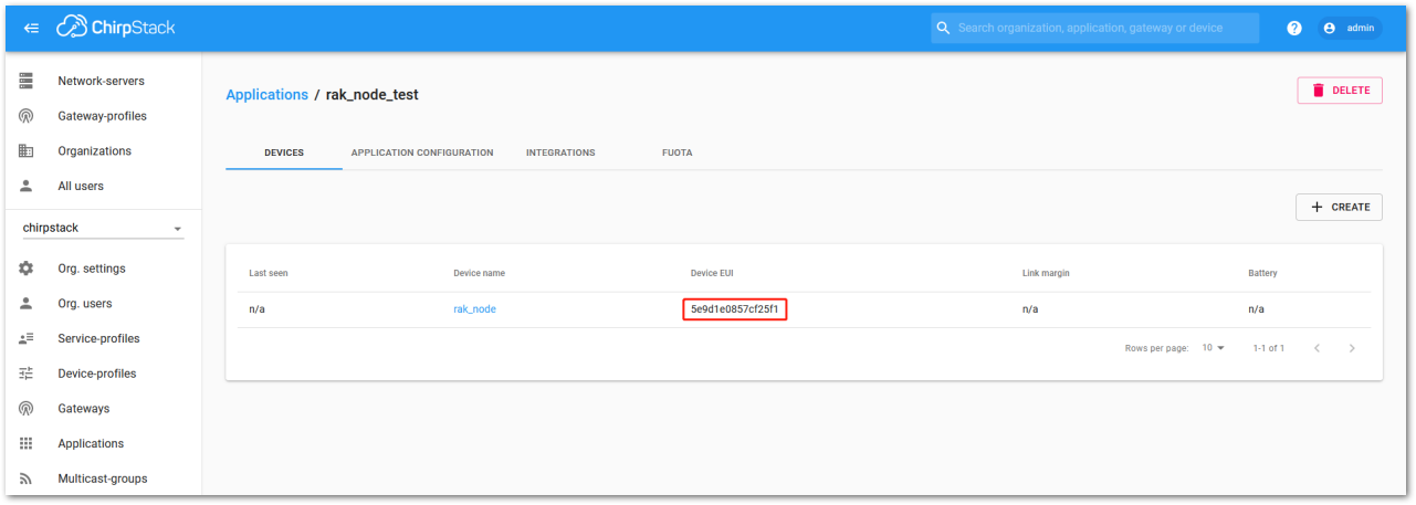 Figure 1: Chirpstack OTAA list of the device in the device tab
- To end the process, it is a good practice to review that the Application Key is properly associated with this device. The Application Key can be verified in the KEYS(OTAA) tab, as shown in Figure 209.
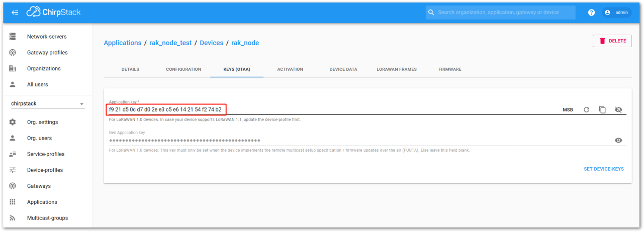 Figure 1: Application key associated with the new device
Standard OTAA mode requires the Device EUI, Application Key, and Application EUI. However, in ChirpStack's implementation, only the Device EUI and Application Key are mandatory. The Application EUI is not required and is not recorded in the Application tab. Nonetheless, you can reuse the Device EUI as the Application EUI during the node configuration.
OTAA Configuration for Chirpstack
The RAK3272-SiP Breakout Board supports a series of AT commands to configure its internal parameters and control the functionalities of the board.
- To set up the RAK3272-SiP Breakout Board to join the Chirpstack using OTAA, start by connecting the RAK3272-SiP Breakout Board to the computer (see Figure 27) and open the RAK Serial Port Tool. Select the right COM port and set the baud rate to 115200.
It is recommended to start by testing the serial communication and verify that the current configuration is working by sending these two AT commands:
AT
ATE
ATE will echo the commands you input to the board which is useful for tracking the commands and troubleshooting.
You will receive OK after entering the two commands. Once ATE is set, you will see all the commands you input along with their replies. Try entering AT again, and it should appear in the terminal followed by OK, as shown in Figure 209.
If there is no OK or any reply, verify the following:
- Check if the wiring of your UART lines is correct.
- Ensure the baud rate is properly configured to 115200.
- Confirm that the device is powered correctly.
- If using a USB port for power, make sure you are using a reliable USB cable.
 Figure 1: at+version command response
- The next step is to configure the OTAA LoRaWAN parameters in RAK3272-SiP:
- LoRa work mode: LoRaWAN
- LoRaWAN join mode: OTAA
- LoRaWAN class: Class A
- LoRaWAN region: EU868
Set the work mode to LoRaWAN.
AT+NWM=1
Set the LoRaWAN activation to OTAA.
AT+NJM=1
Set the LoRaWAN class to Class A.
AT+CLASS=A
Set the frequency/region to EU868.
AT+BAND=4
-
Based on the regional band selected, configure the sub-band of your RAK3272-SIP to align with the gateway and LoRaWAN network server. This is especially critical for regional bands such as US915, AU915, and CN470.
-
Use the
AT+MASKcommand to configure channel masking for the sub-bands. Refer to the AT Command Manual for details. -
For example, to use sub-band 2, send the command:
AT+MASK=0002.
List of band parameter options
| Code | Regional Band |
|---|---|
| 0 | EU433 (Not Supported) |
| 1 | CN470 (Not Supported) |
| 2 | RU864 |
| 3 | IN865 |
| 4 | EU868 |
| 5 | US915 |
| 6 | AU915 |
| 7 | KR920 |
| 8 | AS923-1 |
| 9 | AS923-2 |
| 10 | AS923-3 |
| 11 | AS923-4 |
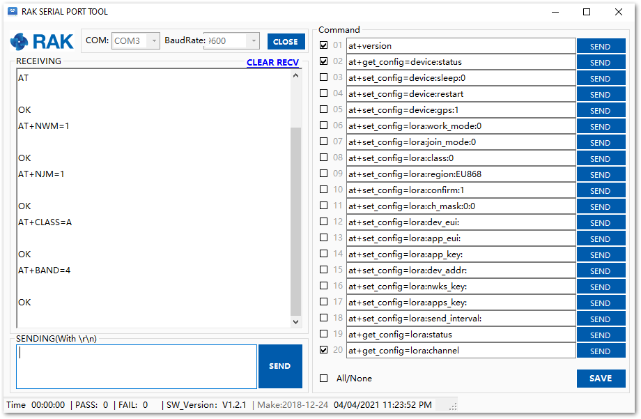 Figure 1: Configure LoRa parameters
- Set up the DevEUI and AppKey using the values provided in the ChirpStack device console.
The Application EUI parameter is not required in the ChirpStack platform; therefore, it is possible to use the same id as the Device EUI.
- Device EUI: 5E9D1E0857CF25F1
- Application EUI: 5E9D1E0857CF25F1
- Application Key: F921D50CD7D02EE3C5E6142154F274B2
Set the Device EUI.
AT+DEVEUI=5E9D1E0857CF25F1
Set the Application EUI.
AT+APPEUI=5E9D1E0857CF25F1
Set the Application Key.
AT+APPKEY=F921D50CD7D02EE3C5E6142154F274B2
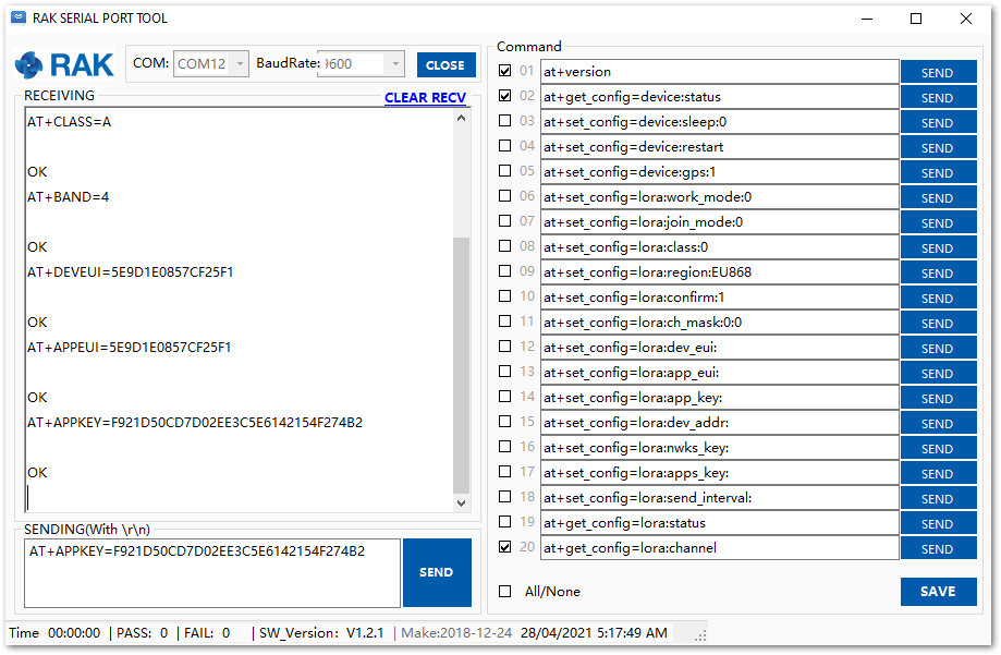 Figure 1: Configure LoRa Parameters
- After configuring the EUI and AppKey, the device is ready to join the network and send payloads.
AT+JOIN=1:0:10:8
Join command format: AT+JOIN=w:x:y:z
| Parameter | Description |
|---|---|
| w | Join command - 1: joining, 0: stop joining. |
| x | Auto-join config - 1: auto-join on powerup, 0: no auto-join |
| y | Reattempt interval in seconds (7-255) - 8 is the default. |
| z | Number of join attempts (0-255) - 0 is the default. |
- After 5 or 6 seconds, if the request is successfully received by a LoRaWAN gateway, then you should see a JOINED status reply.
-
If the OTAA device fails to join, verify that the device is within the coverage area of a functional LoRaWAN gateway configured to connect to ChirpStack. Ensure that the OTAA parameters (DevEUI and AppKey) are correct by using the commands:
AT+DEVEUI=?AT+APPKEY=?Lastly, check that the antenna is properly connected to your device.
-
After confirming these details, try joining the network again.
- With the end-device properly activated, try to send some payload after a successful join.
AT+SEND=2:12345678
Send command format: AT+SEND=<port>:<payload>
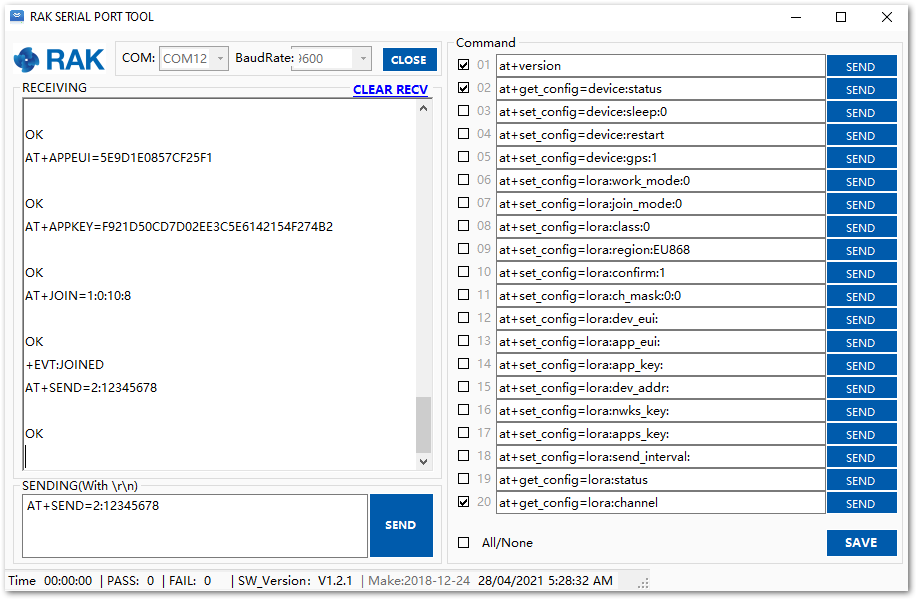 Figure 1: OTAA test sample data sent via RAK Serial Port Tool
- On the ChirpStack platform, you should see the join and uplink messages in the LORAWAN FRAMES tab, as shown in Figure 214. By convention, messages sent from nodes to gateways are considered as Uplinks while messages sent by gateways to nodes are considered as Downlinks.
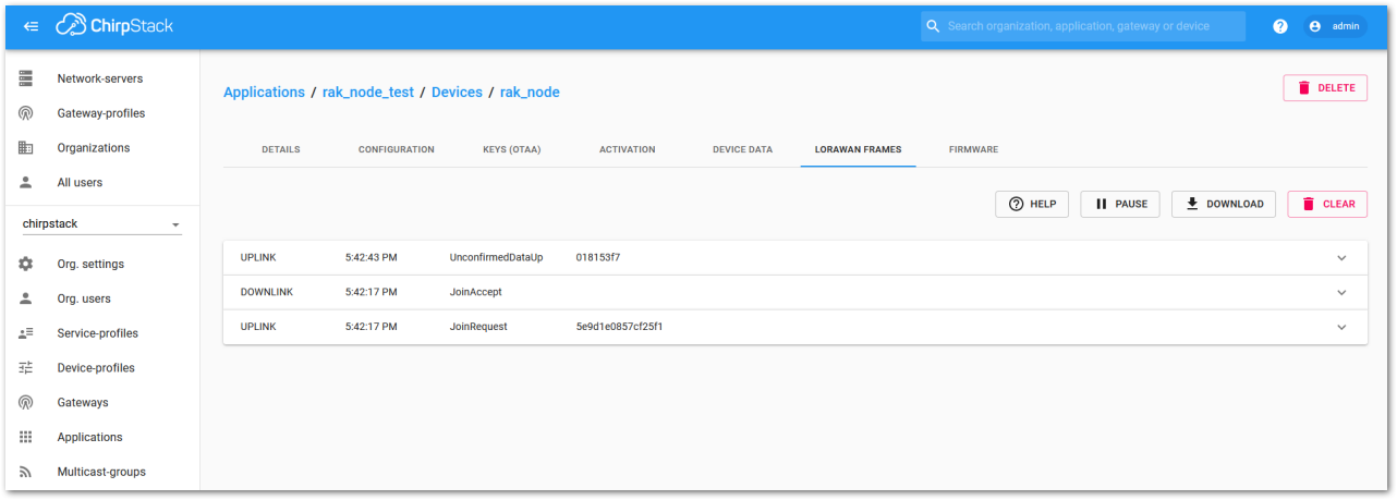 Figure 1: Chirpstack data received preview
Chirpstack ABP Device Registration
- During the registration of a new device, if you select DeviceProfile_ABP, as shown in Figure 215, then the ChirpStack platform will assume that this device will join the LoRaWAN network using the ABP mode.
Check Disable counting frame verification. During the test, when the board is restarted, the frame counting number will also be restarted from zero. This would cause a synchronization problem with the ChirpStack server treating it as a replay attack. For testing purposes, it is safe to disable this feature, but remember to activate it in a production environment.
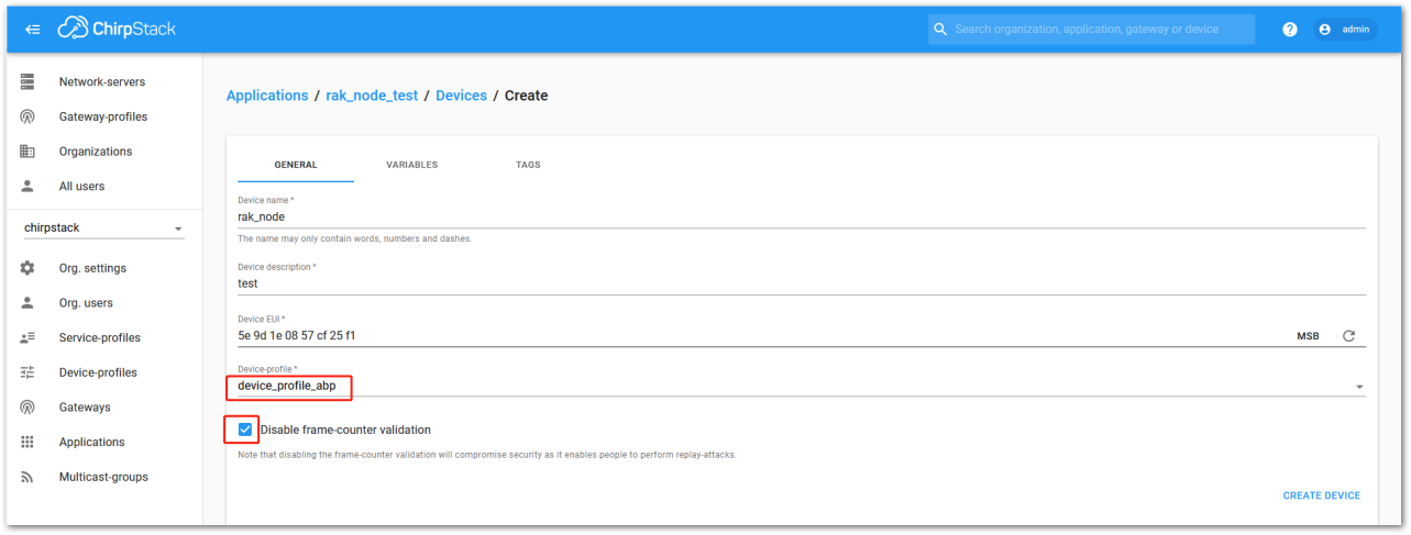 Figure 1: ChirpStack console, Configure a device
- After selecting the ABP mode, the following parameters appear in the Activation tab, then you can see that there are some parameters for ABP in the ACTIVATION item:
- Device Address
- Network Session Key
- Application Session Key
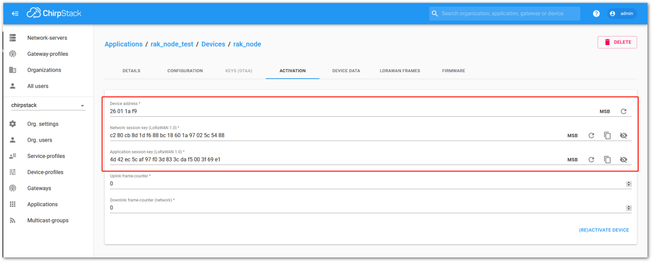 Figure 1: Chirpstack ABP activation parameters needed
- The parameters can be generated as random numbers by the platform or can be set with user values. Once these parameters are filled in properly, the process is completed by clicking on the ACTIVATE DEVICE button.
ABP Configuration for Chirpstack
- To set up the RAK3272-SiP Breakout Board to join the Chirpstack using ABP, start by connecting the RAK3272-SiP Breakout Board to the computer (see Figure 27 ) and open the RAK Serial Port Tool. Select the right COM port and set the baud rate to 115200.
It is recommended to start by testing the serial communication and verify that the current configuration is working by sending these two AT commands:
AT
ATE
ATE will echo the commands you input to the board which is useful for tracking the commands and troubleshooting.
You will receive OK after entering the two commands. Once ATE is set, you will see all the commands you input along with their replies. Try entering AT again, and it should appear in the terminal followed by OK.
If there is no OK or any reply, verify the following:
- Check if the wiring of your UART lines is correct.
- Ensure the baud rate is properly configured to 115200.
- Confirm that the device is powered correctly.
- If using a USB port for power, make sure you are using a reliable USB cable.
Figure 1: at+version command response- The next step is to configure the ABP LoRaWAN parameters in RAK3272-SiP:
- LoRa work mode: LoRaWAN
- LoRaWAN join mode: ABP
- LoRaWAN class: Class A
- LoRaWAN region: EU868
Set the work mode to LoRaWAN. It can be set to P2P as well, but by default, the device is in LoRaWAN mode.
AT+NWM=1
Set the LoRaWAN activation to ABP.
AT+NJM=0
Set the LoRaWAN class to Class A.
AT+CLASS=A
Set the frequency/region to EU868.
AT+BAND=4
-
Based on the regional band selected, configure the sub-band of your RAK3272-SIP to align with the gateway and LoRaWAN network server. This is especially critical for regional bands such as US915, AU915, and CN470.
-
Use the
AT+MASKcommand to configure channel masking for the sub-bands. Refer to the AT Command Manual for details. -
For example, to use sub-band 2, send the command:
AT+MASK=0002.
List of band parameter options
| Code | Regional Band |
|---|---|
| 0 | EU433 (Not Supported) |
| 1 | CN470 (Not Supported) |
| 2 | RU864 |
| 3 | IN865 |
| 4 | EU868 |
| 5 | US915 |
| 6 | AU915 |
| 7 | KR920 |
| 8 | AS923-1 |
| 9 | AS923-2 |
| 10 | AS923-3 |
| 11 | AS923-4 |
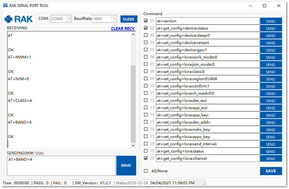 Figure 1: Configure LoRa parameters
- After the configuration of the LoRaWAN parameters, the next step is to set up the device address and session keys. You need to use the values from the TTN device console.
- Device Address: 26011AF9
- Application Session Key: 4D42EC5CAF97F03D833CDAf5003F69E1
- Network Session Key: C280CB8D1DF688BC18601A97025C5488
Set the Device Address.
AT+DEVADDR=26011AF9
Set the Application Session Key.
AT+APPSKEY=4D42EC5CAF97F03D833CDAf5003F69E1
Set the Network Session Key.
AT+NWKSKEY=C280CB8D1DF688BC18601A97025C5488
 Figure 1: Configure LoRa parameters
- After configuring the EUI and keys, the device is ready to join the network and send payloads.
AT+JOIN=1:0:10:8
Join command format: AT+JOIN=w:x:y:z
| Parameter | Description |
|---|---|
| w | Join command - 1: joining, 0: stop joining. |
| x | Auto-join config - 1: auto-join on power-up, 0: no auto-join |
| y | Reattempt interval in seconds (7-255) - 8 is the default. |
| z | Number of join attempts (0-255) - 0 is the default. |
- After 5 or 6 seconds, if the request is successfully received by a LoRaWAN gateway, you should see JOINED status reply.
Now, try to send some payload after successful join.
AT+SEND=2:12341234
Send command format: AT+SEND=<port>:<payload>
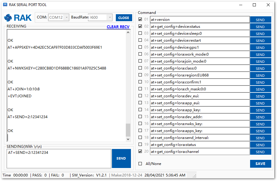 Figure 1: ABP test sample data sent via RAK Serial Port Tool
LoRa P2P Mode
This section explains how to set up and connect two RAK3272-SIP units for operation in LoRa P2P mode. The configuration of each RAK3272-SIP unit is performed by connecting the modules to a general-purpose computer using a USB-UART converter.
Each unit can be configured separately, but testing the LoRa P2P mode requires both units to be connected simultaneously. This can be achieved using one computer with two USB ports or two computers with one USB port each.
It is recommended to start by testing the serial communication and verify the current configuration is working by sending these two AT commands:
AT
ATE
ATE will echo the commands you input to the module, which is useful for tracking the commands and troubleshooting.
You will receive OK after entering the two commands. Once ATE is set, you will see all the commands you input along with their replies. Try entering AT again, and it should appear in the terminal followed by OK.
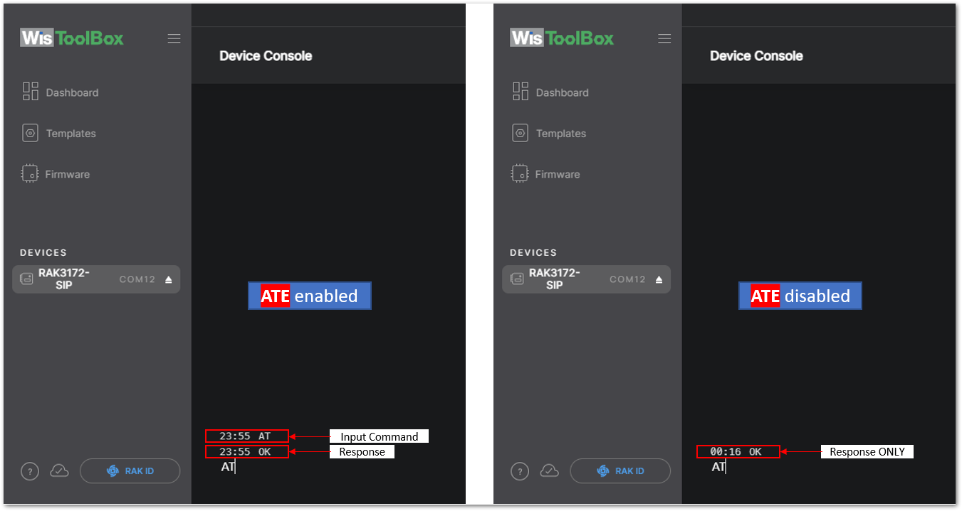 Figure 1: at+version command response
- To set up the RAK3272-SIP for LoRa P2P mode, change the LoRa network mode on both RAK3272-SIP Breakout Boards using the appropriate command.
AT+NWM=0
AT+NWM parameter mode can be either 0=LoRa P2P or 1=LoRaWAN.
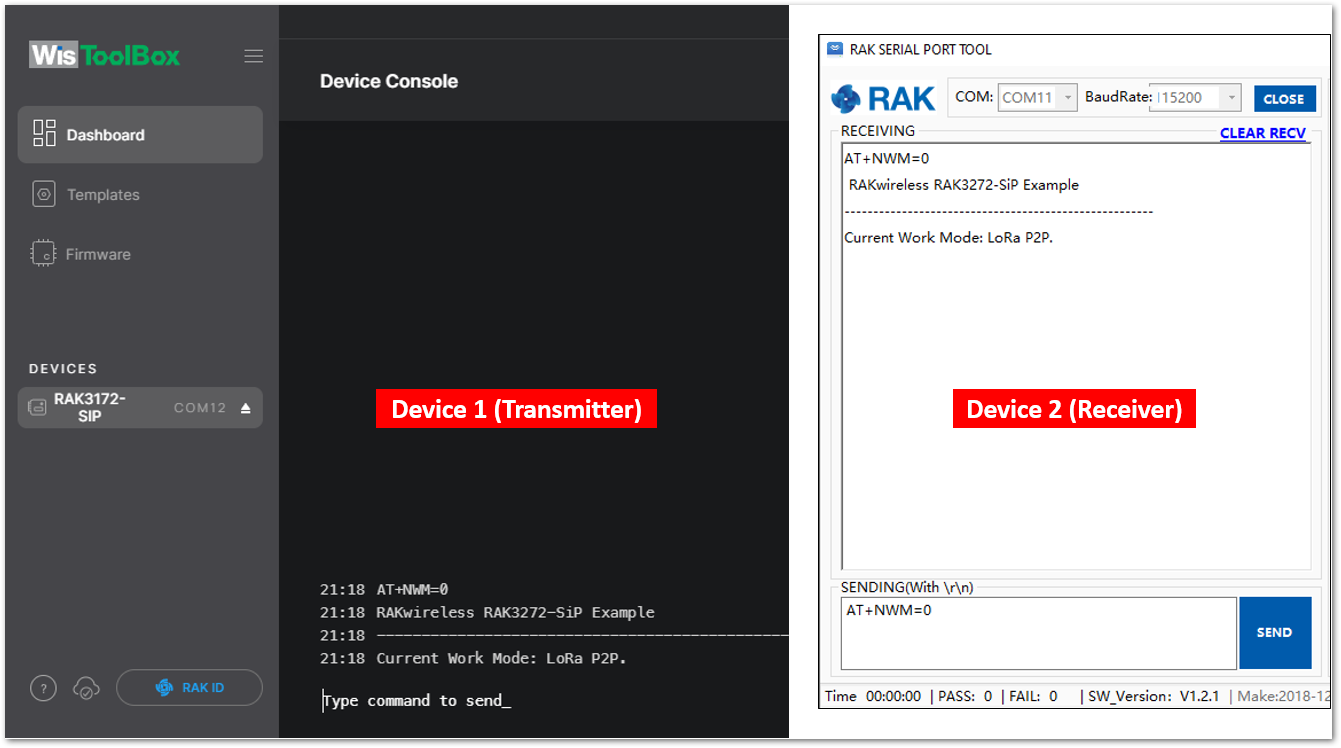 Figure 1: P2P Mode
- The device will start automatically if you change modes from LoRaWAN to LoRa P2P and vice-versa.
- You might need to input the
ATEcommand again to ensure that your succeeding commands on P2P mode echo on the terminal.
- You need to input the P2P setup on both RAK3272-SiP boards. The parameters should be exactly the same on the two boards.
AT+P2P=868000000:7:125:0:10:14
For this P2P setup, the LoRa parameters are the following:
- Link frequency: 868000000 Hz
- Spreading factor: 7
- Bandwidth: 125 kHz
- Coding Rate: 0 = 4/5
- Preamble Length: 10
- Power: 14 dBm
Refer to the P2P Mode section of the AT command documentation to learn more about the definition of the parameters used and the individual commands if you want specific parameter changed.
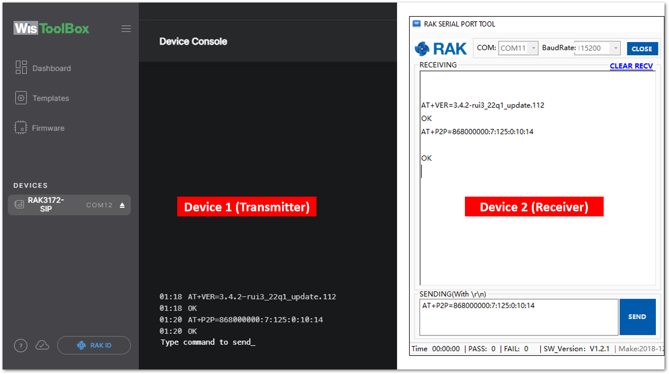 Figure 1: Configure P2P in both RAK3272-SiP Module
- To set one module as the receiver (RX), set the value of the P2P receive command.
LoRa P2P default setting is Transmitter (TX) mode. This consumes lower power compared to Receiver (RX) mode where the radio is always listening for LoRa packets.
a. P2P LoRa RX configurable duration value is from 1 to 65533 ms. In this example, the device will listen and wait for LoRa P2P Packets for 30000 ms or 30 seconds. It will automatically disable RX mode and switch to TX mode after the timeout. If the device did not receive any packets within the time period, then the callback after timeout is +EVT:RXP2P RECEIVE TIMEOUT.
AT+PRECV=30000
b. If the AT+PRECV value is set to 65535, the device will listen to P2P LoRa packets without a timeout, but it will stop listening once a P2P LoRa packet is received. After receiving the packets, it will disable RX mode and automatically switch to TX mode again.
AT+PRECV=65535
c. If the AT+PRECV value is set to 65534, the device will continuously listen to P2P LoRa packets without any timeout. It will continuously stay in RX mode until AT+PRECV is set to 0.
AT+PRECV=65534
d. If the AT+PRECV value is set to 0, the device will stop listening to P2P LoRa packets. It disables LoRa P2P RX mode and switches to TX mode.
AT+PRECV=0
- With one module configured as Transmitter (TX) and the other device will be the Receiver (RX), try to send or transmit P2P payload data.
AT+PSEND= <payload>
AT_PARAM_ERRORis returned when setting the wrong or malformed value.AT_BUSY_ERRORis returned if the device is still in RX mode and you try to send or reconfigure the RX period. If theAT+PRECVcommand is set to 65534, you need to execute firstAT+PRECV=0to be able to configure again the TX and RX state and avoidAT_BUSY_ERROR.<payload>: 2~500 digit length, must be an even number of digits and character 0-9, a-f, A-F only, representing 1~256 hexadecimal numbers. For example, if the payload is like0x03, 0xAA, 0x32, therefore the AT command should beAT+PSEND = 03AA32.
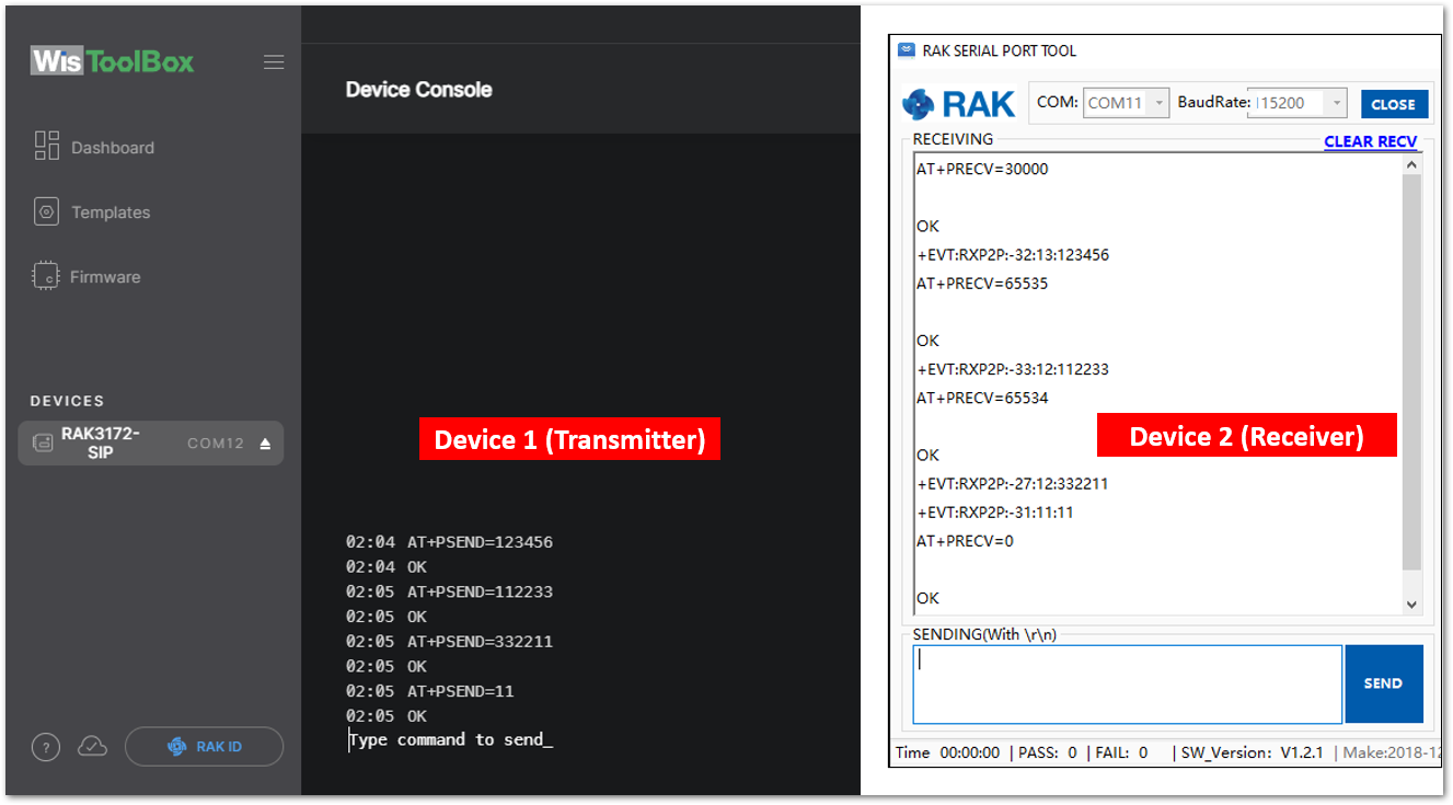 Figure 1: Configure P2P in both RAK3272-SiP Module
Miscellaneous
Upgrading the Firmware
If you want to upgrade the module to the latest firmware version, follow the instructions in this section. The latest firmware is available in the software section of the RAK3272-SiP Datasheet.
What if the RAK3272-SiP stops responding to AT commands and firmware updates?
You can recover your device by using the .hex file provided in the datasheet and uploading it via STM32CubeProgrammer. A guide on updating STM32 firmware with STM32CubeProgrammer is available in the Knowledge Hub section.
Firmware Upgrade Through UART2
Minimum Hardware and Software Requirements
Refer to the table for the minimum hardware and software required to perform the firmware upgrade via UART2.
| Hardware/Software | Requirement |
|---|---|
| Computer | A Windows/Ubuntu/Mac computer |
| Firmware File | Bin firmware file downloaded from the website |
| Others | A USB to TTL module |
Firmware Upgrade Procedure
Execute the following procedure to upgrade the firmware in Device Firmware Upgrade (DFU) mode through the USB interface.
-
Download the latest application firmware of the RAK3272-SiP.
-
Download the RAK Device Firmware Upgrade (DFU) tool.
-
Connect the RAK3272-SiP Breakout Board to the computer via a USB-Serial adapter. Refer to Figure 27.
-
Open the Device Firmware Upgrade tool. Select the serial port and baud rate (115200) of the board and click the Select Port button.
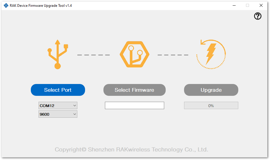 Figure 1: Device firmware upgrade tool
- Select the application firmware file of the board with the suffix .bin.
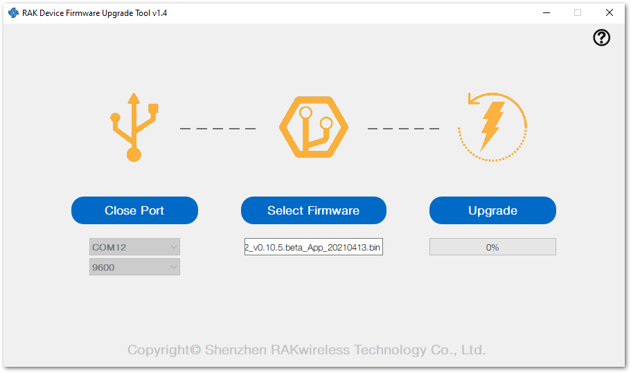 Figure 1: Select firmware
- Click the Upgrade button to upgrade the device. After the upgrade is complete, the RAK3272-SiP Breakout Board will be ready to work with the new firmware.
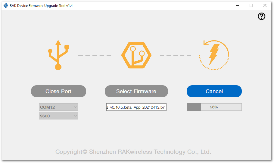 Figure 1: Firmware upgrade
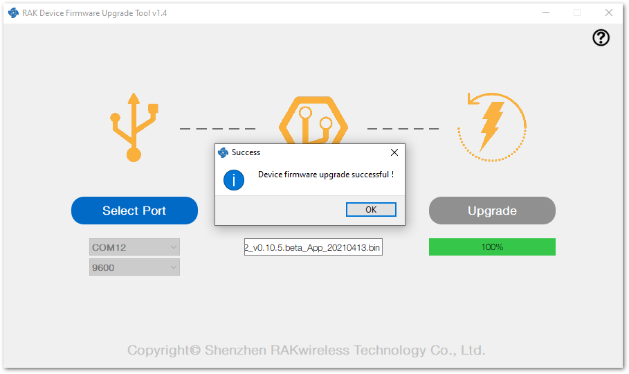 Figure 1: Upgrade successful
Arduino Installation
Go to the Arduino official website and download the Arduino IDE. You will see the multiple versions available for Windows, Linux, and Mac OS X. Choose the correct version of Arduino IDE and download it.
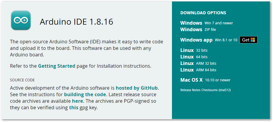 Figure 1: Arduino IDE latest version
For Windows
For Windows 10 users: Do NOT install the Arduino IDE from the Microsoft App Store. Instead, download and install the original Arduino IDE from the official Arduino website, as the version from the Microsoft App Store may encounter issues with third-party Board Support Packages.
- Install the Arduino IDE, which you just downloaded, on your Windows PC.
- Click I Agree then Next to proceed.
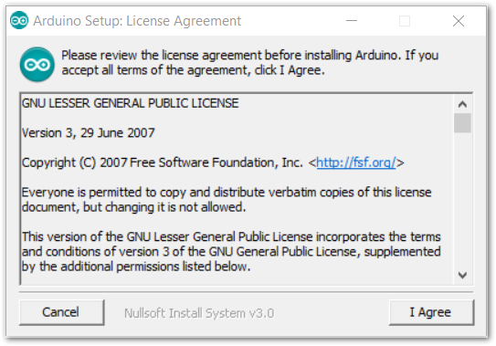 Figure 1: Arduino setup license agreement
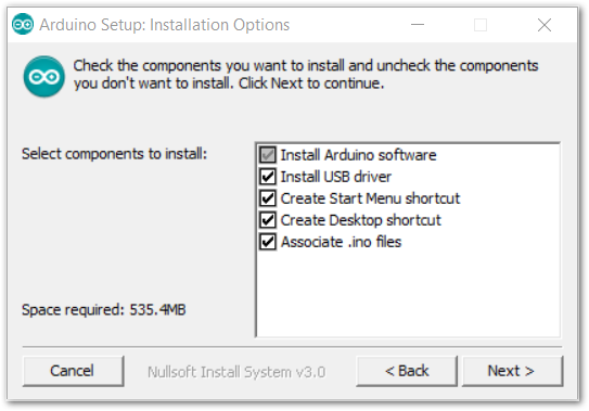 Figure 1: Arduino setup installation options
- Click Install.
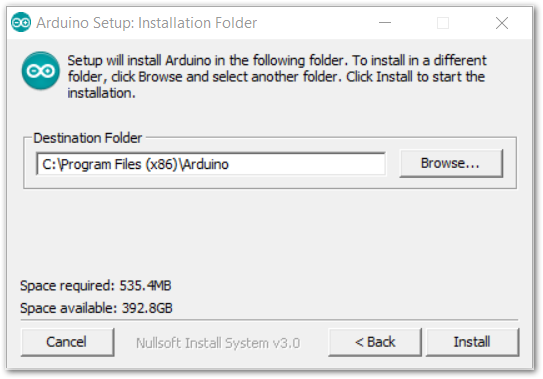 Figure 1: Install Arduino IDE
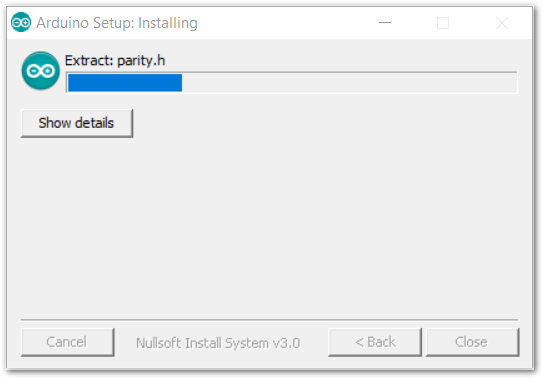 Figure 1: Ongoing installation
After 100% progress, the Arduino IDE has been installed successfully.
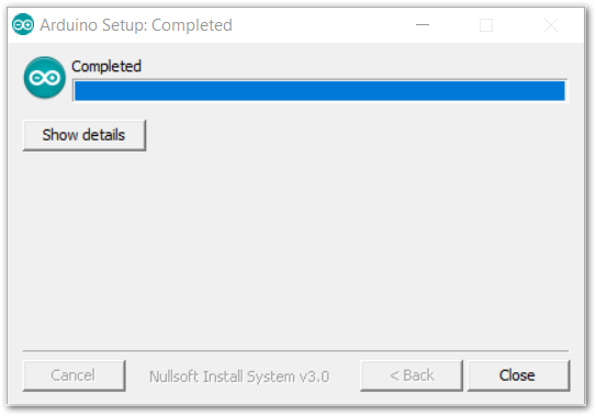 Figure 1: Successful installation
For Linux
First, you need the check the compatibility with your system and choose between the 32-bit, 64-bit, and ARM versions of the Arduino IDE for Linux.
Installing via a Tarball
After downloading the correct Arduino version, open a terminal, then run ls to check the installation file on the download folder.
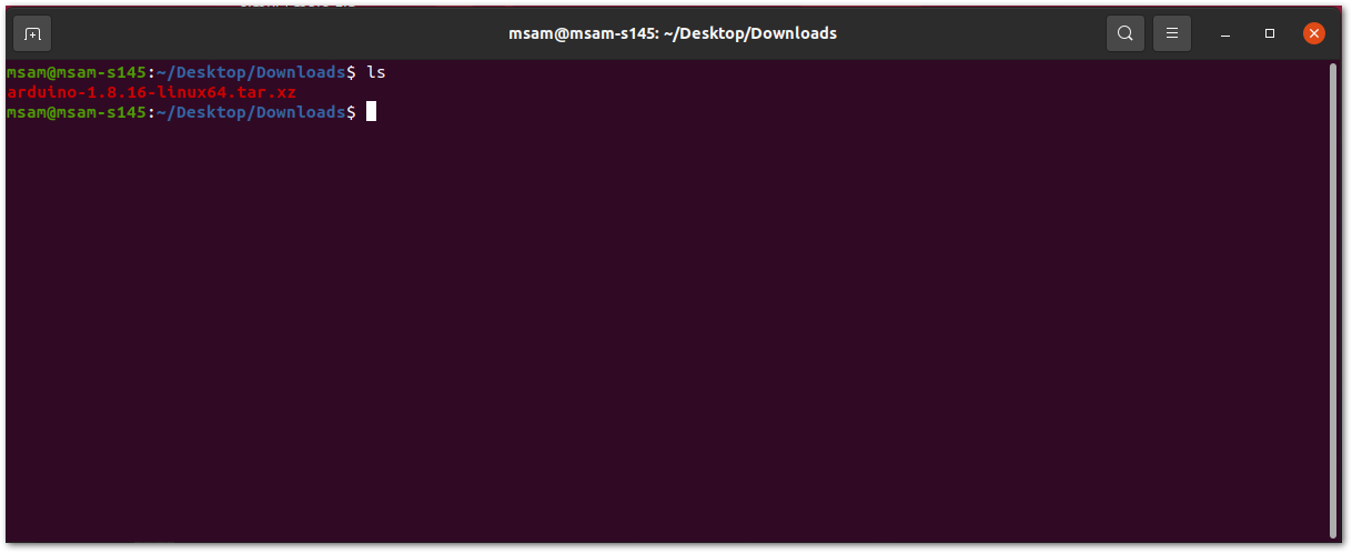 Figure 1: Check the download folder
A tarball is a type of compressed folder, like a .zip file, commonly used to distribute software in Linux. To extract the files from the tarball, change the directory to where the downloaded tarball is, then run the following:
tar xvf arduino-version.xz
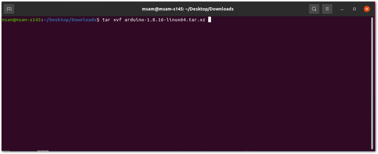 Figure 1: Tarball extract command
When the tar command finishes, run ls again. A folder named arduino-version will be created.
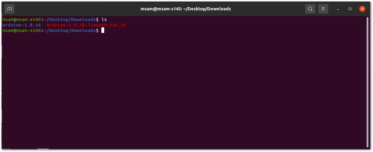 Figure 1: Arduino install folder created
Change the current directory and go to the newly created folder directory. There will be a file named install.sh in the folder. Execute sudo ./install.sh to install the Arduino IDE.
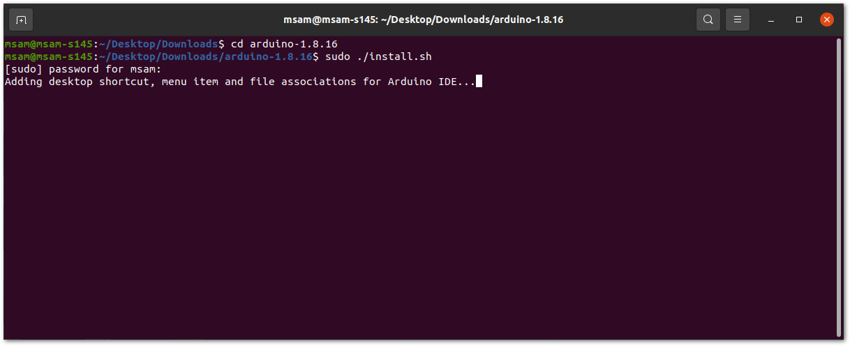 Figure 1: Arduino install script running
The sudo command temporarily elevates privileges allowing the installer to complete sensitive tasks without logging in as the root user.
For Mac OS X
In Mac OS X, the same as Linux, there is no installation process. It is just a process of decompression, then you can open Arduino IDE successfully.
Arduino IDE Parts Guide
Figure 239 shows the five (5) parts of Arduino IDE.
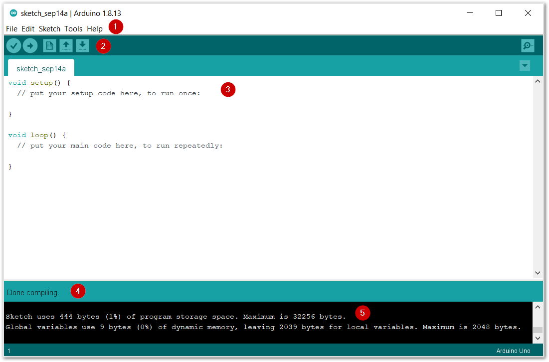 Figure 1: Arduino IDE
- IDE Option Menu
You can configure some general parameters such as the serial port, the board information, the libraries, the edit parameters, and so on.
- Operating Buttons
The operating buttons have five operations:
- Verify/Compile the source code;
- Upload the compiled code into WisBlock;
- Open a New Arduino IDE window or existing application;
- Save the current application.
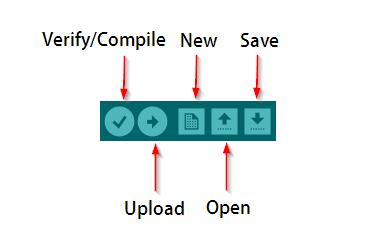 Figure 1: Operation buttons
- Code Area
Edit the source code which will be compiled and uploaded into WisBlock later in this area.
-
State Area
-
Output Message Area See the output message in this area, whether it's failure or success information.