RAK3272S Breakout Board Datasheet
Overview
Description
RAK3272S Breakout Board is designed to provide easy access to the board's pins, streamlining development and testing. Its footprint enables the RAK3172 stamp module pins to be routed to 2.54 mm headers.
The board itself has the RAK3172 at its core, integrating a STM32WLE5CC chip. It has an ultra-low power consumption of 1.69 uA in sleep mode.
This module complies with Class A, B, and C of LoRaWAN 1.0.3 specifications. It also supports LoRa Point-to-Point (P2P) communication mode, which helps you in implementing your own customized LoRa network quickly.
Features
- Based on RAK3172
- Custom firmware using Arduino via RUI3 API
- I/O ports: UART/I2C/GPIO/SPI
- Serial Wire Debug (SWD) interface
- Module size: 25.4 mm x 32.3 mm
- Ultra-low-power consumption of 1.69 uA in sleep mode
- Supply Voltage: 2.0 V ~ 3.6 V
- Temperature Range: -20° C ~ 85° C
Specifications
Overview
The top view of the RAK3272S Breakout Board is shown in Figure 1.
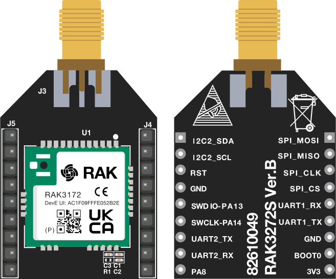 Figure 1: RAK3272S Top and Bottom View
Hardware
The hardware specification is categorized into five (5) parts. It discusses the interfacing, pinouts, and their corresponding functions and diagrams. It also covers the electrical and mechanical parameters of the board, including the tabular data of the functionalities and standard values.
Interface
SWD Programming Interface
When programming via a ST-Link tool, it is required to have the following four pins connected to your ST-Link tool:
- 3V3
- SWDIO
- SWCLK
- GND
UART Interface
This board provides two UART interfaces:
- UART1: Can be used for AT commands if configured via RUI3 Serial Port Mode.
- UART2/LPUART1: Supports AT commands and firmware updates.
I2C and SPI Interface
Only one I2C and SPI interface of RAK3272S:
- I2C2
- SPI1
RF Interface
J3 is soldered to the antenna connector. Depending on your choice, it comes with either SMA or IPEX style connector. Make sure to select the one you need when ordering.
Pin Definition
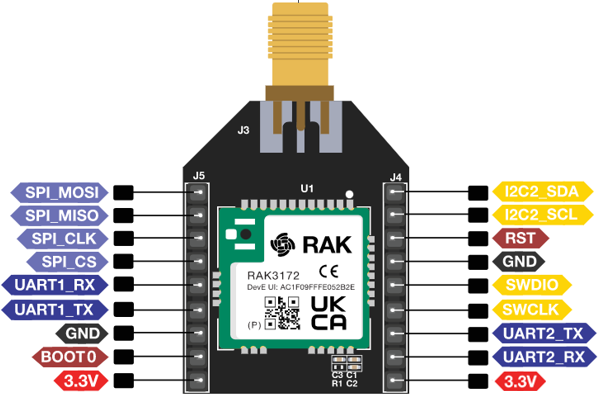 Figure 1: RAK3272S Breakout Board Pinout
The tables below show the pin definition of the RAK3272S Breakout Board:
J5 Pin Definitions
| Pin No. | Name | Description | STM32WLE5CC Pin |
|---|---|---|---|
| 1 | SPI_MOSI | GPIO and SPI (MOSI) | PA7 |
| 2 | SPI_MISO | GPIO and SPI (MISO) | PA6 |
| 3 | SPI_CLK | GPIO and SPI (CLK) | PA5 |
| 4 | SPI_CS | GPIO and SPI (NSS) | PA4 |
| 5 | UART1_RX | UART1 Interface | PB7 |
| 6 | UART1_TX | UART1 Interface | PB6 |
| 7 | GND | Ground | - |
| 8 | BOOT0 | Boot0 mode enable pin - high active | - |
| 9 | 3V3 | Power Supply | - |
J4 Pin Definitions
| Pin No. | Name | Description | STM32WLE5CC Pin |
|---|---|---|---|
| 1 | I2C2_SDA | I2C2 interface | PA11 |
| 2 | I2C2_SCL | I2C2 interface | PA12 |
| 3 | RST | MCU Reset | - |
| 4 | GND | Ground | - |
| 5 | SWDIO | SWD debug pin (SWDIO) | PA13 |
| 6 | SWCLK | SWD debug pin (SWCLK) | PA14 |
| 7 | UART2_TX | UART2/LPUART1 Interface (AT Commands and FW Update) | PA2 |
| 8 | UART2_RX | UART2/LPUART1 Interface (AT Commands and FW Update) | PA3 |
| 9 | 3V3 | *Power Supply (check warning) | - |
-
The J4 pin definition table applies to RAK3272S VerC. For RAK3272S VerB, note that pin 9 is not 3V3 but is instead connected to PA8.
-
A dedicated internal SPI interface, called SUBGHZSPI, is used for communication with the RF subsystem of the STM32WLE5CC.
RF Characteristics
The RAK3272S module supports the LoRaWAN bands listed in the table below. When purchasing a RAK3272S module, ensure you specify the correct core module, RAK3372PL or RAK3372, based on your region. The L suffix indicates compatibility with low-frequency regions, while modules without a suffix (RAK3172P) are designed for high-frequency regions.
| Module | Core Module | Region | Frequency |
|---|---|---|---|
| RAK3272SL | RAK3172PL | Europe | EU433 |
| RAK3172PL | China | CN470 | |
| RAK3272S | RAK3172P | Europe | EU868 |
| RAK3172P | North America | US915 | |
| RAK3172P | Australia | AU915 | |
| RAK3172P | Korea | KR920 | |
| RAK3172P | Asia | AS923-1/2/3/4 | |
| RAK3272P | India | IN865 | |
| RAK3272P | Russia | RU864 |
Electrical Characteristics
Power Consumption
| Feature | Condition | Minimum | Typical | Maximum | Unit |
|---|---|---|---|---|---|
| Operating Current | TX Mode | 87 @ 20 dBm, 868 MHz | - | - | mA |
| RX Mode | 5.22 | - | - | mA | |
| Sleep Current | EU868 | - | 1.69 | - | uA |
| CN470 | - | 1.69 | - | uA |
Operating Voltage
| Feature | Minimum | Typical | Maximum | Unit |
|---|---|---|---|---|
| VCC | 2.0 | 3.3 | 3.6 | V |
Mechanical Characteristics
Figure 4 show RAK3272S board dimensions.
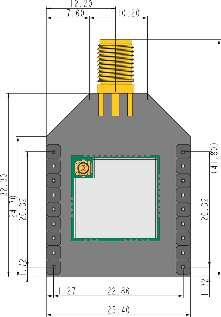 Figure 1: RAK3272S Mechanical Dimensions
Schematic Diagram
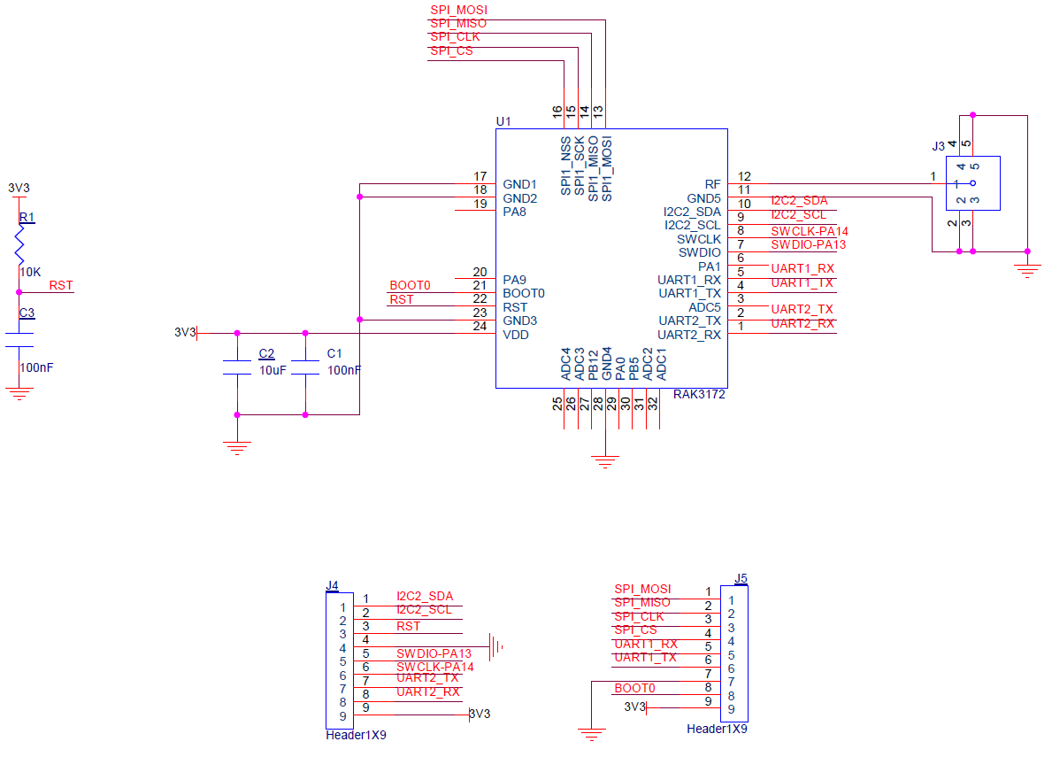 Figure 1: RAK3272S Schematic Diagram
Software
Download the latest firmware of the RAK3272S Breakout Board provided below. RAK3272SL and RAK3272S use the same firmware, and it will automatically detect the variant of the module being used.
The bin file contains only the application code and requires the RAK DFU Tool to upload it to the module.
The hex file includes both the bootloader and the application code. To upload it, you need to use the STM32CubeProgrammer.
Uploading the .hex file using STM32CubeProgrammer will erase all configured data on the device.
RAK3272S uses UART2 serial pins to upload the latest firmware.
The RAK3272S should automatically enter BOOT mode when the firmware is uploaded using the RAK DFU Tool or WisToolBox.
If BOOT mode is not initiated, send the AT+BOOT command to start bootloader mode.
Firmware / OS
| Model | Version | Source |
|---|---|---|
| RAK3272S(.bin) | RUI3 (default baudrate = 115200) | Download |
| RAK3272S(.hex) | RUI3 (default baudrate = 115200) | Download |
| RAK3272S | DEPRECATED V1.0.4 (default baudrate = 9600) | Download |
- Some RAK3172 devices come with older firmware versions (v1.0.4 and below) that are not based on RUI3 (RAKwireless Unified Interface V3).
- If the host microcontroller code is based on older firmware, the RAK3172 AT Command Migration Guide provides a detailed explanation of the key differences between the two AT command sets.
Certification
For CE and FCC certifications we provide an AT command guide.
You can find it in our RUI3 documentation or get it from our Download Center.