RAK4200 Evaluation Board Quick Start Guide
Prerequisites
What Do You Need?
Before going through each and every step in the installation guide of the RAK4200 Evaluation Board, make sure to prepare the necessary items listed below:
- RAK4200 Evaluation Board
- Micro USB Cable
- LoRA gateway in range, for testing
- Windows PC
- RAKDAP1 DAPLink Tool
To have an optimal antenna matching for the Low and High LoRa bands, there are two types of modules with different hardware. The L-type module only works for the 433 MHz and 470 MHz LoRa bands. The H type module is for the 868 MHz to 923 MHz (the rest of the spectrum). Note that the hardware is specific for your selected band and can't be changed.
What's included in the Package?
- 1pc - RAK4200 Evaluation Board
- 1pc - Micro USB Cable
- 1pc - LoRa Antenna (iPEX)
- 2pcs - 4-pin Header
- 13pcs - Dupont Lines
This device released by RAKwireless is already pre-loaded with its latest firmware upon manufacturing. If you want to have your device firmware burned or upgraded, refer to the documentation below:
Interfacing with RAK4200 Evaluation Board
To interface with the RAK4200 Evaluation Board with your Windows PC, you need to download the RAK Serial Port Tool.
Before powering the RAK4200 Evaluation Board, you should install the LoRa antenna first. Not doing so might damage the board
- Connect your RAK4200 Evaluation Board to your Windows PC using the provided micro USB cable.
 Figure 1: RAK4200 Evaluation Board to Laptop Connection
- Open the RAK Serial Port Tool:
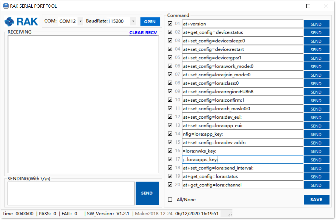 Figure 1: RAK Serial Port Tool
- Go to Device Manager by pressing Windows + R and typing devmgmt.msc or search in the Start Menu.
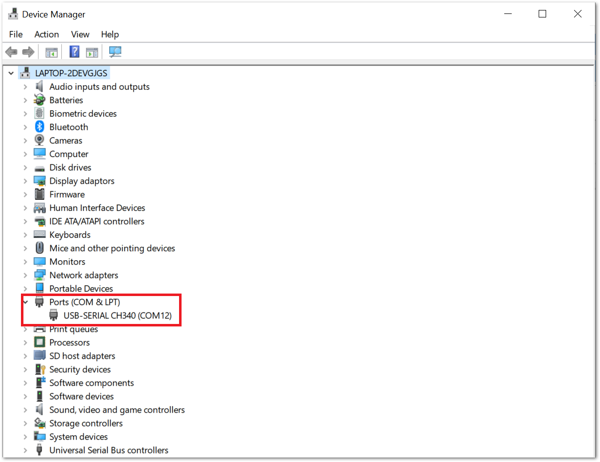 Figure 1: Device Manager
- Look for Ports (COM & LPT) and find the name USB-SERIAL CH340. Take note of the COM Port Number.
If you didn't find any port with the name USB-SERIAL CH340, make sure you have installed the CH340 drivers on your Windows PC.
- Choose the correct Port Number from the Device Manager, select 115200 as the baud rate then click the Open button:
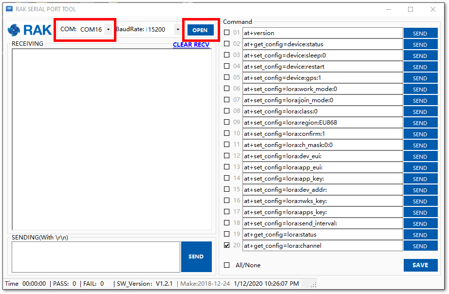 Figure 1: Correct Port Number and Baud rate
Connecting to The Things Network (TTN)
The Things Network is about enabling low-power devices to be used in long-range gateways that connect to an open-source, decentralized network and exchange data with Applications. Learn more about The Things Network.
In this section, you will be connecting the RAK4200 Evaluation Board to The Things Network (TTN). If you don't have an account yet, head on to https://www.thethingsnetwork.org/ and create one. Once done, log in to your account then go to the console, as shown in Figure 5.
 Figure 1: The Things Network Home Page
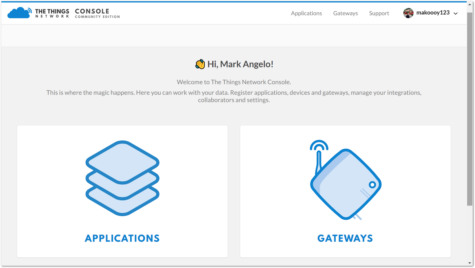 Figure 1: TTN Console Page
- Choose "APPLICATIONS"
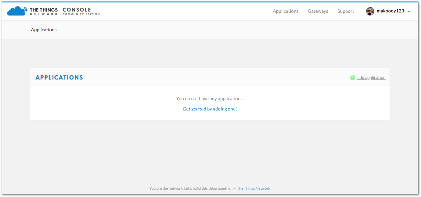 Figure 1: Application Page
- Click the "add application" button
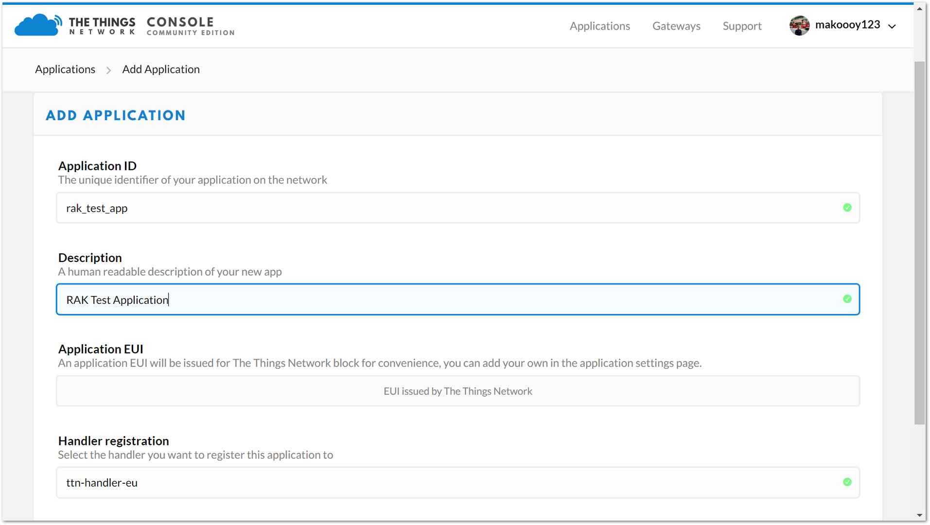 Figure 1: Adding an Application
Here are the things that you should take note of in adding an application:
-
Application ID: A unique ID on the TTN network that should be in lower case with no spaces.
-
Description: This is a short and concise human-readable description of your application.
-
Application EUI: Automatically generated by TTN.
-
Handler Registration: Select the handler you want to register this application to.
-
After you fill in the necessary information, press the "Add application" button at the bottom of this page. If you see the following page, this means that you have successfully registered your application.
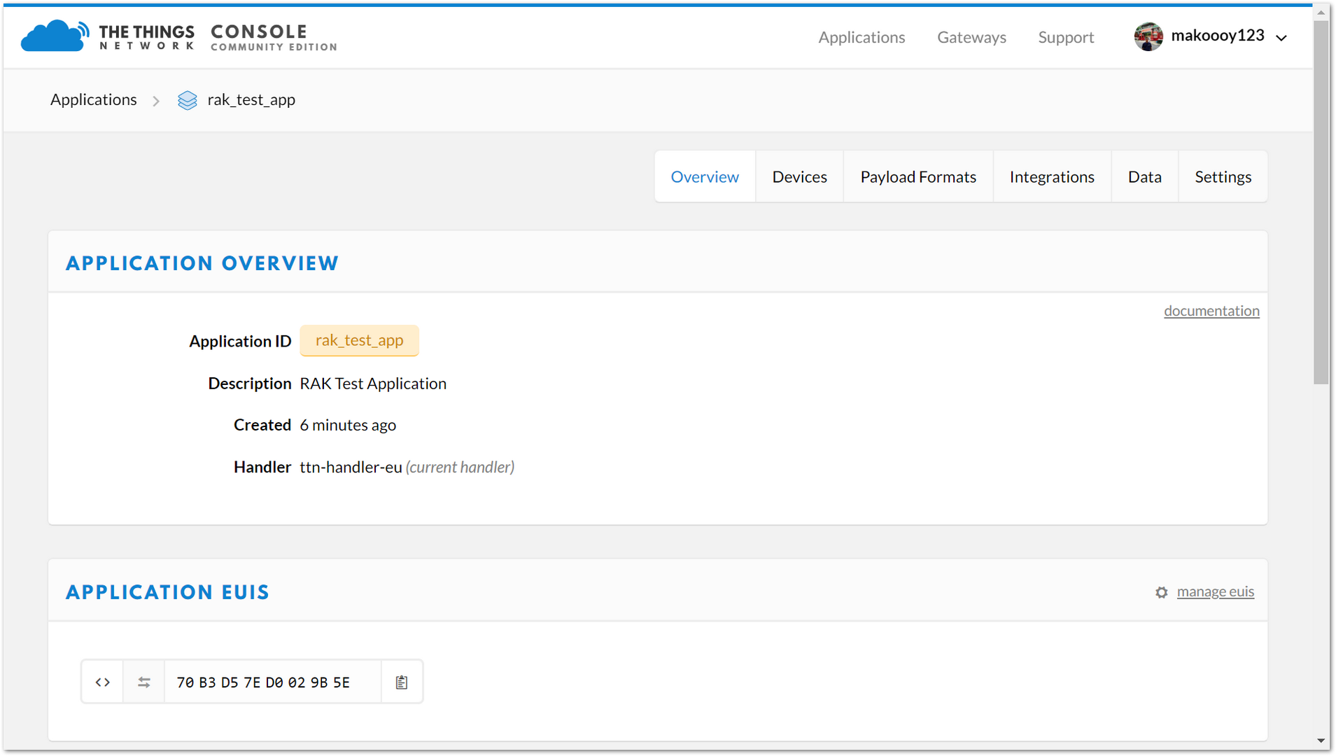 Figure 1: Application Overview
- Scroll down until you see the Devices section, or you can also click the "Devices" button at the top.
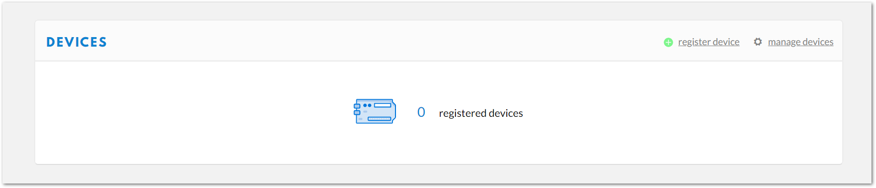 Figure 1: Device Section
- Click "Register device"
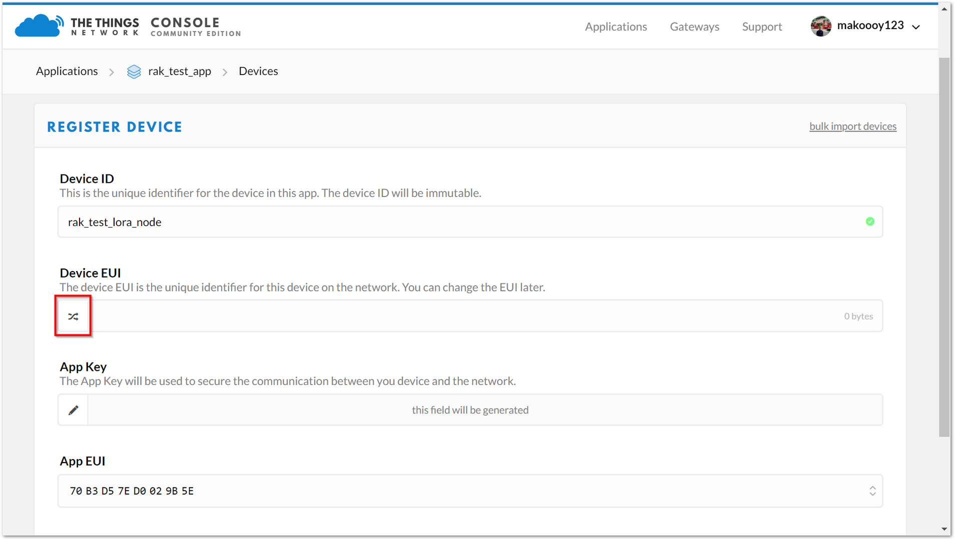 Figure 1: Add your Device
Here are the things that you should take note of when registering your device:
- Device ID: a unique identifier for your RAK4200 Evaluation Board in your application, and must be entered manually.
- Device EUI: a unique identifier for your device in the network. You can change it later if you want.
Click the following icon and the Device EUI will be automatically generated. The App Key should be in auto-generation mode by default.
- Lastly, click the Register button. Now, your device is registered under the corresponding application.
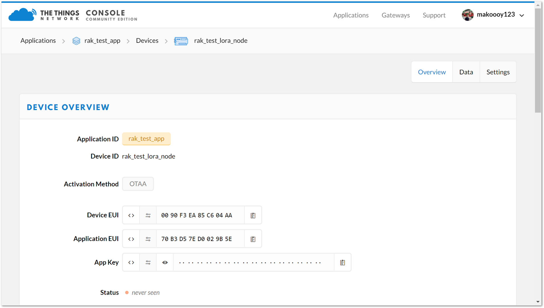 Figure 1: Device Overview
Depending on which authentication method you want to use, proceed to either the OTAA Mode or ABP mode section.
OTAA Mode
When setting up a new device in TTN, its default is to join in OTAA mode. For this configuration, you need the following three parameters: Device EUI, Application EUI, and App Key. You can get them all from the Overview page.
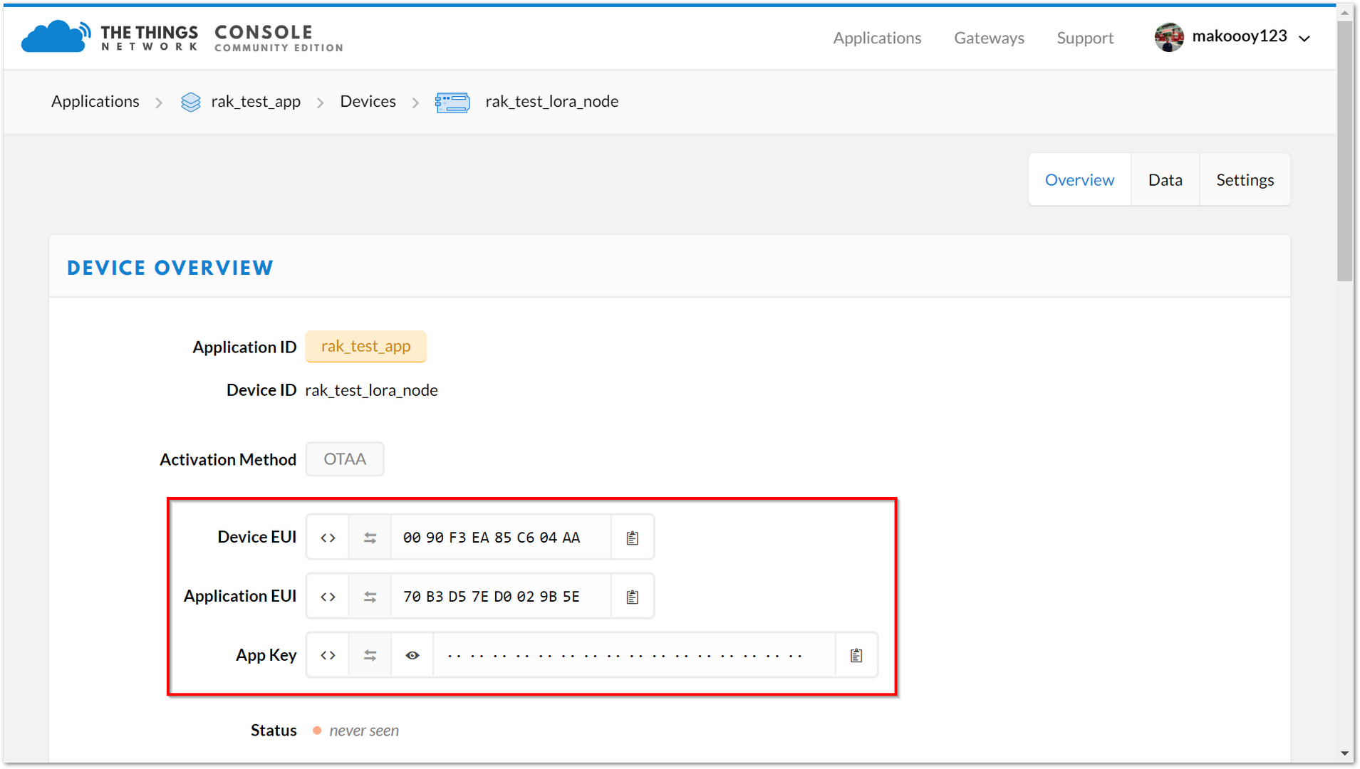 Figure 1: Device Overview Parameters
As an example, join in OTAA mode, EU868 frequency, and the default LoRa class is Class A.
- Set the LoRa join mode to OTAA:
at+set_config=lora:join_mode:0
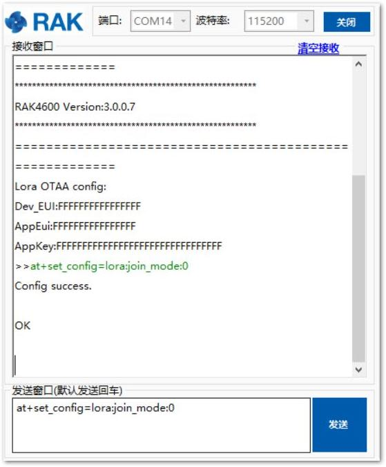 Figure 1: AT Command for OTAA LoRa Join Mode via RAK Serial Port Tool
- Set the LoRa class to Class A:
at+set_config=lora:class:0
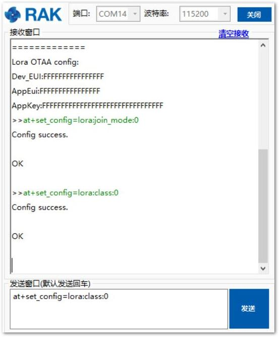 Figure 1: AT Command for OTAA LoRa Class via RAK Serial Port Tool
- Set the frequency/region to EU868:
at+set_config=lora:region:EU868
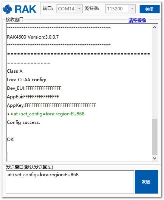 Figure 1: AT Command for OTAA LoRa Region Frequency via RAK Serial Port Tool
- Set the Device EUI:
at+set_config=lora:dev_eui:XXXX
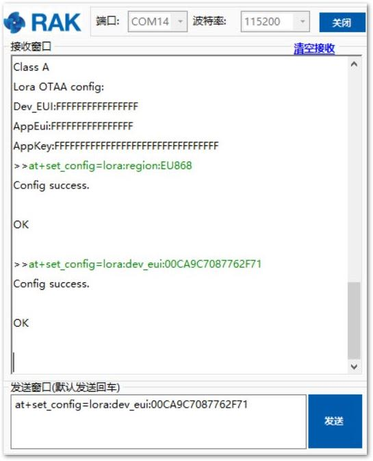 Figure 1: AT Command for OTAA LoRa Device EUI via RAK Serial Port Tool
- Set the Application EUI:
All zero value Application EUI at+set_config=lora:app_eui:0000000000000000 is not supported and will return error.
at+set_config=lora:app_eui:XXXX
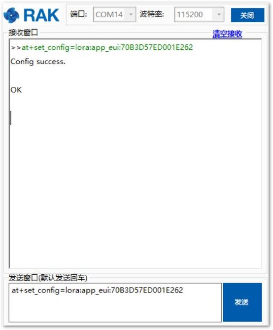 Figure 1: AT Command for OTAA LoRa Application EUI via RAK Serial Port Tool
- Set the Application Key:
at+set_config=lora:app_key:XXXX
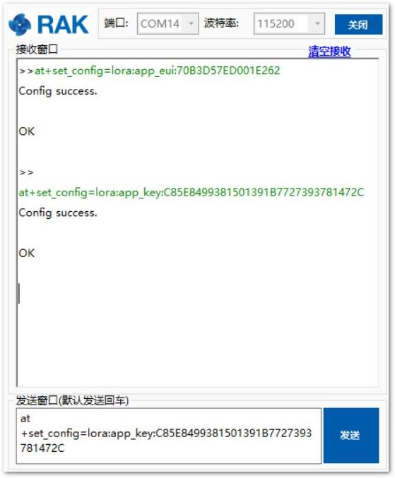 Figure 1: AT Command for OTAA LoRa Application Key via RAK Serial Port Tool
After configuring all parameters, you need to reset the RAK4200 Evaluation Board to save the parameters!
- After resetting the RAK4200 Evaluation Board, join in OTAA mode:
at+join
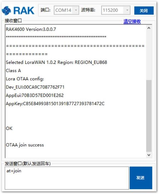 Figure 1: AT Command for OTAA LoRa Join via RAK Serial Port Tool
- Joined successfully! Try to send data from the RAK4200 Evaluation Board to TTN:
at+send=lora:2:1234567890
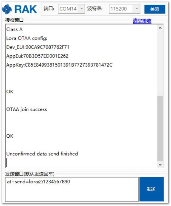 Figure 1: OTAA Test Sample Data Sent via RAK Serial Port Tool
You can see the data sent from the RAK4200 Evaluation Board on the TTN website, as shown in Figure 22.
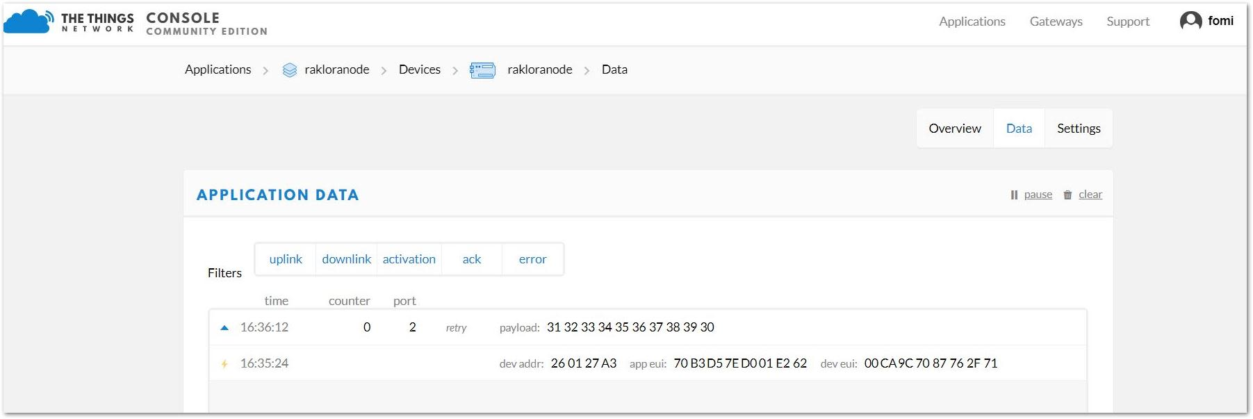 Figure 1: OTAA Test Sample Data Sent Viewed in The Things Network
ABP Mode
- First, change the activation method to ABP, as shown in Figure 23.
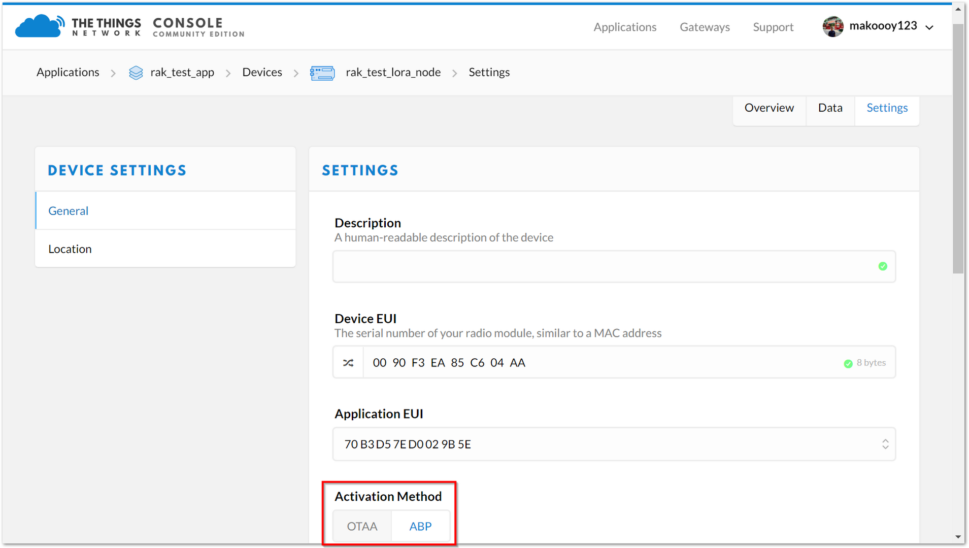 Figure 1: APB Activation in The Things Network
- Three parameters will be used to set up the RAK4200 Evaluation Board on ABP mode: Device Address, Network Session Key, and App Session Key.
Figure 1: ABP Parameters in The Things NetworkAs an example, join in ABP mode, EU868 frequency, and LoRa class A.
- If the join mode is not ABP Mode, just set the LoRa join mode to ABP as follows:
at+set_config=lora:join_mode:1
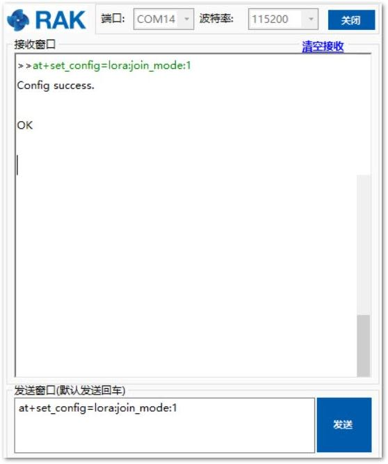 Figure 1: ABP Parameters in The Things Network
- Set the LoRa class to Class A:
at+set_config=lora:class:0
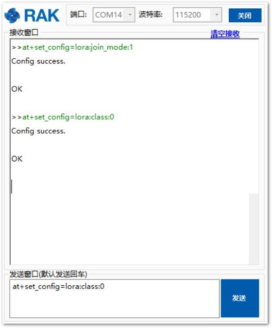 Figure 1: AT Command for ABP LoRa Class via RAK Serial Port Tool
- Set the frequency/region to EU868:
at+set_config=lora:region:EU868
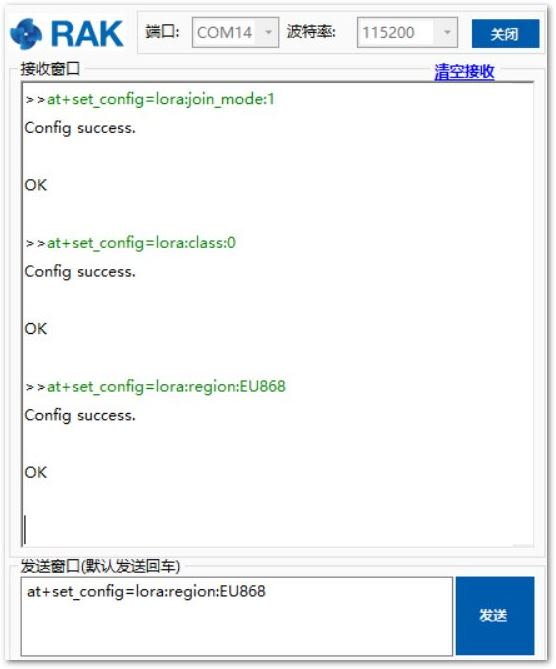 Figure 1: AT Command for ABP LoRa Class via RAK Serial Port Tool
- Set the Device Address:
at+set_config=lora:dev_addr:XXXX
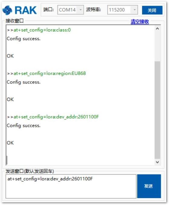 Figure 1: AT Command for ABP LoRa Device Address via RAK Serial Port Tool
- Set the Network Session Key:
at+set_config=lora:nwks_key:XXXX
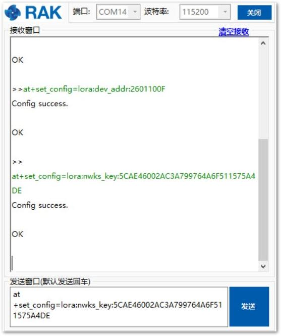 Figure 1: AT Command for ABP LoRa Network Session Key via RAK Serial Port Tool
- Set the Application Session Key:
at+set_config=lora:apps_key:XXXX
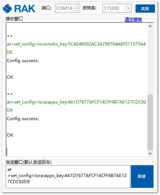 Figure 1: AT Command for ABP LoRa Application Session Key via RAK Serial Port Tool
After configuring all the parameters, you need to reset the RAK4200 Evaluation Board to save the parameters.
- After resetting your RAK4200 Evaluation Board, join in ABP mode:
at+join
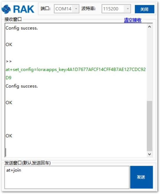 Figure 1: AT Command for ABP LoRa Join via RAK Serial Port Tool
There is no need to join in ABP mode; but, you still need to set this AT command to validate the parameters which you just set for ABP mode.
Try to send data from the RAK4200 Evaluation Board to TTN in ABP mode.
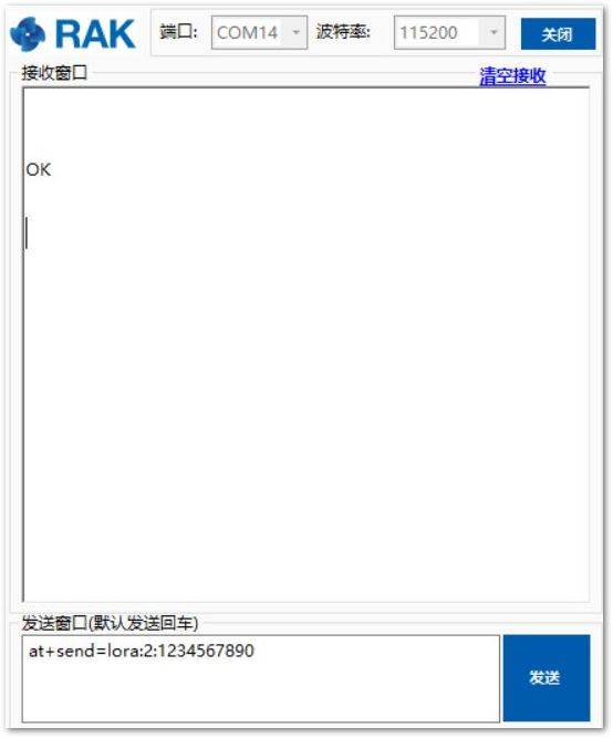 Figure 1: OTAA Test Sample Data Sent via RAK Serial Port Tool
Connecting with Chirpstack
The ChirpStack, previously known as the LoRaServer project, provides open-source components for building LoRaWAN networks. For more details, refer to ChirpStack website.
In this document, it is assumed that you are using a LoRa gateway with the ChirpStack configured successfully. If not, have a look at RAK documents for more details: RAK LPWAN Gateway.
- Open the web page of the ChirpStack, which you want to connect with, and log in.
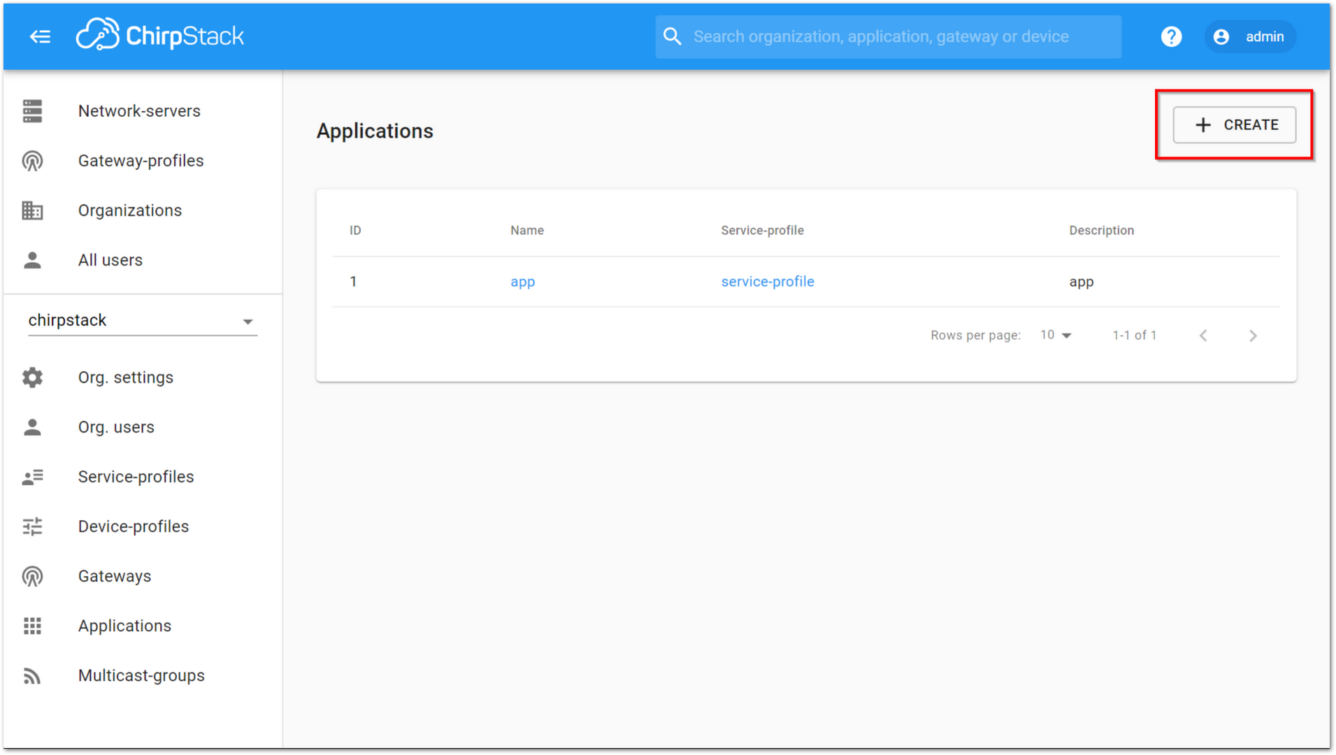 Figure 1: Chirpstack Default Window
By default, there is already one or more items on this page. You can either use it or create a new item.
- Create a new item by clicking the “CREATE” button, and filling in the necessary items.
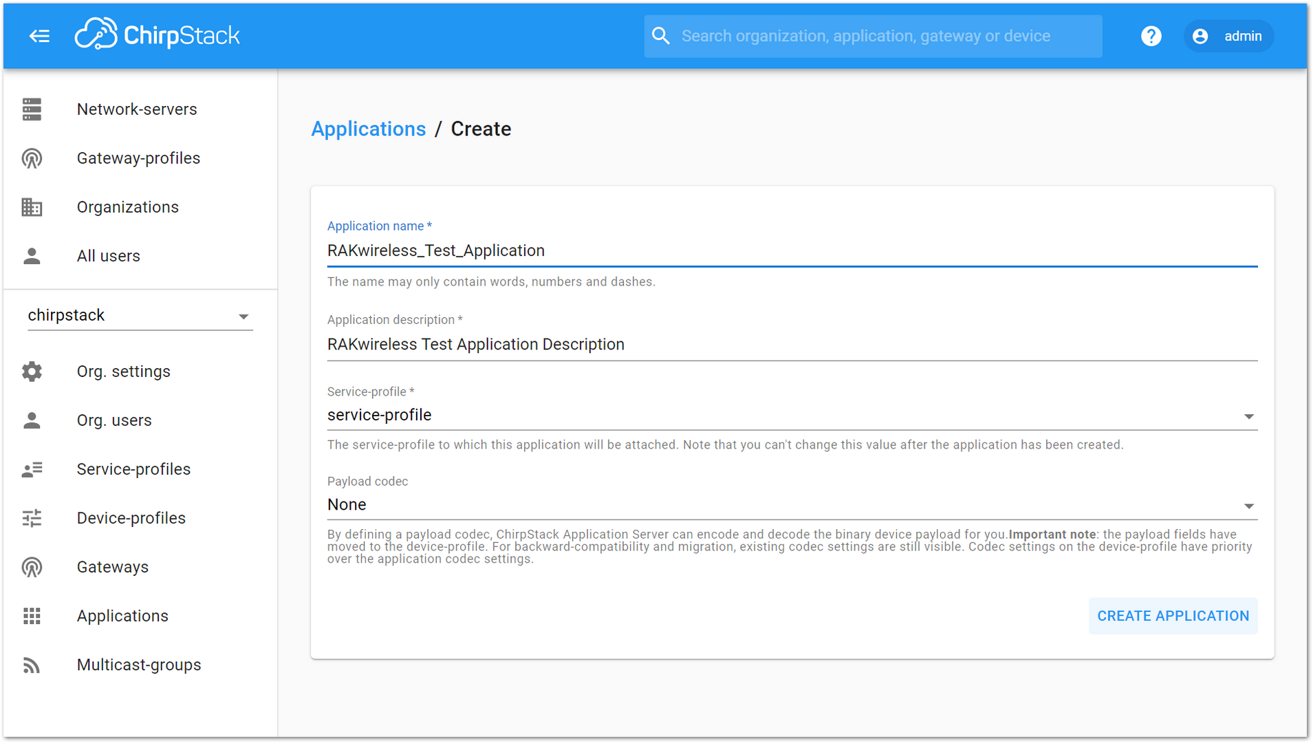 Figure 1: Chirpstack Creating Application
- Once done, click on “CREATE APPLICATION”.
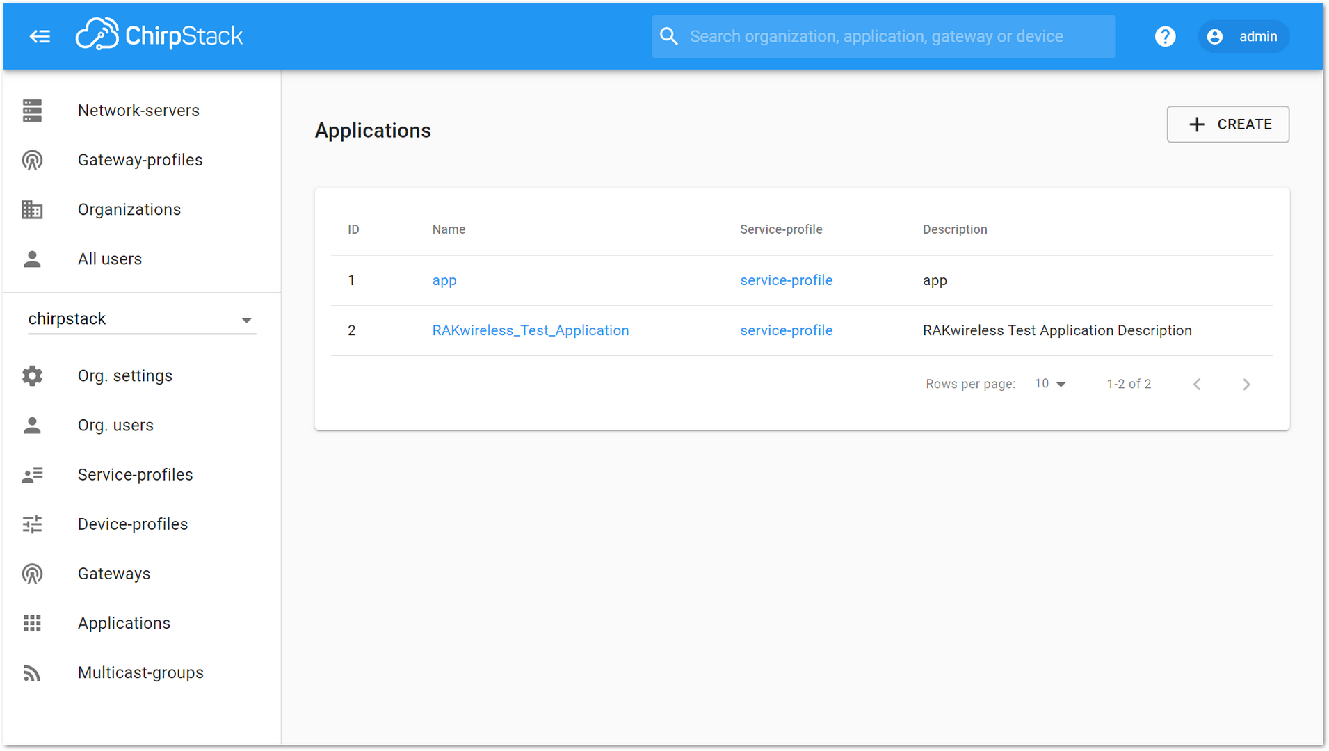 Figure 1: Chirpstack Applications Available
- The list of items is then provided the same with Figure 35. Click on the new item created.
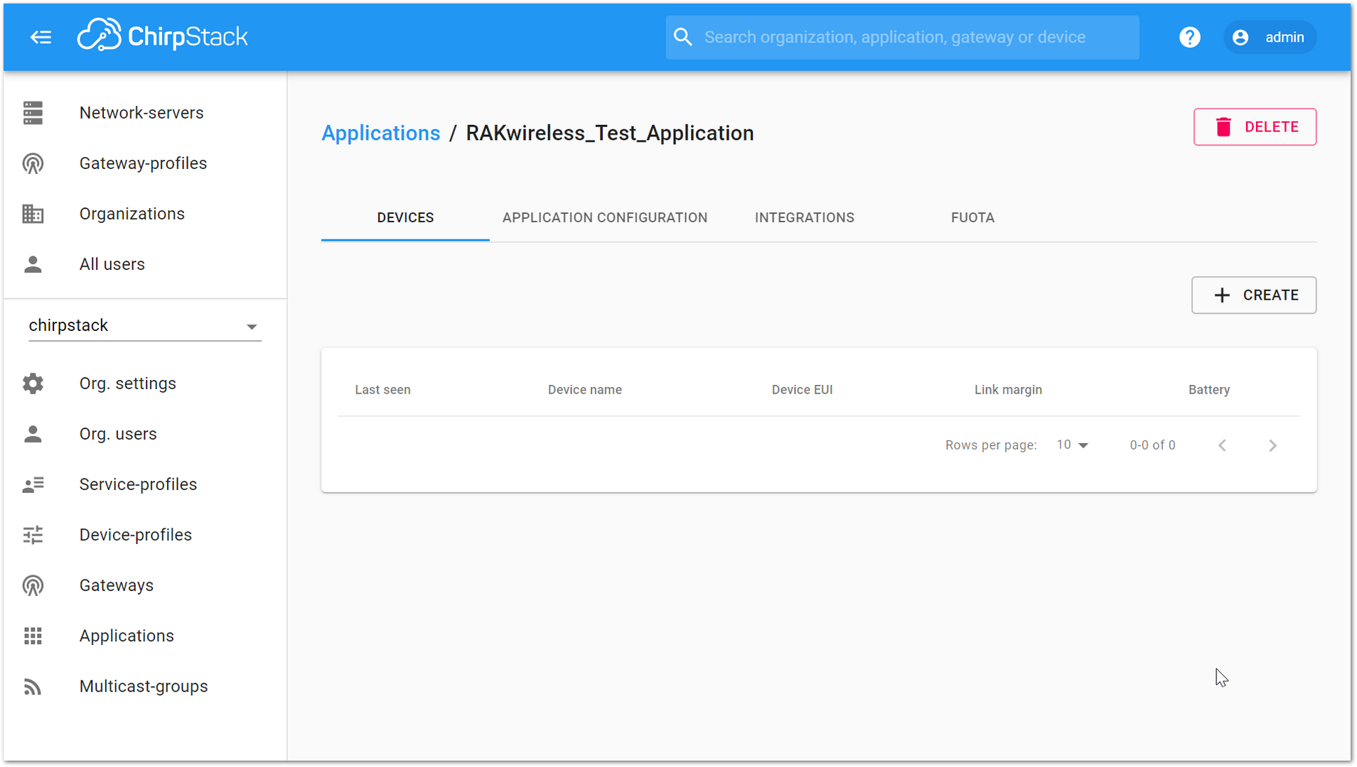 Figure 1: Applications Page in Chirpstack
- Add a node device into ChirpStack by clicking the “CREATE” button.
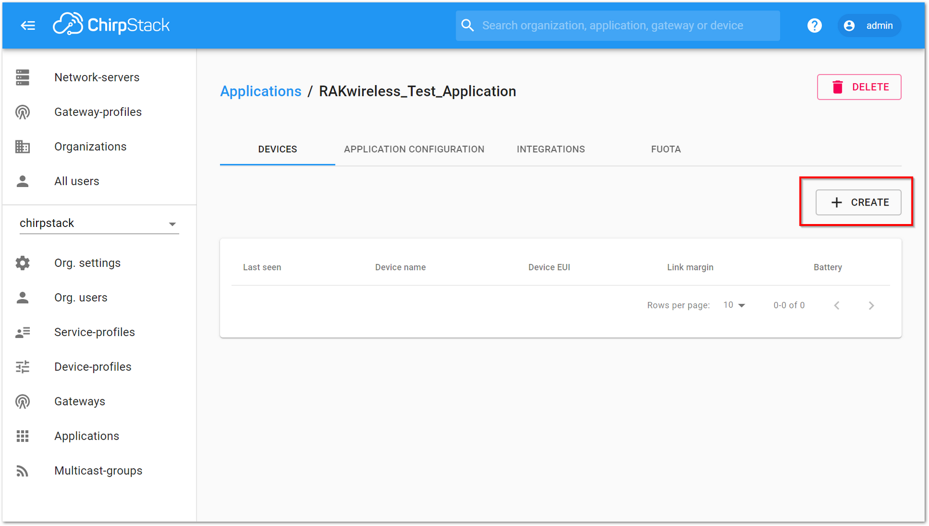 Figure 1: Chirpstack Adding Node into the RAK4200 Evaluation Board
 - Once the node is created, fill in the necessary data. You can generate a Device EUI automatically by clicking the following icon, or you can write a correct Device EUI in the edit box.
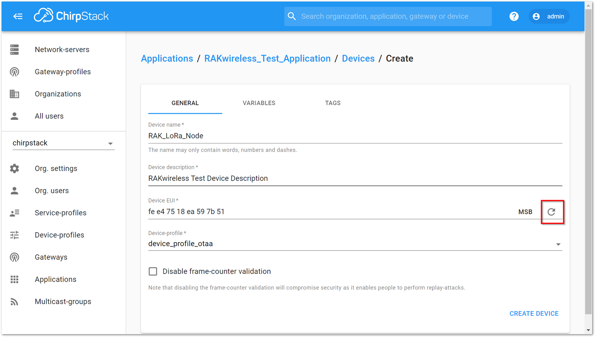 Figure 1: Chirpstack Adding Parameters in the Node
OTAA Mode
- If you select “device_profile_otaa”, it means you want to join ChirpStack in OTAA mode.
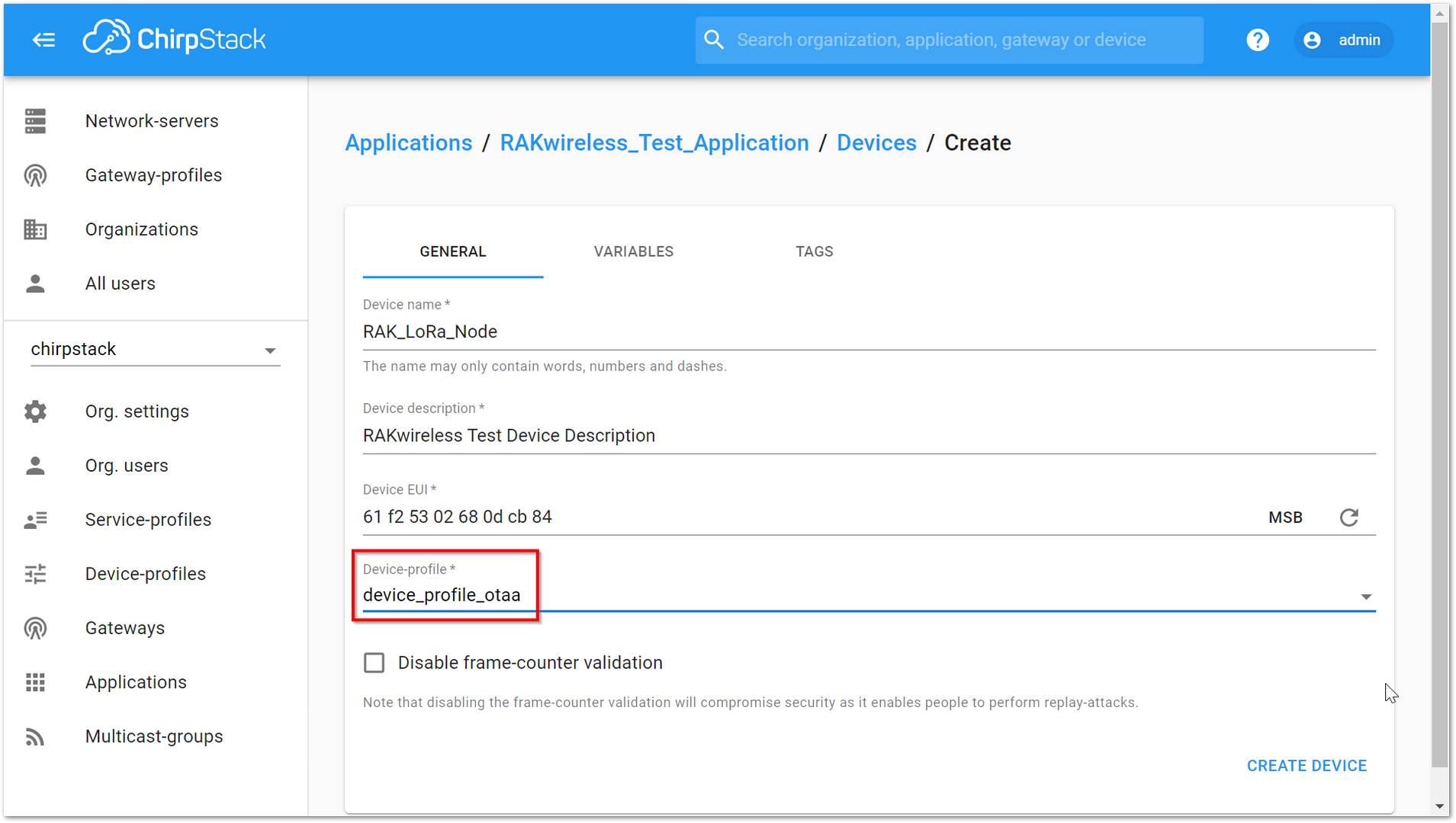 Figure 1: Chirpstack OTAA Activation
- Click “CREATE DEVICE” then generate the application key on this page. You can write it by yourself or generate it automatically by clicking the following icon and pressing “SET DEVICE-KEYS”.
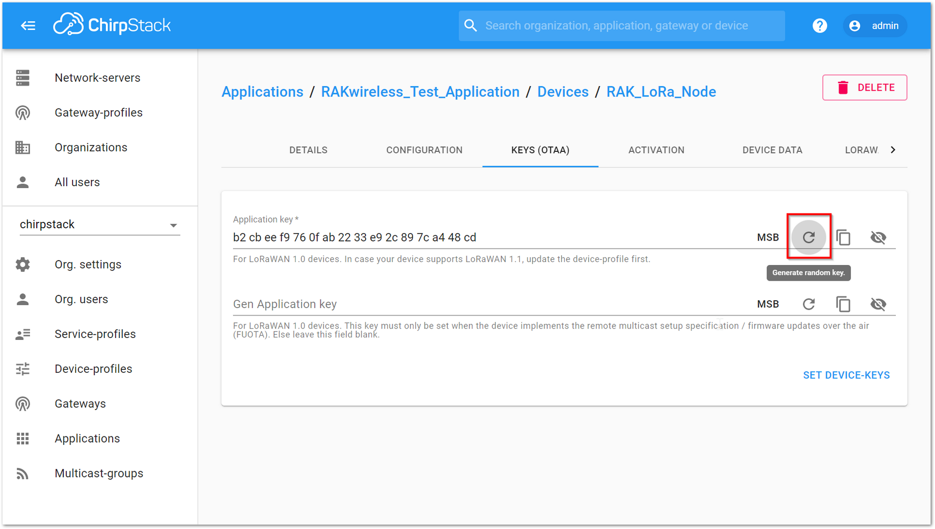 Figure 1: Chirpstack OTAA Set Device Keys
- Set the Device EUI for the RAK4200 Evaluation Board using the "dev_eui".
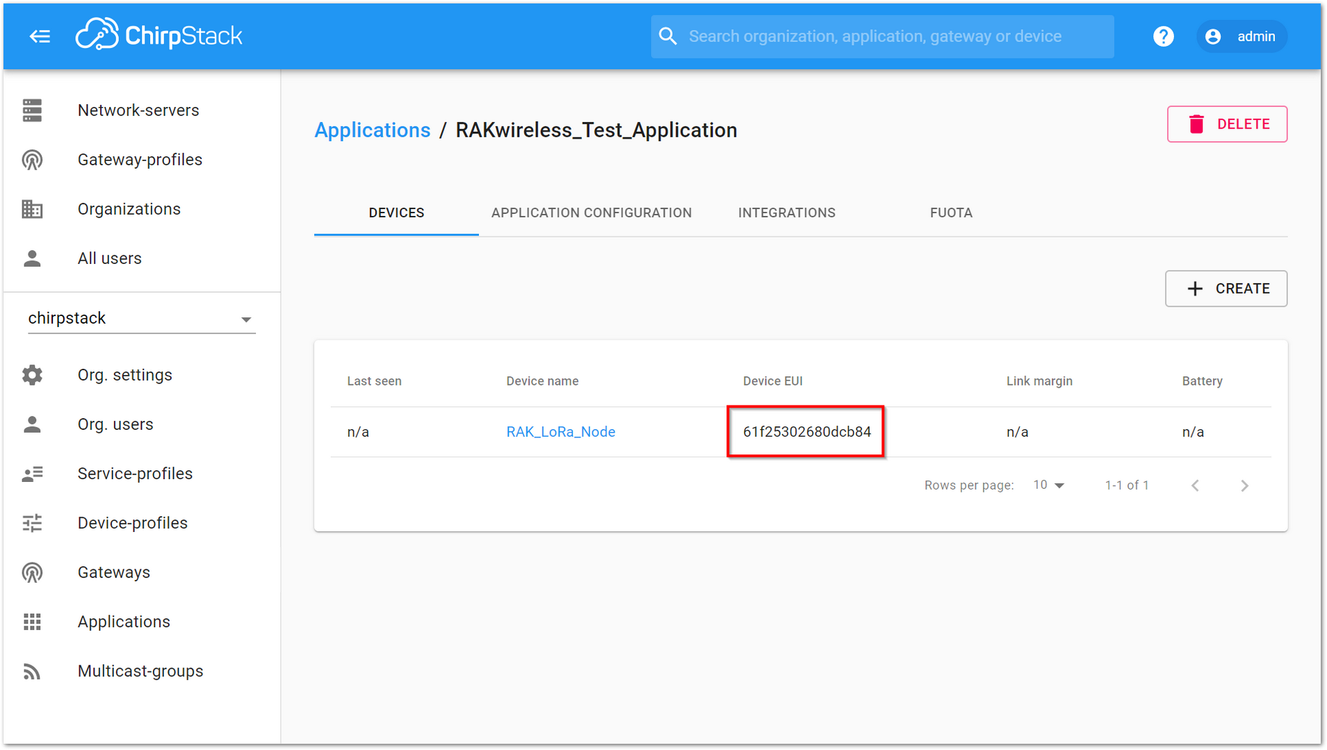 Figure 1: Chirpstack OTAA Set Device EUI
- Set the Application Key for the RAK4200 Evaluation Board using the "app_key".
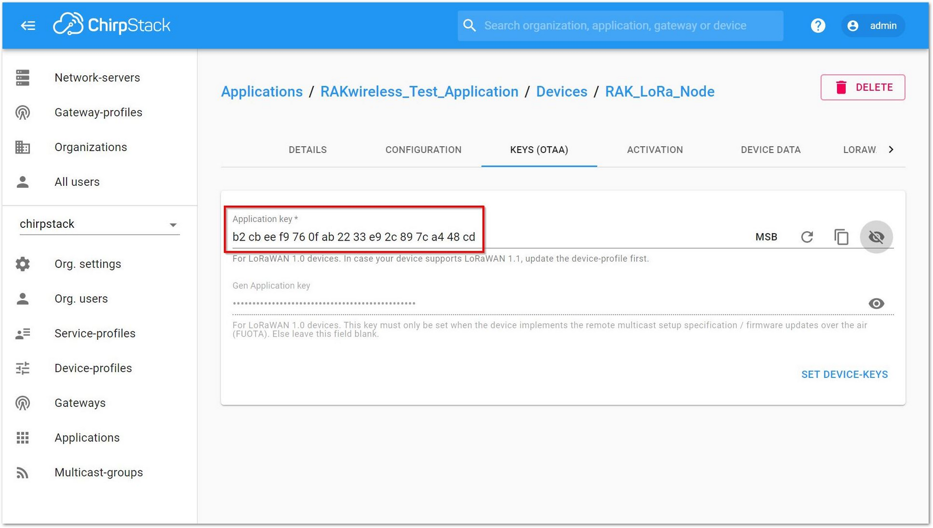 Figure 1: Chirpstack OTAA Set Application Key
The Application EUI which will be set into RAK4200 Evaluation Board as “app_eui” is not necessary for ChirpStack, and you can set it to any value with a correct format.
-
Configure RAK4200 Evaluation Board by using the available commands found in the AT Commands for RAK4200 Evaluation Board. Connect the RAK4200 Evaluation Board to your Windows PC.
-
Power it ON and open RAK Serial Port Tool on your Windows PC as instructed in the Interfacing with RAK4200 Evaluation Board section.
The default settings are as follows:
- Join mode: OTAA
- Class: Class A
- Region: EU868
- If the join mode is not in OTAA, just set the LoRa join mode to OTAA as follows:
at+set_config=lora:join_mode:0
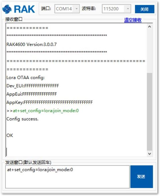 Figure 1: Chirpstack OTAA Join Mode via RAK Serial Port Tool
- Set the LoRa class to Class A:
at+set_config-lora:class:0
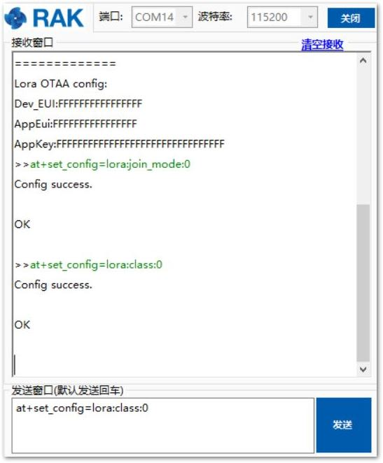 Figure 1: Chirpstack OTAA Set Class via RAK Serial Port Tool
- Set the frequency/region to EU868:
at+set_config=lora:region:EU868
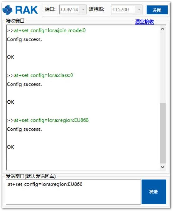 Figure 1: Chirpstack OTAA Set Region/Frequency via RAK Serial Port Tool
- Set the Device EUI:
at+set_config=lora:dev_eui:XXXX
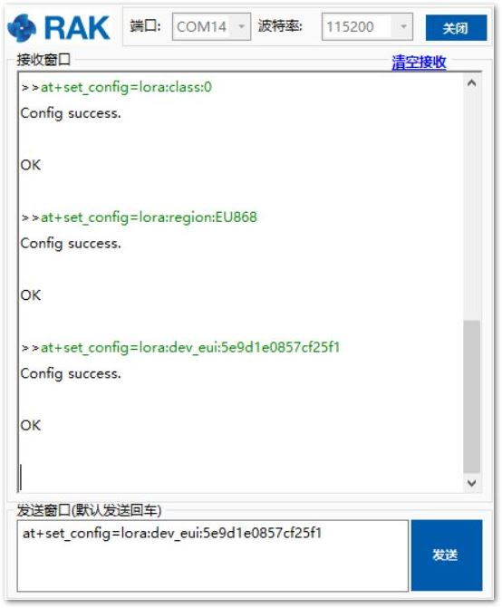 Figure 1: Chirpstack OTAA Set Application EUI via RAK Serial Port Tool
- Set the Application EUI:
at+set_config=lora:app_eui:XXXX
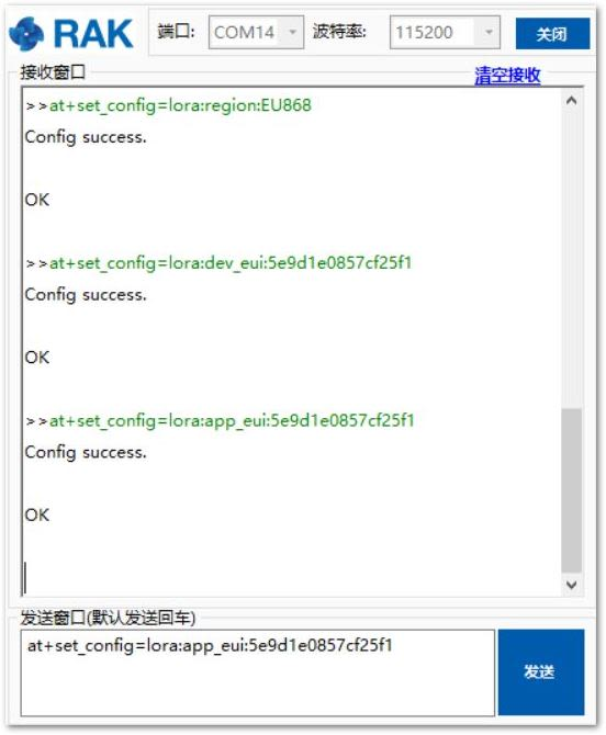 Figure 1: Chirpstack OTAA Set Application EUI via RAK Serial Port Tool
- Set the Application Key:
at+set_config=lora:app_key:XXXX
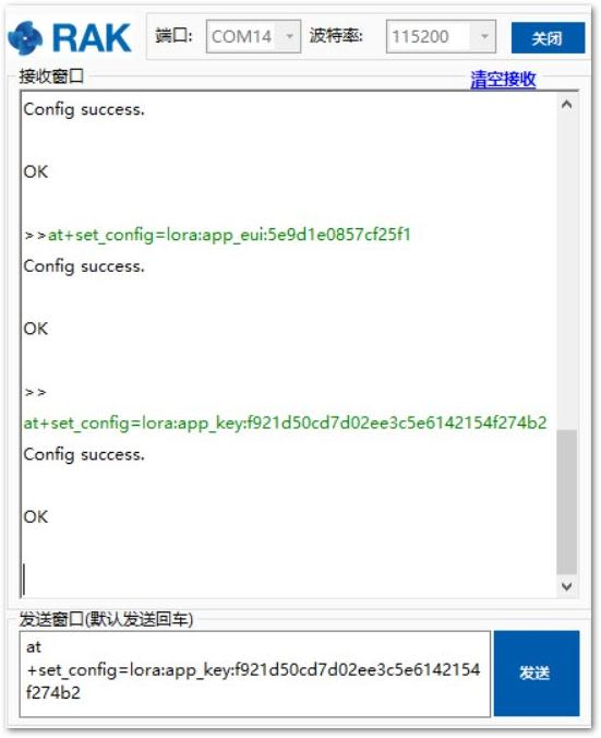 Figure 1: Chirpstack OTAA Set Application Key via RAK Serial Port Tool
After configuring all the parameters, you need to reset the RAK4200 Evaluation Board to save the parameters.
- After reset, send join command:
at+join
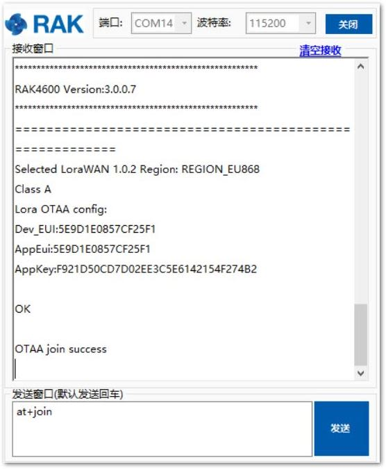 Figure 1: Chirpstack OTAA Join via RAK Serial Port Tool
- You can see the JoinRequest and JoinAccept on the ChirpStack page:
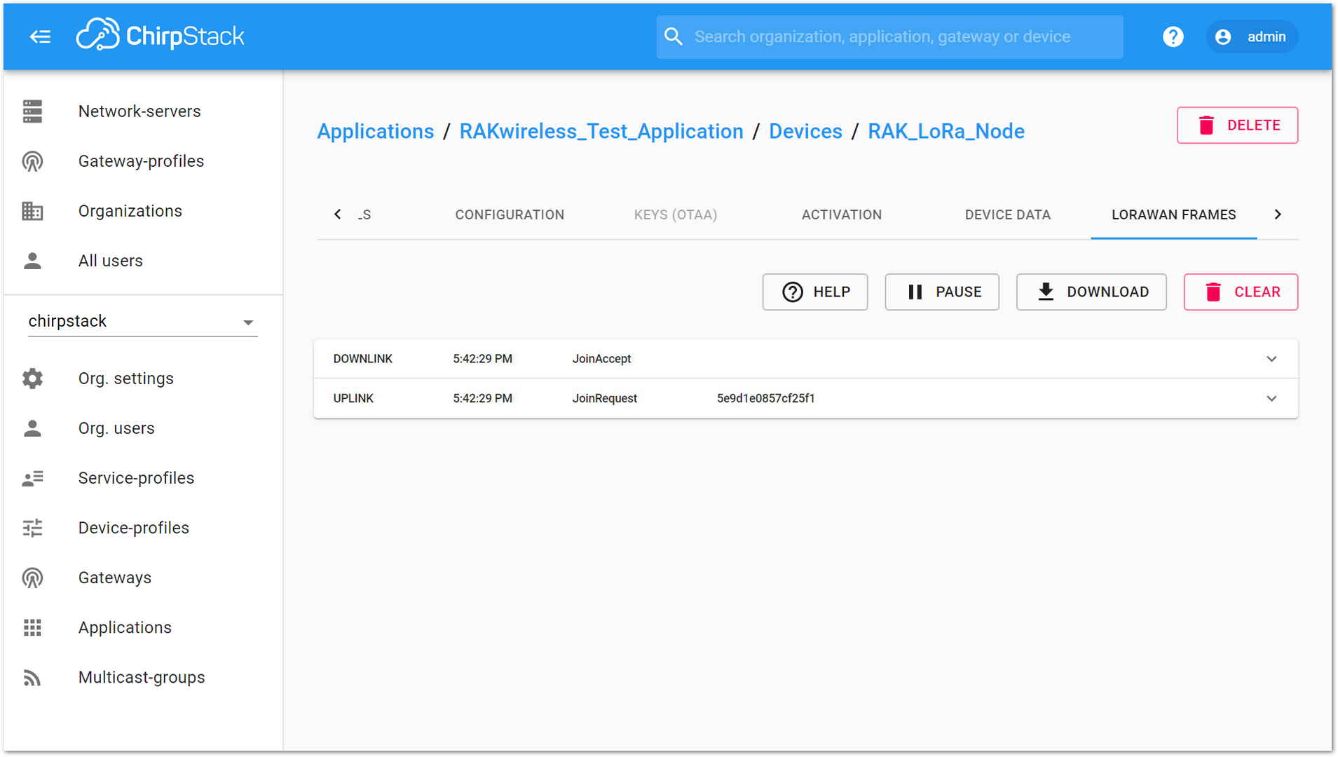 Figure 1: Chirpstack OTAA JoinRequest and JoinAccept
- Try to send data from the RAK4200 Evaluation Board to ChirpStack:
at+send=lora:2:1234567890
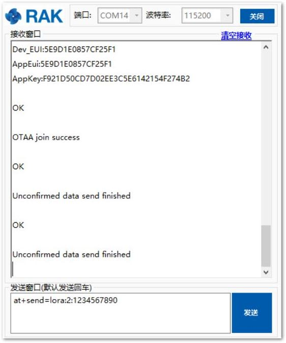 Figure 1: Chirpstack OTAA Sample Data Sent via RAK Serial Port Tool
- You can then see the message on the ChirpStack page the same, as shown in Figure 52.
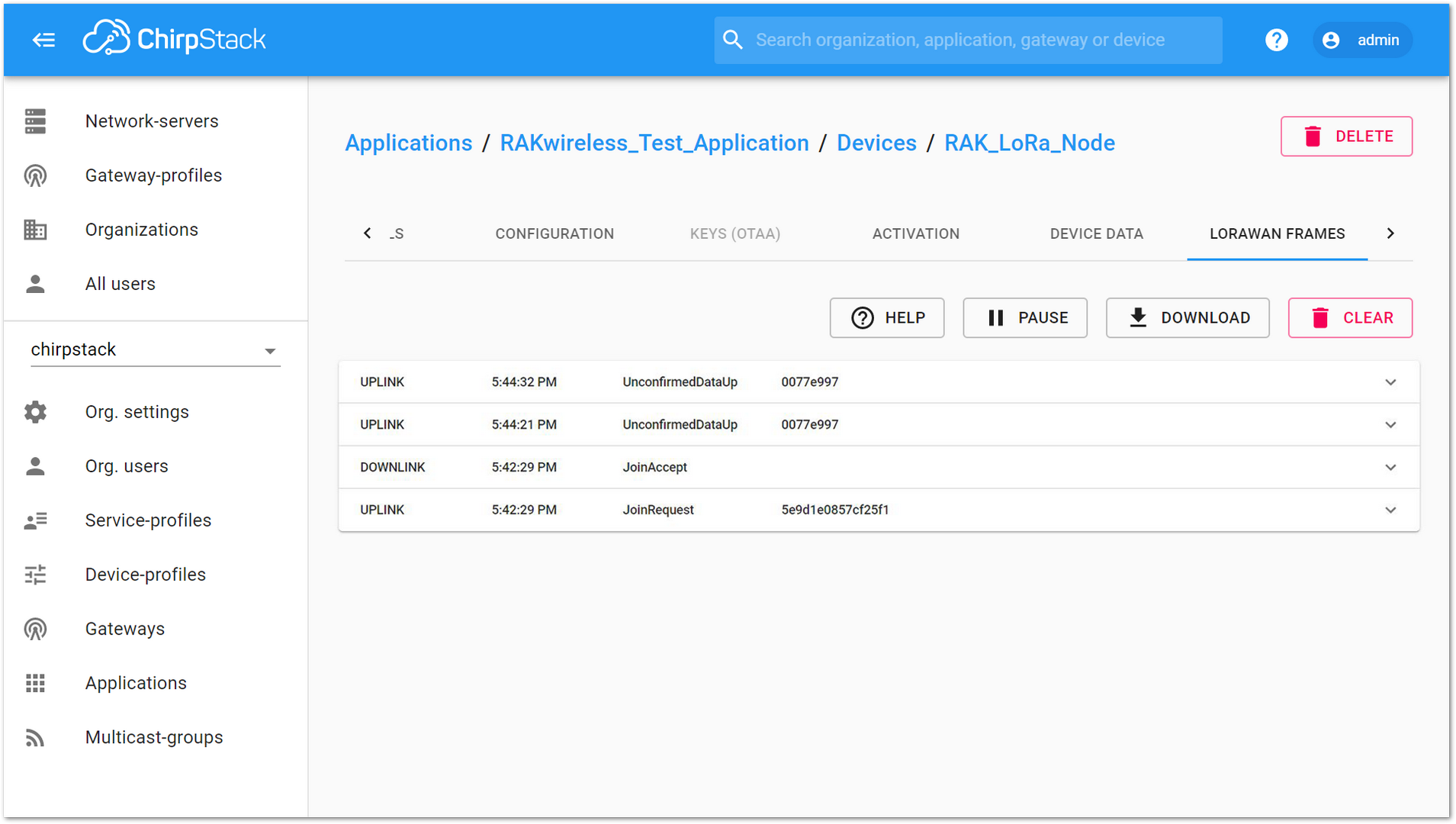 Figure 1: Chirpstack Data Received Preview
ABP Mode
- If you select “DeviceProfile_ABP” or “DeviceProfile_ABP_CN470”, it means you want to join ChirpStack in ABP mode.
The frequency AS923 in ABP Mode is not supported in Chirpstack.
 Figure 1: Chirpstack ABP Activation
- As highlighted in Figure 54, you can see the ABP parameters in the “ACTIVATION” item:
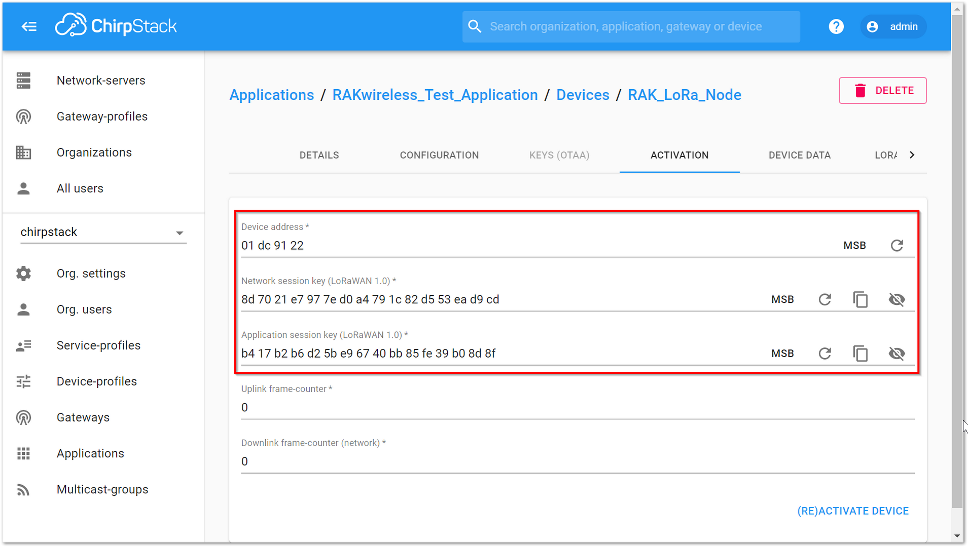 Figure 1: Chirpstack ABP Activation Parameters Needed
- Use these parameters to set the RAK4200 Evaluation Board by using AT command. Set LoRa join mode to ABP:
at+set_config=lora:join_mode:1
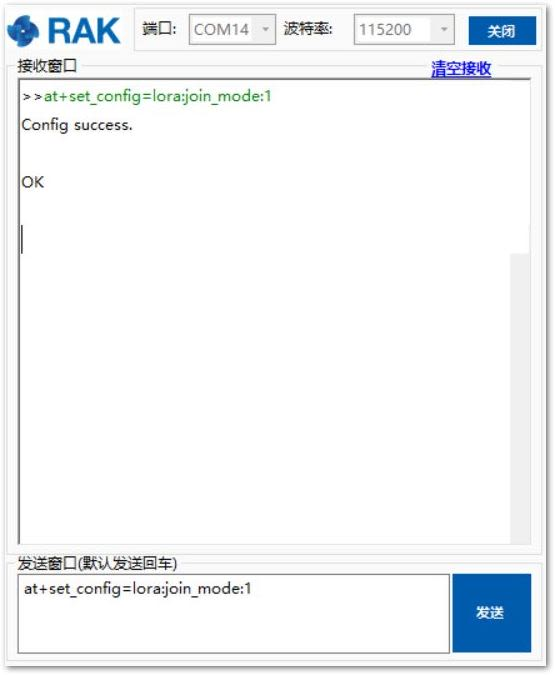 Figure 1: Chirpstack ABP Join Mode via RAK Serial Port Tool
- Set LoRa class to Class A:
at+set_config=lora:class:0
 Figure 1: Chirpstack ABP Set Class via RAK Serial Port Tool
- Set the frequency/region to EU868:
at+set_config=lora:region:EU868
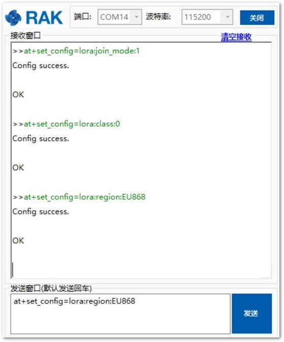 Figure 1: Chirpstack ABP Set Region/Frequency via RAK Serial Port Too
- Set the Device Address:
at+set_config=lora:dev_addr:XXXX
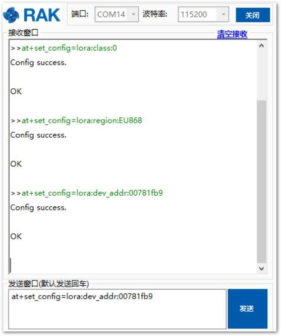 Figure 1: Chirpstack ABP Set Device Address via RAK Serial Port Tool
- Set the Network Session Key:
at+set_config=lora:nwks_key:XXXX
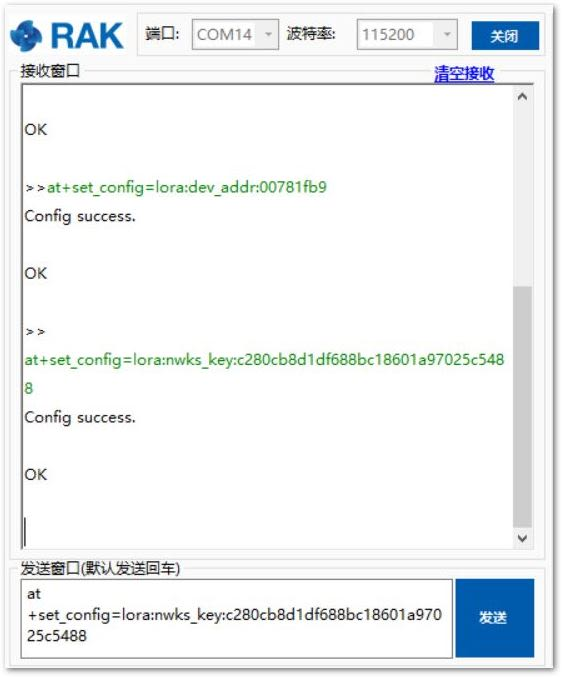 Figure 1: Chirpstack ABP Set Network Session Key via RAK Serial Port Tool
- Set the Application Session Key:
at+set_config=lora:apps_key:XXXX
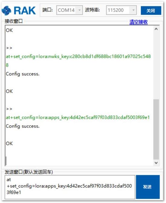 Figure 1: Chirpstack ABP Set Application Session Key via RAK Serial Port Too
After configuring all the parameters, you need to reset the RAK4200 Evaluation Board to save the parameters.
- After resetting the RAK4200 Evaluation Board, join in ABP mode:
at+join
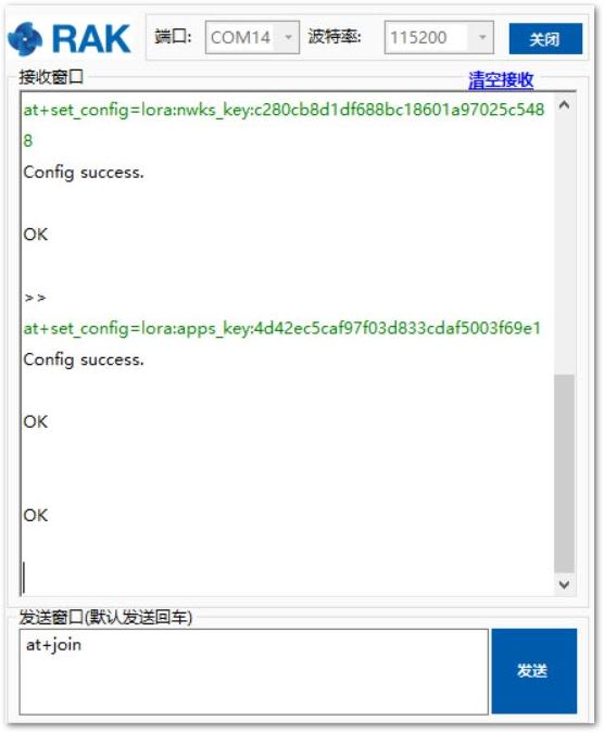 Figure 1: Chirpstack ABP Join via RAK Serial Port Tool
It is not needed to join in ABP mode; but, you still need to set this AT command to validate the parameters which you just set for ABP mode.
- Try to send data from the RAK4200 Evaluation Board to ChirpStack:
at+send=lora:2:123456789
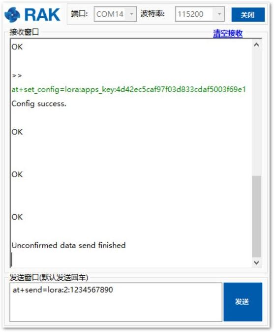 Figure 1: Chirpstack Sample Data Sent via RAK Serial Port Tool
- You can see the data which is just sent from the RAK4200 Evaluation Board on the ChirpStack page:
 Figure 1: Chirpstack Data Received Preview
LoRa P2P Mode
In this section, using P2P on the RAK4200 will be discussed. You will be using EU868 as the frequency; although, it is applicable also to other standard bands.
- First, find two RAK4200 Evaluation Board that can work on EU868 frequency, and make sure their firmware version is not less than V3.0.0.1.
- Next, connect these two RAK4200 Evaluation Board with your Windows PC through UART, and open two serial port tools.
- Now, configure them to both works in LoRa P2P mode as follow:
at+set_config=lora:work_mode:1
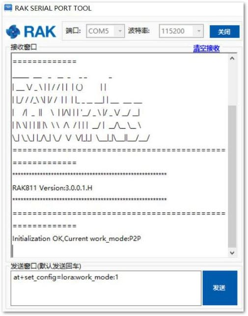 Figure 1: P2P Initialization
- Then configure LoRa P2P parameters for both of them as follow for example:
at+set_config=lorap2p:XXX:Y:Z:A:B:C
Refer to the AT Command Manual to learn about the definition of the parameters used.
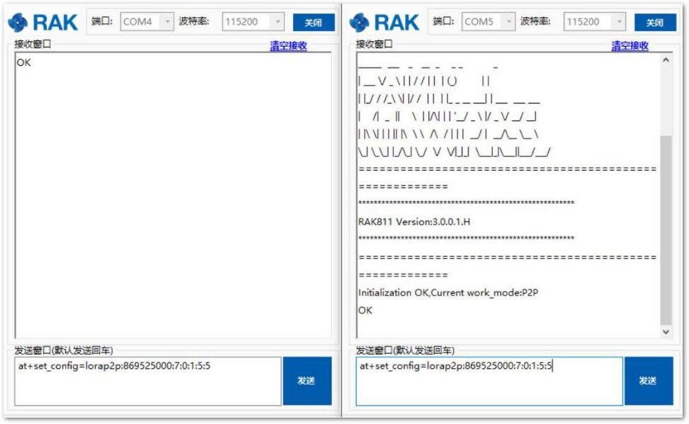 Figure 1: Configuring P2P in both RAK4200 Nodes
- Try to send a message from the first RAK4200 Evaluation Board to the second RAK4200 Evaluation Board.
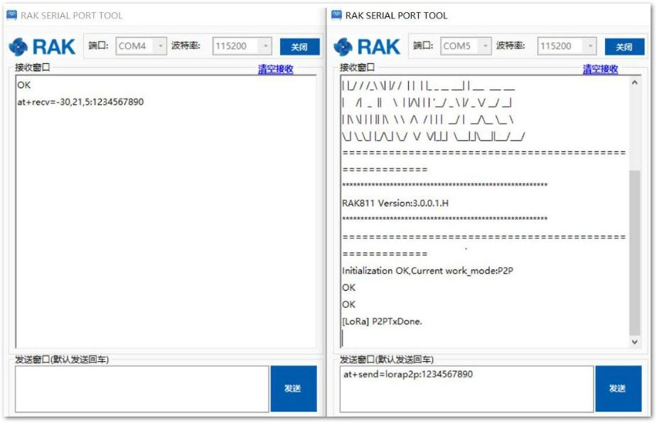 Figure 1: Message sent and received status in the two nodes
- Now, you can send more messages.
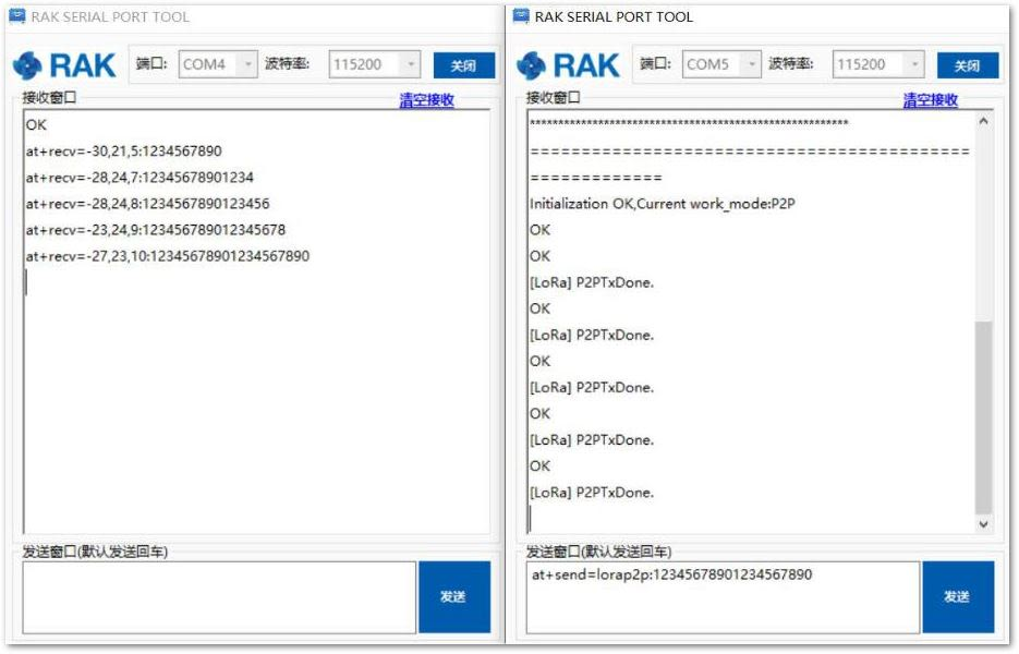 Figure 1: Succeeding Messages sent to the other node
Miscellaneous
RAK5005 Core Module Slot Connection to RAK4201
The RAK5005 is the base board that connects the RAK4200 Core Module. It creates the power supply for the attached module and provides additional IO and Sensor support for your project needs.
RAK4201 is a circuit board module for RAK5005 with a pre-soldered RAK4200 LPWAN Module.
Listed below are the accessible pins and data bus of the attached RAK5005 base board on the RAK4200 EVB:
| RAK4201 Pin Definition | Function Name of WisBase | Pin Number | Pin Number | Function Name of WisBase | RAK4201 Pin Definition |
|---|---|---|---|---|---|
| NC | VBAT | 1 | 2 | VBAT | NC |
| GND | GND | 3 | 4 | GND | GND |
| 3V3 | 3V3 | 5 | 6 | 3V3 | 3V3 |
| NC | USB+ | 7 | 8 | USB- | NC |
| NC | VBUS | 9 | 10 | SW1 | NC |
| UART1_TX/PA9 | TXD0 | 11 | 12 | RXD0 | UART1_RX/PA10 |
| MCU_NRST | RESET | 13 | 14 | LED1 | NC |
| NC | LED2 | 15 | 16 | LED3 | NC |
| 3V3 | VDD | 17 | 18 | VDD | 3V3 |
| I2C_SDA/PB7 | I2C1_SDA | 19 | 20 | I2C1_SCL | I2C_SCL/PB6 |
| UART2_DE/PA1 | AIN0 | 21 | 22 | AIN1 | NC |
| NC | BOOT0 | 23 | 24 | NC | NC |
| NC | SPI_CS | 25 | 26 | SPI_CLK | SPI_CLK/PA5 |
| SPI_MISO/PA6 | SPI_MISO | 27 | 28 | SPI_MOSI | SPI_MOSI/PA7 |
| UART1_DE/PA12 | IO1 | 29 | 30 | IO2 | NC |
| NC | IO3 | 31 | 32 | IO4 | NC |
| UART2_TX/PA2 | TXD1 | 33 | 34 | RXD1 | UART2_RX/PA3 |
| NC | I2C2_SDA | 35 | 36 | I2C2_SCL | NC |
| NC | IO5 | 37 | 38 | IO6 | NC |
| GND | GND | 39 | 40 | GND | GND |
Burning the Bootloader Into the Device
The RAK4200 Evaluation Board bootloader is already pre-installed upon manufacturing, so this bootloader upgrade steps are not necessary. If you find that the bootloader of your RAK4200 Evaluation Board is damaged, contact through the RAKwireless forum.
For RAK4200 modules with firmware version V3.0.0.12 and below, you need to use the STM32CubeProgrammer to upgrade your firmware and upload the .hex file (not the .bin file) of the latest RAK4200 firmware. The lower versions of the firmware have a different bootloader code and will not work on the RAK DFU Tool.
Upgrading the Firmware
The following steps show you how to update the firmware for the RAK4200 WisDuo LPWAN Module connected to the Baseboard:
- Download and install the software needed on your PC.
-
Connect your RAK4200 Evaluation Board in your Windows PC as instructed in the Interfacing with RAK4200 Evaluation Board section.
-
Open the RAK firmware upgrade tool on your Windows PC. Make sure to choose the correct COM Port.
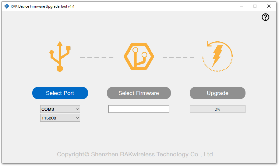 Figure 1: RAK Firmware Upgrade Tool
- Click on the “Select Firmware” button to choose the correct upgrade file:
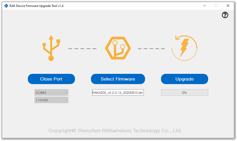 Figure 1: Choosing the Correct Upgrade file
- Click on “Upgrade” to upgrade. This may take a minute.
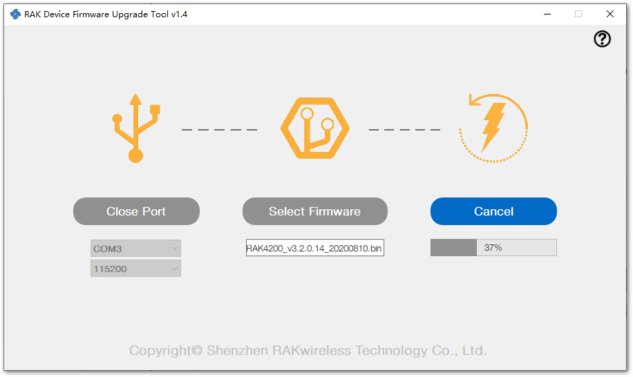 Figure 1: Firmware Upgrading in Process
- If everything went well, you should see the same window, as shown in Figure 72.
 Figure 1: Successfully Upgraded Firmware
-
Close the Firmware Upgrade Tool, and open the RAK Serial Port Tool again.
-
Choose the correct COM port and set the baud rate to 115200. Then open the serial port and enter the AT command shown below to restart:
at+set_config=device:restart
 Figure 1: Restarting your Device
This information means that you have uploaded the Firmware successfully!
Firmware Upgrade Through DAPLink
Refer to RAKDAP1 Flash and Debug Tool.