RAK4200 Module Quick Start Guide
Prerequisites
What Do You Need?
Before going through the step in the installation guide of the RAK4200 WisDuo LPWAN Module, make sure to prepare the necessary items listed below:
Hardware Tools
- RAK4200 WisDuo LPWAN Module
- Windows PC
- USB to TTL adapter
- RAKDAP1 Flash and Debug Tool
Software Tools
- RAK Serial Port Tool
- RAK Device Firmware Upgrade (DFU) Tool
- RAK4200 Firmware
- CH340 Drivers
- RAKDAP1 Flash and Debug Tool
Definition of Terms
List of Acronyms
| Acronym | Meaning |
|---|---|
| ABP | Activation By Personalization |
| BLE | Bluetooth Low Energy |
| DFU | Device Firmware Upgrade |
| EUI | Extender Unique Identifier |
| LoRa | Long Range |
| OTAA | Over The Air Activation |
| TTN | The Things Network |
| P2P | Peer-to-Peer |
Product Configuration
Connecting to the RAK4200 Console
During the configuration of the module through the AT commands, it is possible to read the console output. You can connect to the console of the RAK4200 module through the UART interface.
Connect to the RAK4200
In this document, a RAK4200 module is used for demonstration. Use a USB to TTL adapter to connect to the module. In case the RAK4200 is mounted on an evaluation board or a customized PCB, then use the appropriate interface to connect to the serial port.
- Connect the RAK4200 to a USB to TTL adapter, as shown in Figure 1. Connect the adapter to a USB port of your Windows PC.
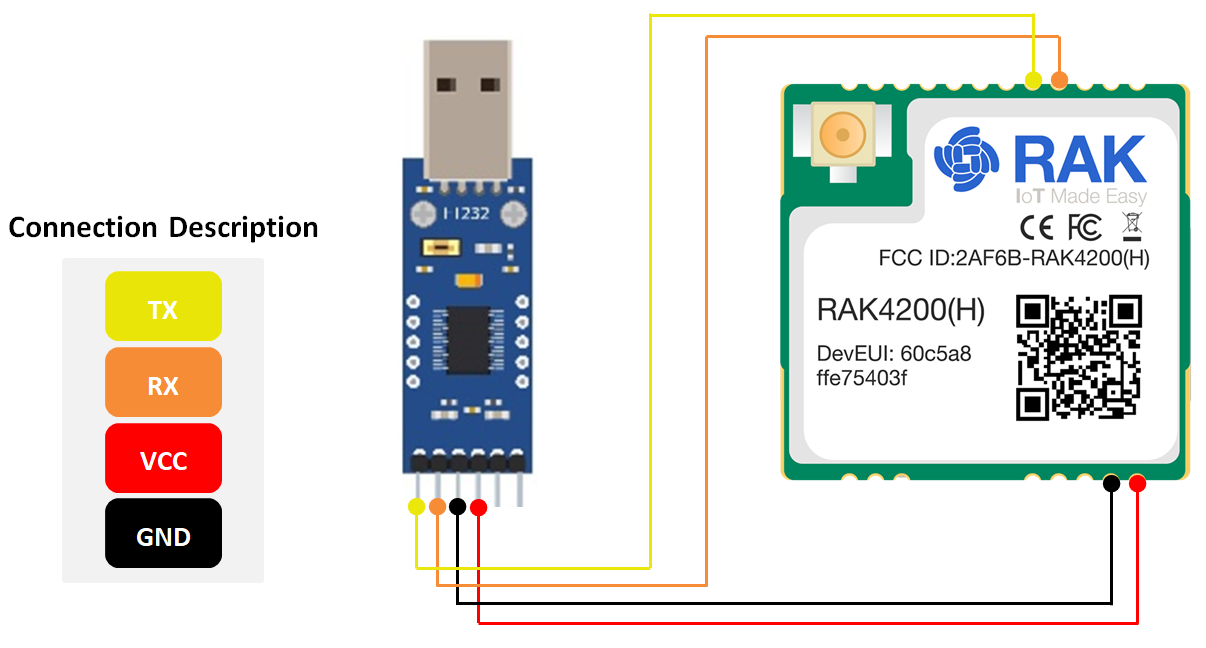 Figure 1: RAK4200 module connection
-
Install a serial communication tool. Any serial communication tool will work, but it is recommended to use the RAK Serial Port Tool.
-
Open the RAK Serial Port Tool.
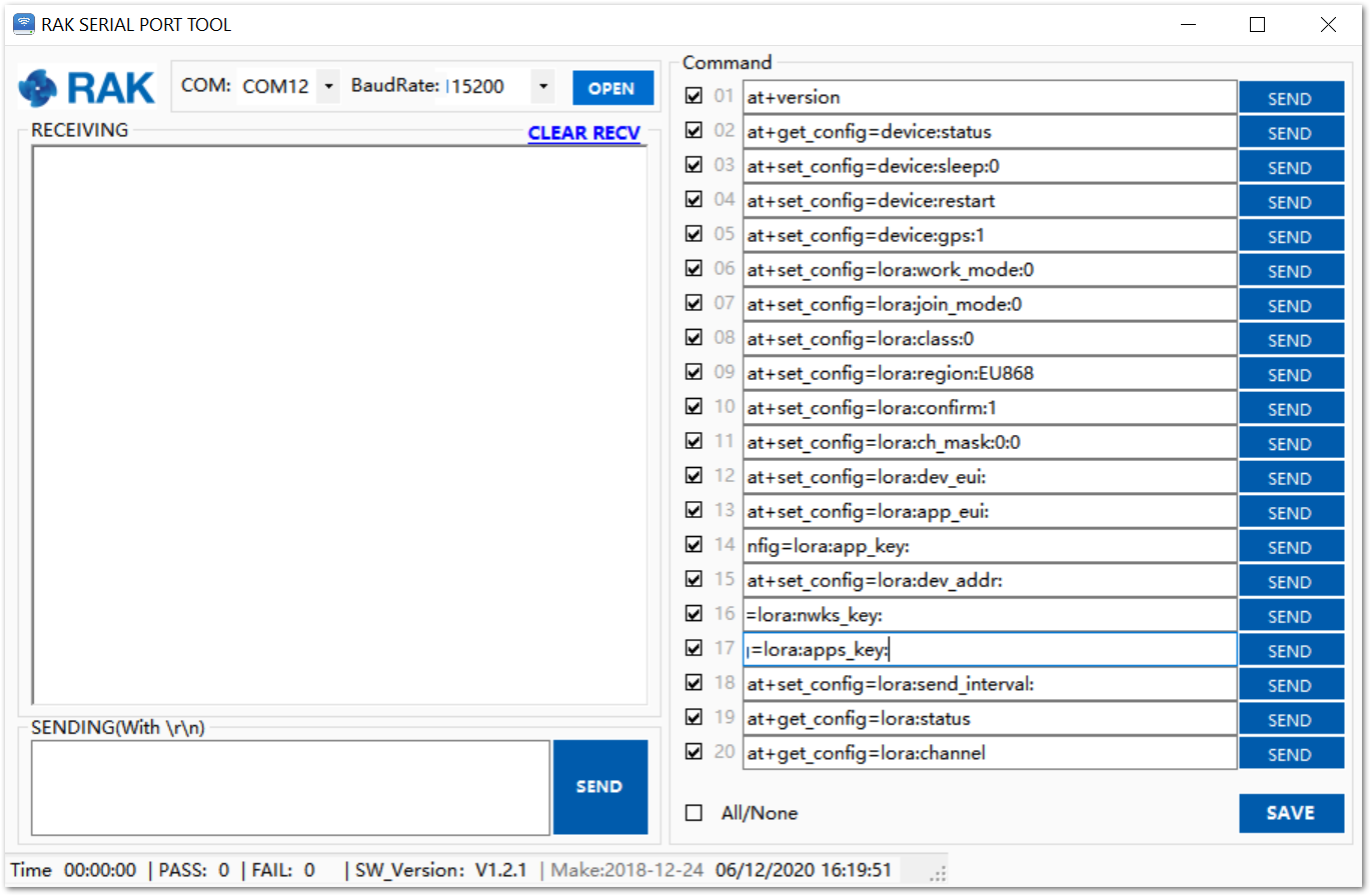 Figure 1: RAK Serial Port Tool
- To find the COM Port number for your device, go to Device Manager by pressing Windows + R and type
devmgmt.msc, or search in the Start Menu. Look for Ports (COM & LPT) and find the name USB-SERIAL CH340. Take note of the COM Port number.
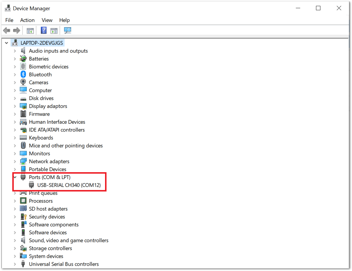 Figure 1: Device Manager
If you didn't find any port with the name USB-Serial CH340, make sure you have installed the CH340 drivers on your Windows PC.
-
Fill in the serial communication parameters: COM Port Number from the Device Manager and Baudrate 115200, then click the “OPEN” button.
-
The RAK4200 console output can now be read in the RAK Serial Port Tool, as shown in Figure 4.
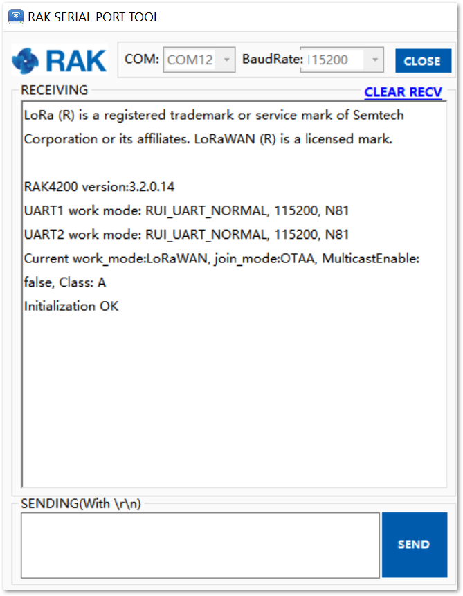 Figure 1: RAK serial port tool connected to RAK4200
Configure RAK4200
To connect the RAK4200 module to a LoRa P2P network or a LoRaWAN network, the module must be configured and LoRa parameters must be set by sending AT commands through the UART interface.
Connect the RAK4200 module to the Windows PC as described in the previous section. Using the Serial communication tool, it is possible to send commands to the RAK4200. For example: Sending the at+version command will display the current firmware version, as shown in Figure 5. For more supported commands, refer to AT Commands for RAK4200.
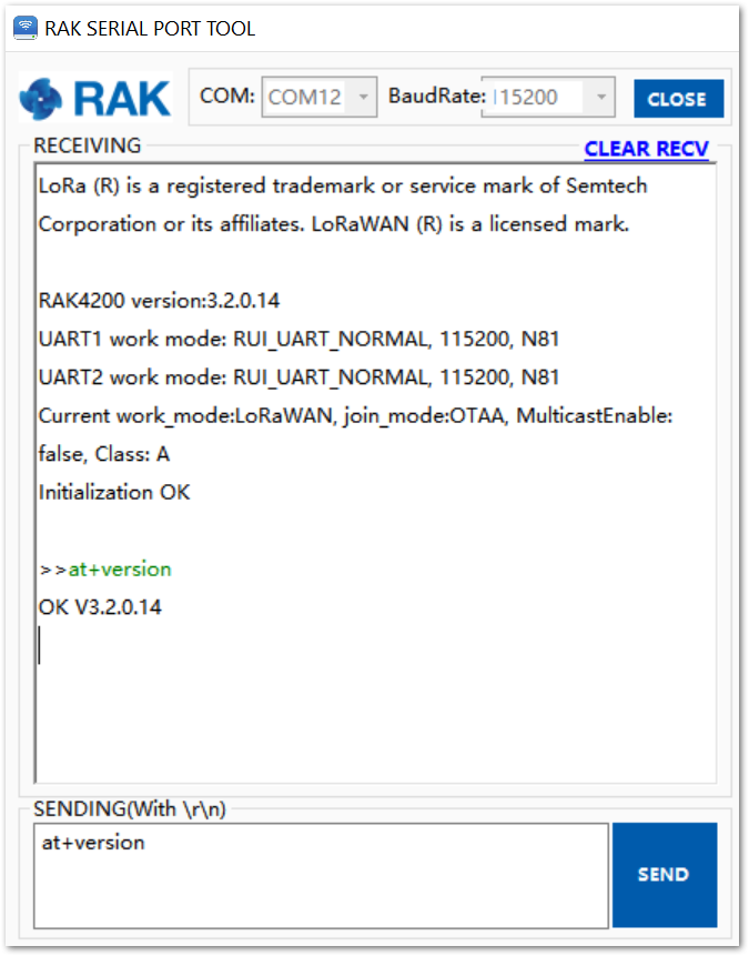 Figure 1: at+version command response
Connecting to The Things Network (TTN)
This section shows how to connect the RAK4200 module to The Things Network (TTN) platform. As described in the TTN’s website: "The engine of The Things Network is our technology - a robust yet flexible and enterprise-ready LoRaWAN network server stack. Our stack caters to the needs of demanding LoRaWAN deployments, from covering the essentials to advanced security configurations and device life cycle management. Backed by SLAs to meet your availability requirements, facilitated by our team of support engineers"
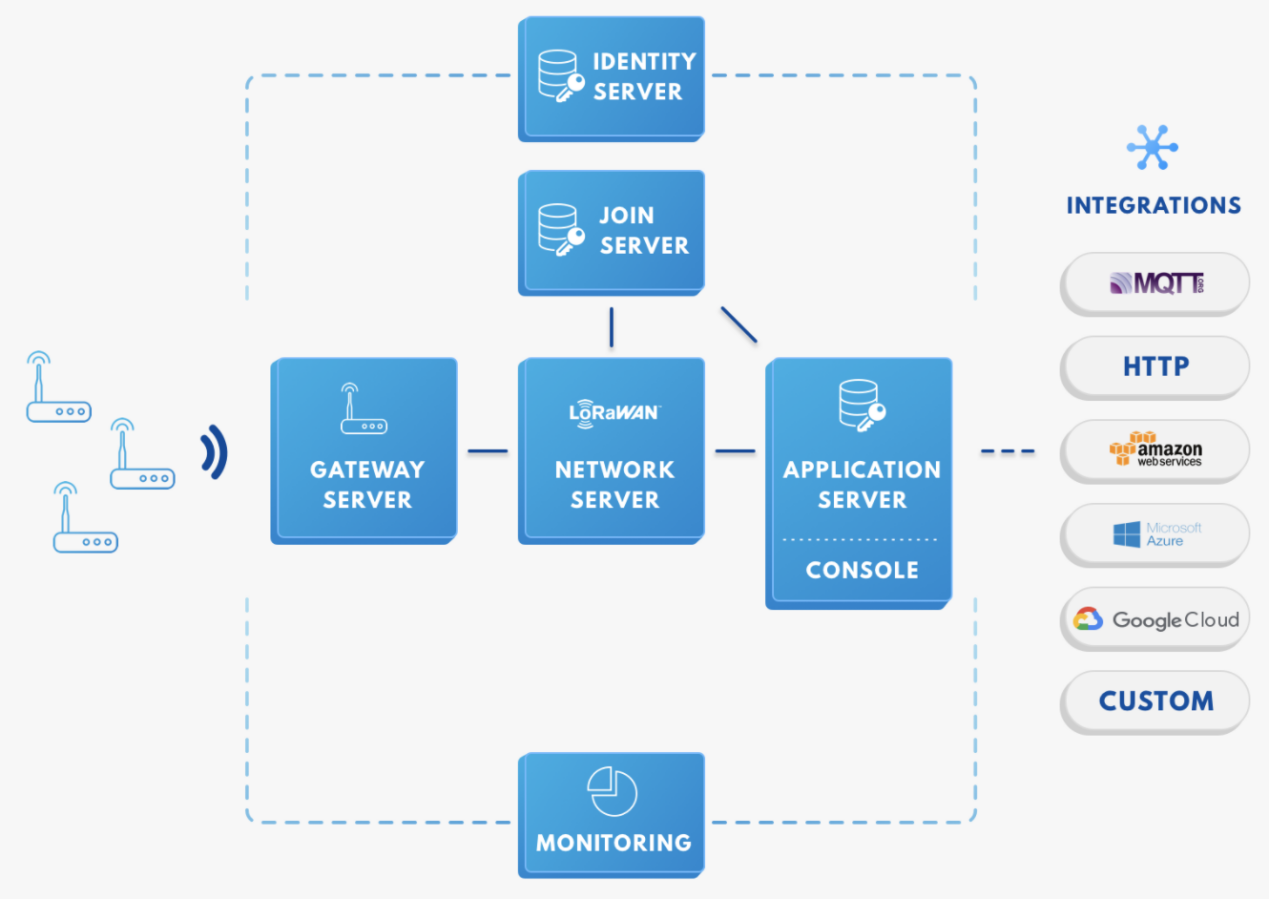 Figure 1: RAK4200 in the context of the TTN
As shown in Figure 6, the RAK4200 module is one of the devices located on the left side. In the context of an IoT solution, the objective is to deploy devices to sense the relevant process variables and transmit the data to the backend servers located in the cloud. The data will be processed and integrated as part of a larger solution that, ultimately, could generate efficiency, traceability, predictability capacity among others.
The RAK4200 module can be part of this ecosystem, and the objective of this section is to demonstrate how simple is to send data to TTN using LoRaWAN. Users must be aware that to achieve this, the RAK4200 must be located inside of coverage of a LoRaWAN gateway.
In summary, these are the requirements:
- Have an account on the TTN website.
- Have access to a LoRaWAN gateway subscribed to the TTN. The frequency band set for the RAK4200 needs to be consistent with the frequency band of the gateway.
- The "RAK Serial Port Tool" provided by RAKWireless.
- The RAK4200 module is connected to a USB to TTL adapter, as shown in Figure 1.
The frequency band used in this example is EU868, which is supported by the high-frequency version of the RAK4200 module.
The steps for sending data to the TTN platform from a RAK4200 module can be summarized as:
- Sign up and log in to the TTN console
- Create a new Application
- Register a new device in the platform
- Configure the Join Mode
- OTAA mode on the platform
- OTAA mode on the RAK4200 module
- ABP mode on the platform
- ABP mode on the RAK4200 module
- Send data from the module and receive it at the platform
In the following sections, each of these steps will be explained in detail. You can choose either to use ABP or OTAA mode to register the device on the network server.
Registering the RAK4200 to TTN
To register the RAK4200 to TTN, execute the following steps:
Login to The Things Network Platform
- Access and login into the TTN, and go to its “Console” section by clicking on the Console icon. You should see an interface similar to Figure 7.
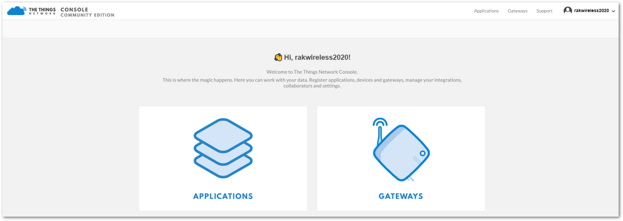 Figure 1: Console Page
Create a New Application
- Choose the “APPLICATIONS” option.
 Figure 1: Application section
- Click on the “add application” link.
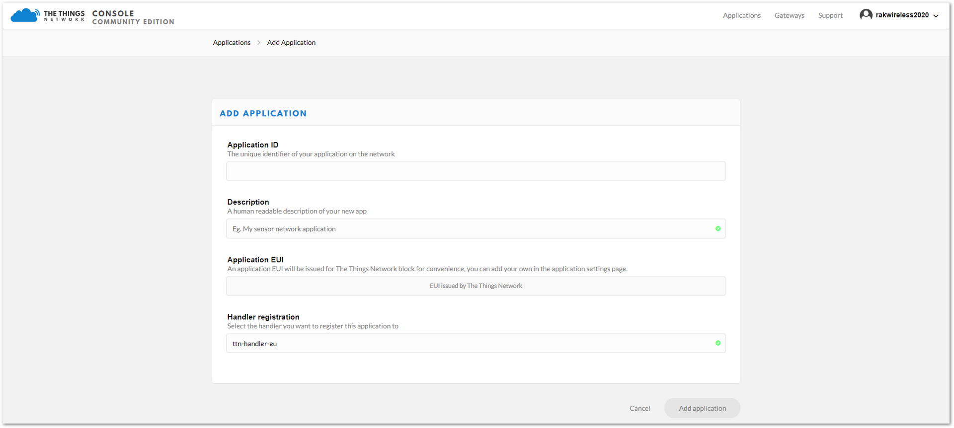 Figure 1: New Application Form
-
Fill in the correct contents in the “Add application form”:
- Application ID: a unique ID on the TTN network that should be in lower case with no spaces
- Description: This is a short and concise human-readable description of your application
- Application EUI: automatically generated by TTN
- Handler Registration: select the handler you want to register this application to
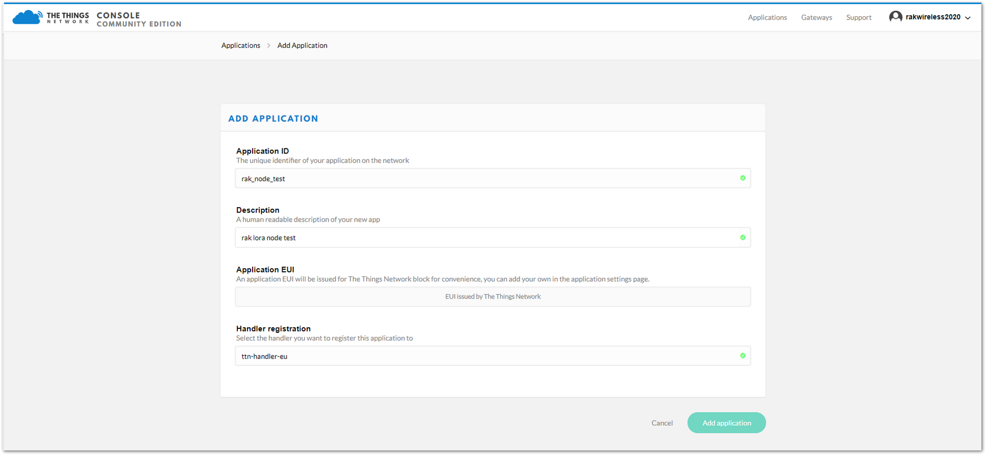 Figure 1: Fill the Add Application Form
- To finish, click on the “Add application” button and a page similar to Figure 11 will appear.
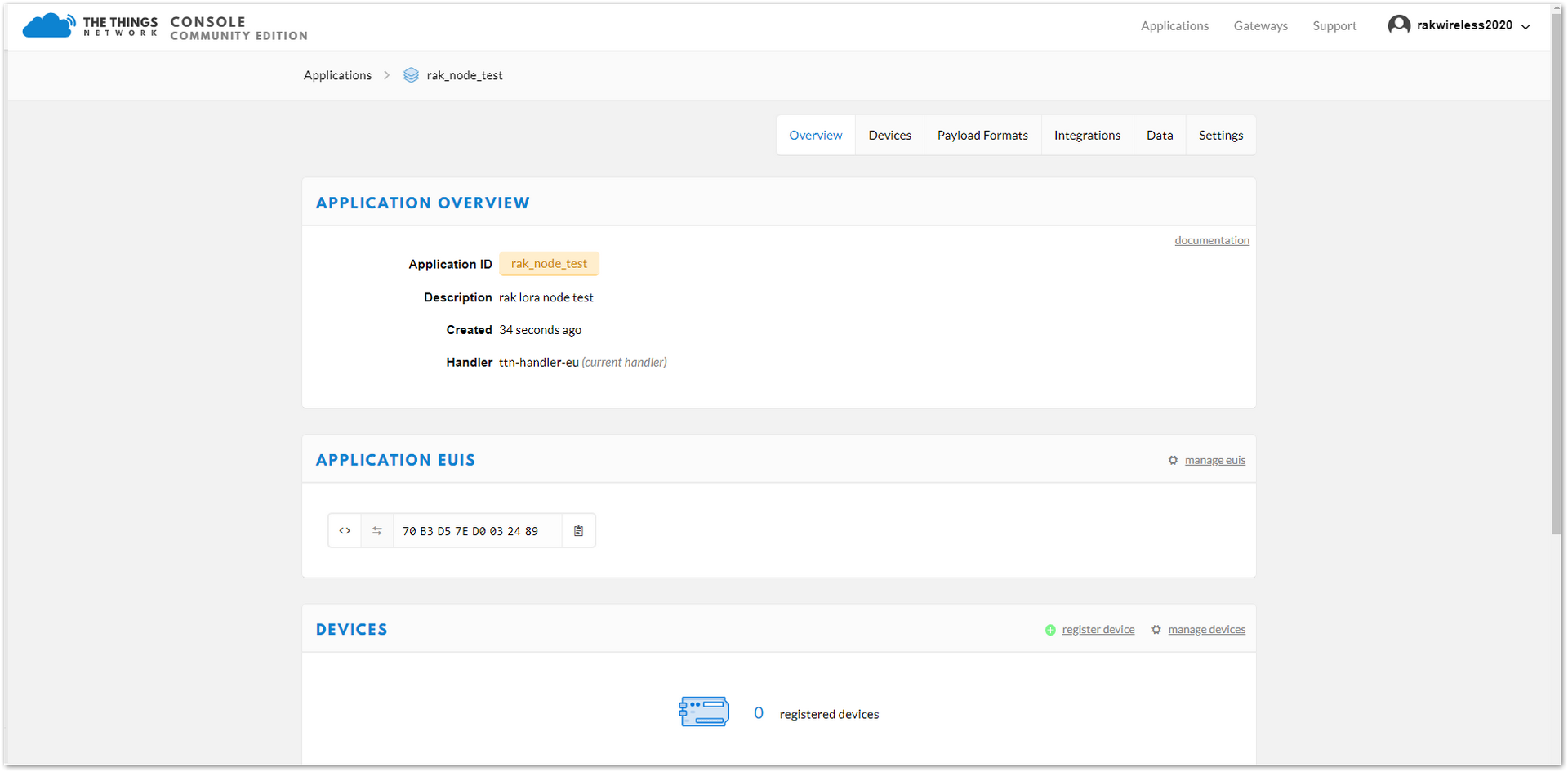 Figure 1: Application Overview
Register a New Device in the Platform
- In the “Application details” page, find the “DEVICES” section by the middle of this page.
 Figure 1: DEVICES section
- Click on the “register device” link, then a “register device form” will appear.
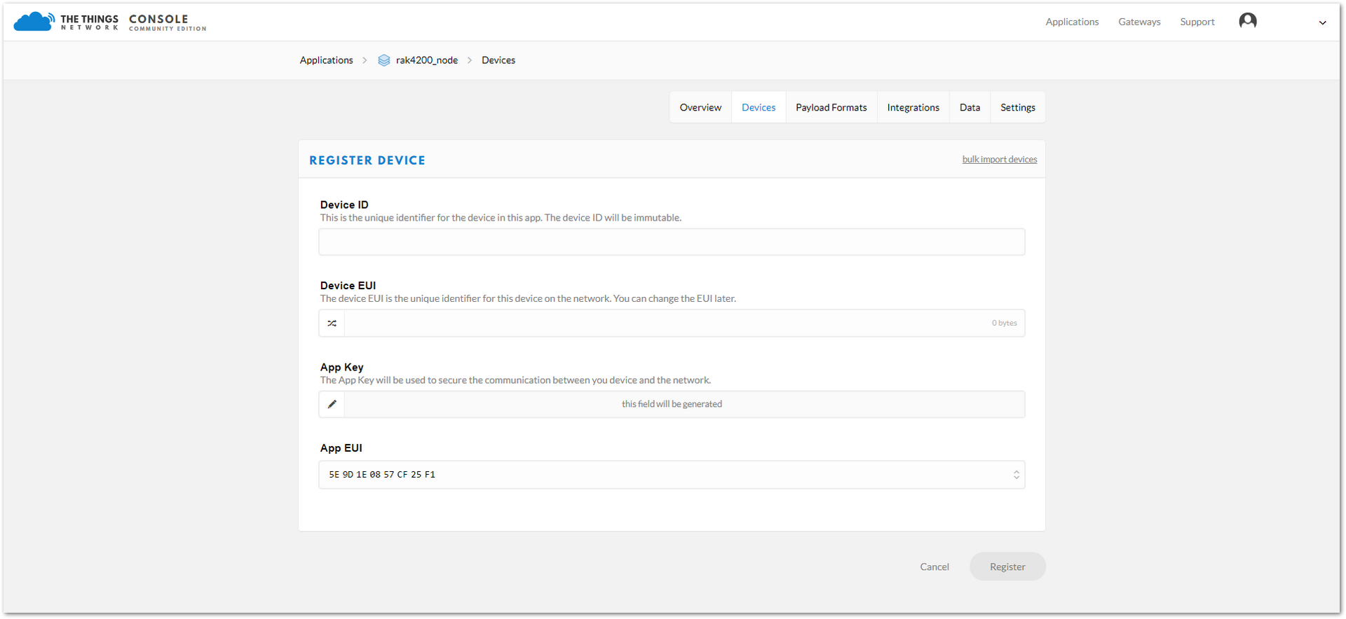 Figure 1: Register a New Device
In this form, the device ID must be unique for the application and must be completed with lower case, alphanumeric characters. The rest of the parameters in the form are very important for the LoRaWAN protocol:
- Device EUI
- Application Key
- Application EUI
The TTN platform can generate these parameters randomly by leaving those fields empty or you can enter already existing values.
- Press the “Register” button to finish the process. The registration results will appear summarized, as shown in Figure 14.
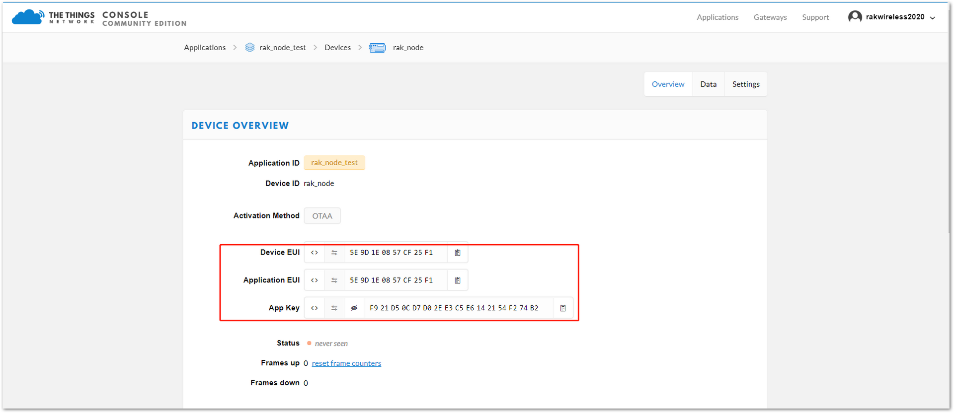 Figure 1: New Device Overview
LoRaWAN Join Mode
The LoRaWAN specification defines that to join in a LoRaWAN network, each end-device has to be personalized and activated. Activation can be done either via Over-The-Air-Activation (OTAA) or via Activation-By-Personalization (ABP). In OTAA, the end-device previously personalized is activated when deployed or reset. In ABP, personalization and activation are done as a single step.
Join in OTAA Mode
Configure the OTAA Mode on the TTN Platform
As shown in Figure 15, the default activation mode in TTN is the OTAA mode. Therefore, no further actions are required on the platform side.
 Figure 1: New Device Parameters
Three parameters from TTN setup are used to configure the RAK4200: “Device EUI”, “Application EUI”, and “App Key”.
Configure the OTAA Mode on the RAK4200 Module
RAK4200 complies with LoRaWAN 1.0.2 specification. By default, the LoRa join mode is OTAA, and the LoRa class is Class A.
To set up the RAK4200 module to join the TTN using OTAA, start by connecting the RAK4200 module to the computer. Open the RAK Serial Port Tool and wait for the communication to start. It is recommended to test the serial communication by sending an AT command as at+get_config=lora:status or at+version.
 Figure 1: RAK Serial Port Tool connected to a RAK4200
As an example, the following parameters will be configured in RAK4200:
- LoRa join mode: OTAA
- LoRa class: Class A
- LoRa region: EU868
- Device EUI: 5e9d1e0857cf25f1 (from TTN registration)
- Application EUI: 5e9d1e0857cf25f1 (from TTN registration)
- Application Key: f921d50cd7d02ee3c5e6142154f274b2 (from TTN registration)
- Set the LoRa join mode to OTAA.
at+set_config=lora:join_mode:0
- Set the LoRa class to Class A.
at+set_config=lora:class:0
- Set the frequency/region.
For the Europe region, type the command:
at+set_config=lora:region:EU868
- Refer to the RAK4200 Datasheet for the list of supported frequencies.
Remember that the device frequency shall be in the same band of the gateway.
- Set the Device EUI.
Get the Device EUI number from TTN registration.
at+set_config=lora:dev_eui:5e9d1e0857cf25f1
- Set the Application EUI.
Get the Application EUI number from the TTN registration.
All zero value Application EUI at+set_config=lora:app_eui:0000000000000000 is not supported and will return error.
at+set_config=lora:app_eui:5e9d1e0857cf25f1
- Set the Application Key.
Get the Application Key from the TTN registration.
at+set_config=lora:app_key:f921d50cd7d02ee3c5e6142154f274b2
- Save the RAK4200 parameters.
Reset the RAK4200 to save the parameters.
Figure 17 summarizes the set of commands sent over the console to set the OTAA mode on the RAK4200.
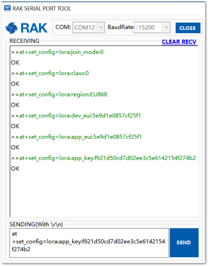 Figure 1: RAK4200 LoRa parameters configuration over the RAK Serial Port Tool
- Finally, send the command to join in OTAA mode.
at+join
- If the request was successfully received by a LoRa gateway, then the “OK Join Success” message will be shown in the console after a few seconds. See Figure 18.
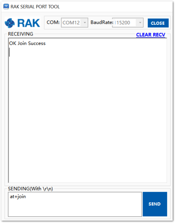 Figure 1: RAK4200 join OTAA mode
- Send data from RAK4200 to TTN.
To send the string 1234567890 over LoRa port 2, type the command:
at+send=lora:2:1234567890
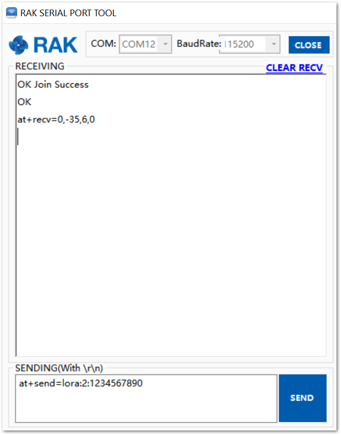 Figure 1: RAK4200 example of sending data to the TTN, in this case, the string 123456890 over port 2
- The data will appear on the TTN console: Applications -> rak_node_test -> Devices -> rak_node -> Data
 Figure 1: TTN console showing the data received from RAK4200
Join in ABP Mode
Configure the ABP Mode on the Platform
As shown previously, the default activation mode in TTN is the OTAA mode. Therefore, no further actions are required on the platform side.
Three parameters from TTN setup are used to configure the RAK4200: “Device EUI”, “Application EUI”, and “App Key”.
For joining TTN in ABP mode, first, you need to change the activation method to ABP. It is done on the TTN console under the “Device Settings” page, as shown in Figure 21.
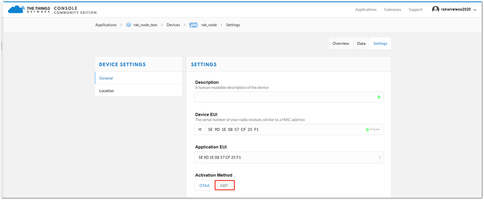 Figure 1: Change the activation mode to ABP
As for the OTAA mode, three TTN parameters will be used to configure the RAK4200 for ABP mode: “Device Address”, “Network Session Key”, and “App Session Key”. These fields can be left empty in the form and TTN will complete them with random values. In other case, you can complete them with specific values.
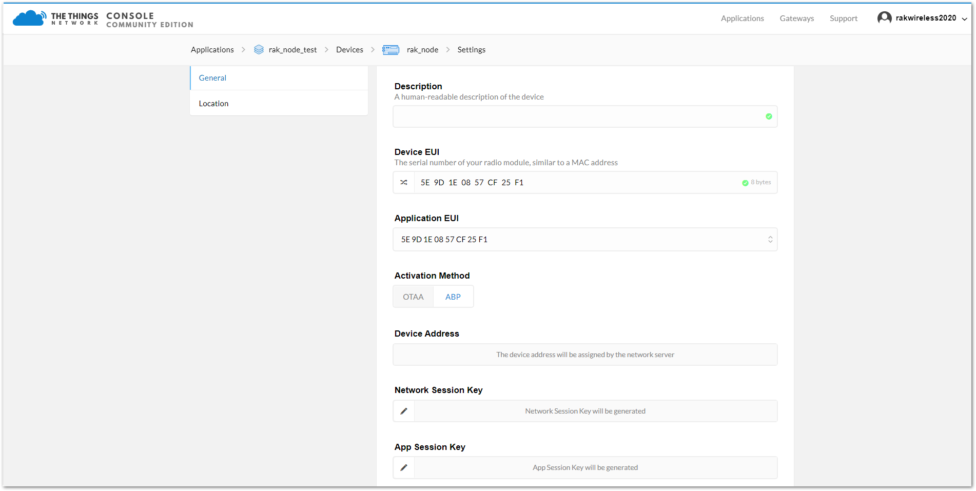 Figure 1: ABP Mode Parameters
After completing the mode change, the device parameters will be summarized on: Applications -> rak_node_test -> Devices -> rak_node. See Figure 23.
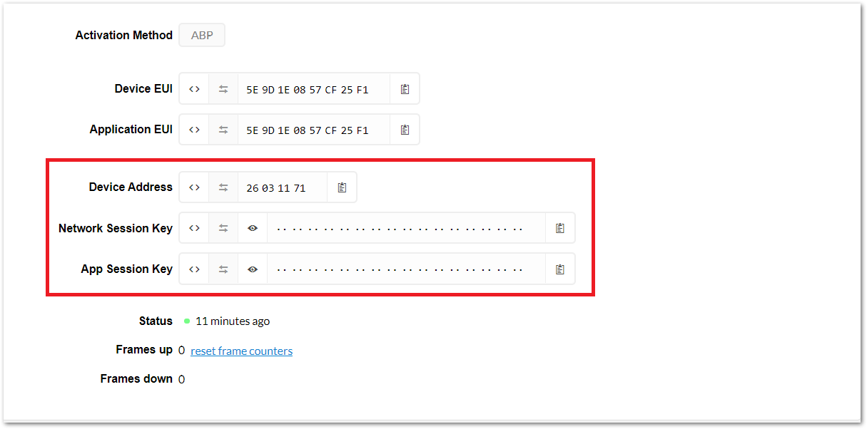 Figure 1: ABP mode configuration finalized
Configure the ABP Mode on the RAK4200 Module
RAK4200 complies with LoRaWAN 1.0.2 specification. By default, the LoRa join mode is OTAA, and the LoRa class is Class A.
To set up the RAK4200 module to join the TTN using ABP, start by connecting the RAK4200 module to the Windows PC. Then open the RAK Serial Port Tool and wait for the communication to start. It is recommended to test the serial communication by sending an AT command as at+get_config=lora:status or at+version.
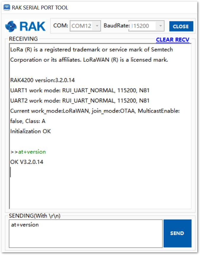 Figure 1: RAK Serial Port Tool connected to a RAK4200
As an example, the following parameters will be configured in RAK4200:
- LoRa join mode: ABP
- LoRa class: Class A
- LoRa region: EU868
- Device address: 26031171 (from TTN registration)
- Network Session Key: c280cb8d1df688bc18601a97025c5488 (from TTN registration)
- Application Session Key: 4d42ec5caf97f03d833cdaf5003f69e1(from TTN registration)
- Set LoRa join mode to ABP.
at+set_config=lora:join_mode:1
- Set the LoRa class to Class A.
at+set_config=lora:class:0
- Set the Frequency/Region.
For the Europe region, type the command:
at+set_config=lora:region:EU868
- Refer to the RAK4200 Datasheet for the list of supported frequencies.
Remember that the device frequency shall be in the same band of the gateway.
- Set the Device Address.
Get the Device Address from TTN registration.
at+set_config=lora:dev_addr:26031171
- Set the Network Session Key.
Get the Network Session Key from the TTN registration.
at+set_config=lora:nwks_key:c280cb8d1df688bc18601a97025c5488
- Set the Application Key.
Get the Application Key from the TTN registration.
at+set_config=lora:apps_key: 4d42ec5caf97f03d833cdaf5003f69e1
- Save the RAK4200 parameters.
Reset the RAK4200 to save the parameters. Figure 25 summarizes the set of commands sent over the console for setting the OTAA mode on the RAK4200.
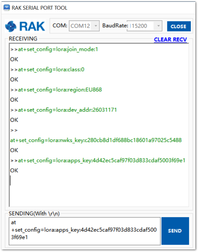 Figure 1: RAK4200 LoRa parameters configuration over the Serial Port Tool
- Send the command to join in ABP mode.
at+join
The ABP mode in LoRaWAN does not require to join a network before sending a LoRaWAN package. But to keep the consistency of the internal states of the firmware of the RAK4200 module, it is still required to send the at+join command in the ABP mode.
Right after sending the command, the “OK Join Success” should be replied to in the console the same, as shown in Figure 25.
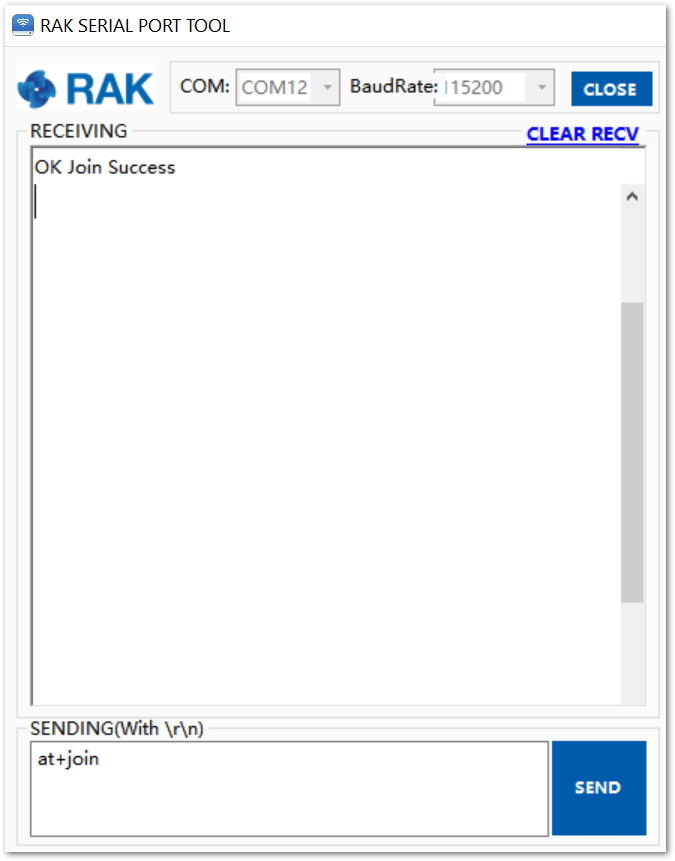 Figure 1: RAK Serial port tool join LoRaWAN in ABP mode
- Send data from RAK4200 to ChirpStack.
To send the string 1234567890 over LoRa port 2, type the command:
at+send=lora:2:1234567890
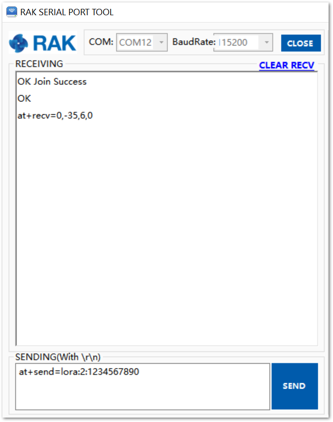 Figure 1: RAK Serial Port Tool, sending a message in ABP mode
- The data will appear on the TTN console: Applications -> rak_node_test -> Devices -> rak_node -> Data.
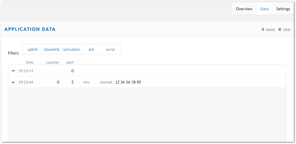 Figure 1: TTN console with received data from RAK4200
Connecting with ChirpStack
This section shows how to connect the RAK4200 module to the ChirpStack platform. As described on ChirpStack’s website:
“The ChirpStack open-source LoRaWAN Network Server stack provides open-source components for LoRaWAN networks. Together they form a ready-to-use solution including a user-friendly web interface for device management and APIs for integration.
The modular architecture makes it possible to integrate within existing infrastructures. All components are licensed under the MIT license and can be used for commercial purposes.”
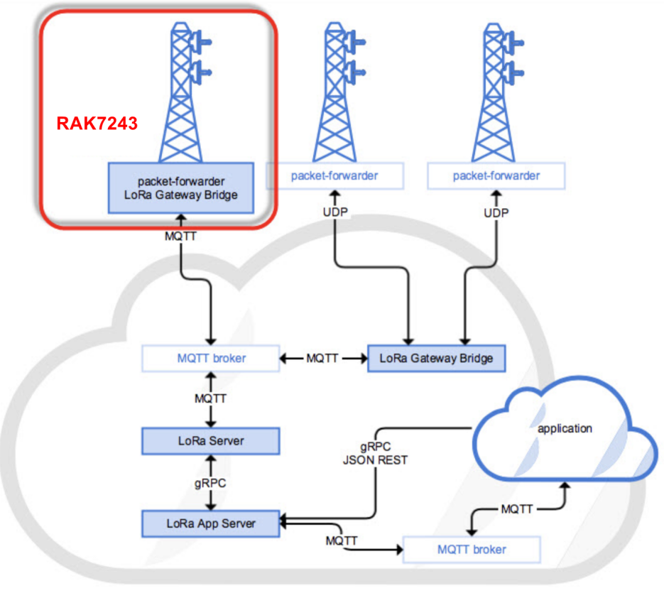 Figure 1: RAK4200 module in the context of the ChirpStack platform
The architecture of the ChirpStack platform is shown in Figure 28. Similar to the case of TTN, the RAK4200 module is located in the periphery and will transmit the data to the backend servers through a LoRa gateway. For more information about this architecture, refer to Chirpstack website.
In this section, it is assumed that you are using a RAK LoRa gateway, such as RAK7243. The gateway must be configured to ChirpStack deployment. More information about that can be found at Connect the Gateway with Chirpstack.
You can also check the other RAK gateways RAK WisGate products.
The frequency band used in this example is EU868, which is supported by the high-frequency version of RAK4200.
And these are the steps to send data to the ChirpStack platform from a RAK4200 module:
- Create a new Application
- Register a new device on the platform
- Configure the Join Mode:
- OTAA mode on the platform
- OTAA mode on the RAK4200 module
- ABP mode on the platform
- ABP mode on the RAK4200 module
- Send data from the module and receive it at the platform
The following section gives the details of each of these aforementioned steps. As usual, you can either choose to use ABP or OTAA mode to register the device to the network server.
Create a New Application
- Go to the “Applications” section, as shown in Figure 30.
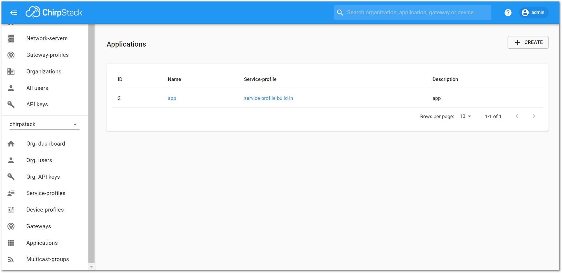 Figure 1: Applications section of the RAK’s ChirpStack LoRaServer
- By default, a new Application should be created, although it is possible to reuse the existing ones. For this setup, create a new Application by clicking on the “+ CREATE” button and filling in the required parameters, as shown in Figure 31 and Figure 32.
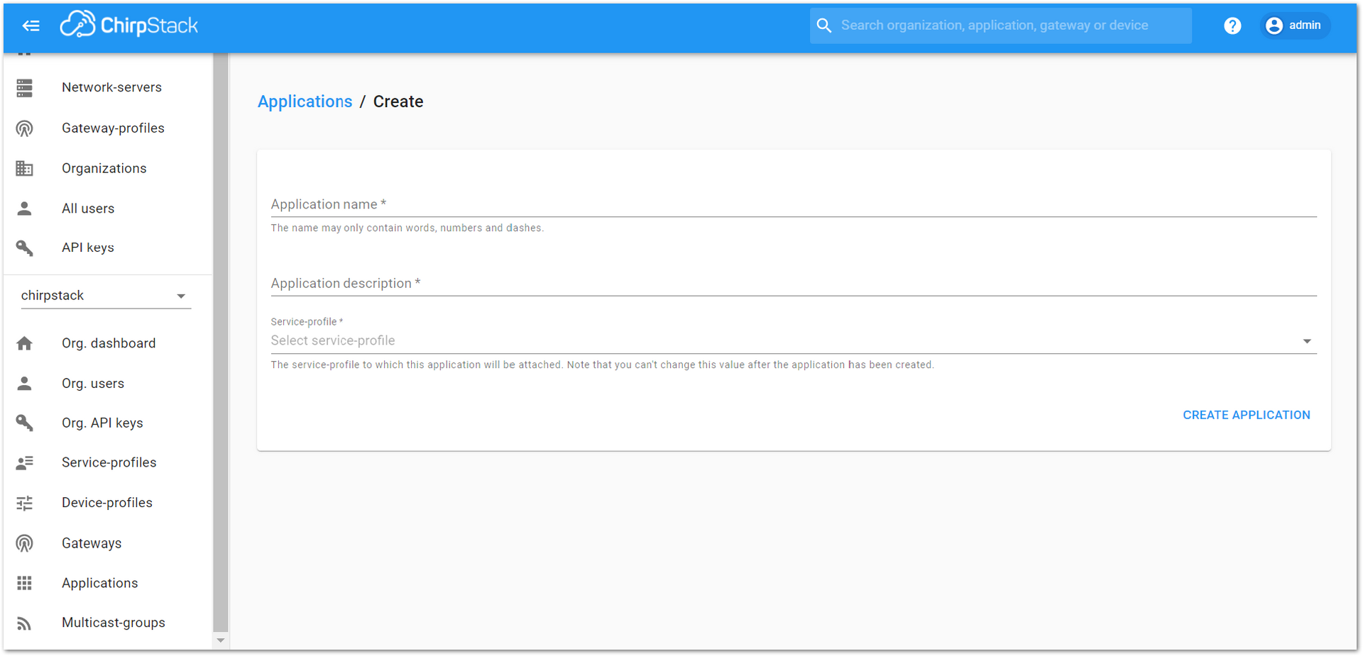 Figure 1: Creating a new Application
-
For this setup, create an Application named “rak_node_test”. Fill in the required parameters, as shown in Figure 32.
-
To finish, click on the “CREATE APPLICATION” button.
ChirpStack LoRaServer supports multiple system configurations, with only one by default.
- Application Name: rak_node_test
- Application Description: test
- Service-profile: Select the system profile. Choose service-profile-built-in
The Application Description field is just a descriptive text.
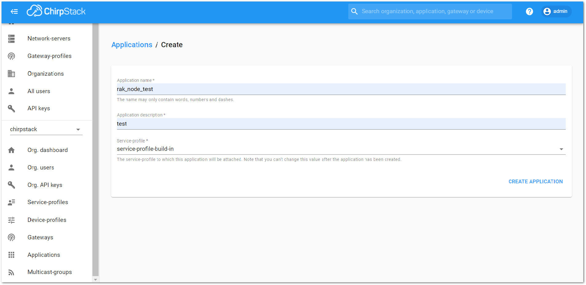 Figure 1: Filling the Application Parameters
Register a New Device in the Platform
- Choose the Application created in the previous step, then select the “DEVICES” tab, as shown in Figure 33 and Figure 34.
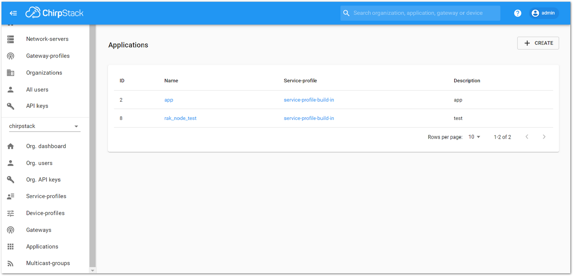 Figure 1: List of applications created
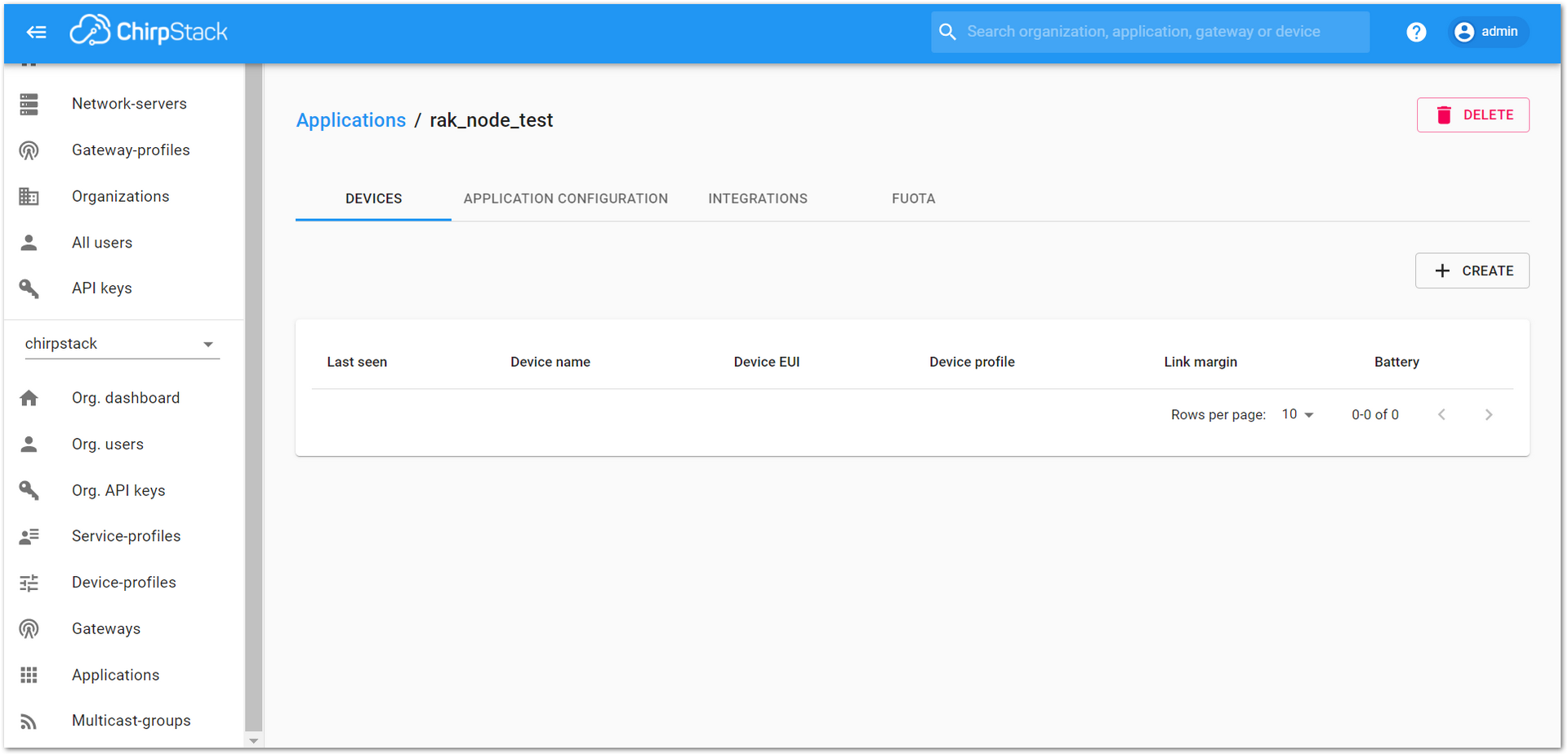 Figure 1: Device tab of an Application
- Once inside of the “DEVICES” tab, create a new device (LoRa node) by clicking on the “+ CREATE” button.
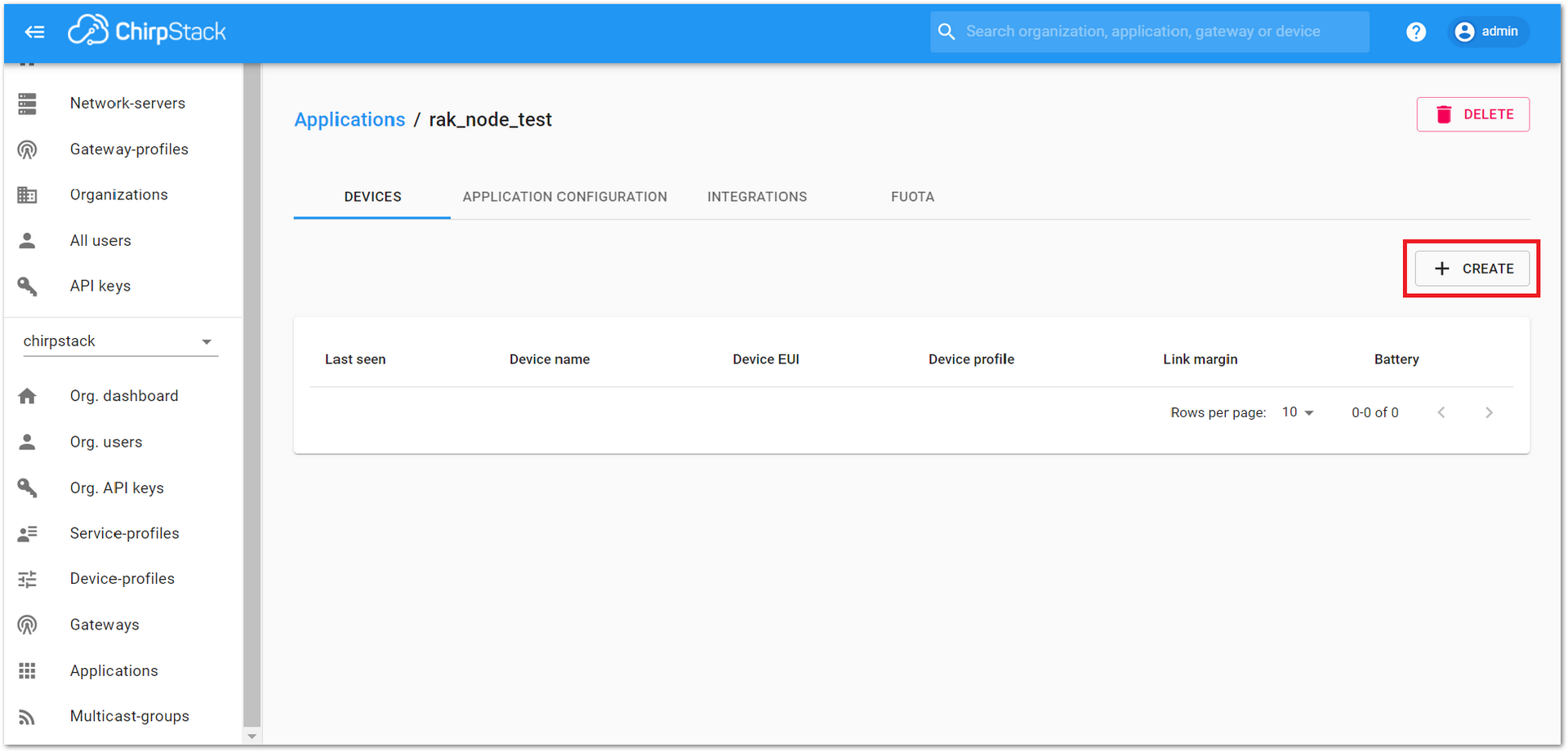 Figure 1: Add a new device at the Devices tab
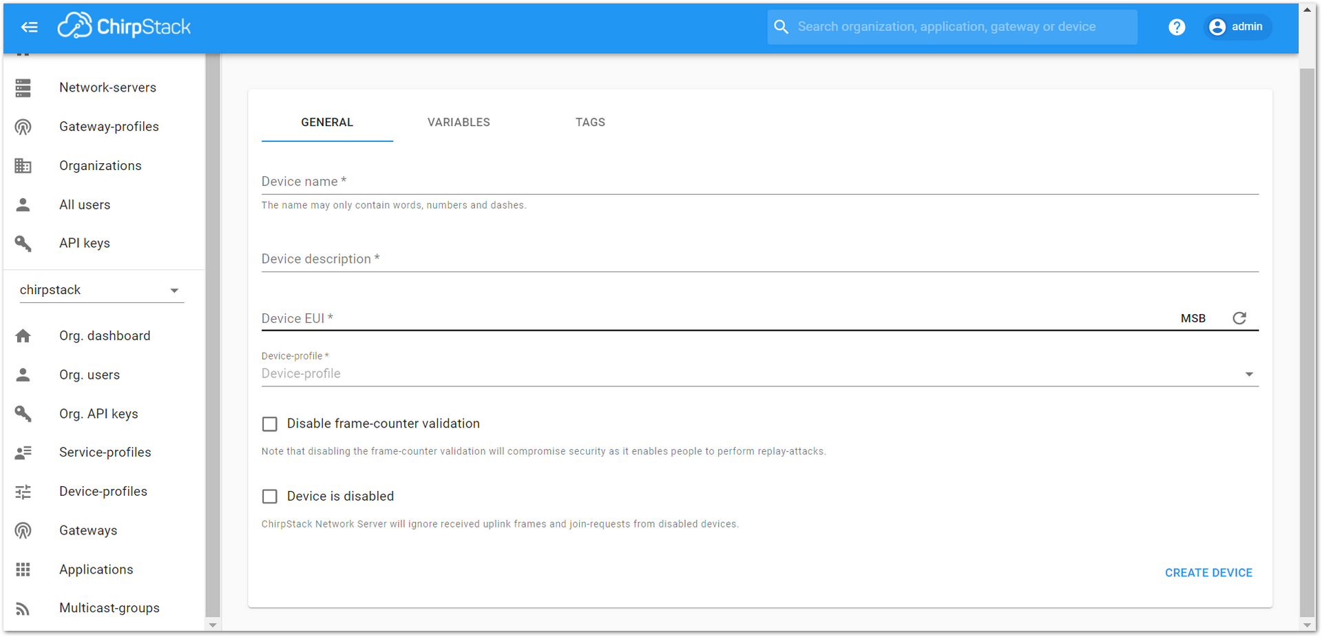 Figure 1: New device registration form
- Fill in the parameters requested as appears in Figure 37:
- Device name and Device description: These are just descriptive texts.
- Device EUI: This interface allows you to generate a Device EUI automatically by clicking the icon highlighted in red in Figure 37. You can also add a specific Device EUI directly in the form.
- Device Profile: To join in OTAA mode, select “device_profile_otaa”. To join in ABP mode, select “device_profile_abp”.
- To finish, click on the “CREATE DEVICE” button.
ChirpStack does not support AS923 in ABP mode.
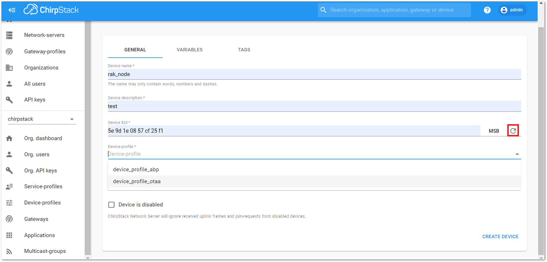 Figure 1: Generate a new Device EUI in the device registration form
LoRaWAN Join Mode
The LoRaWAN specification defines that to join in a LoRaWAN network, each end-device has to be personalized and activated. Activation can be done either via Over-The-Air-Activation (OTAA) or via Activation-By-Personalization (ABP). In OTAA, the end-device previously personalized is activated when deployed or reset. In ABP, personalization and activation are done as a single step.
Join in OTAA Mode
Configure the OTAA Mode on the Platform
- If you have selected “device_profile_otaa”, as shown in Figure 38, then after the device is created, an Application Key must be also created for this device.
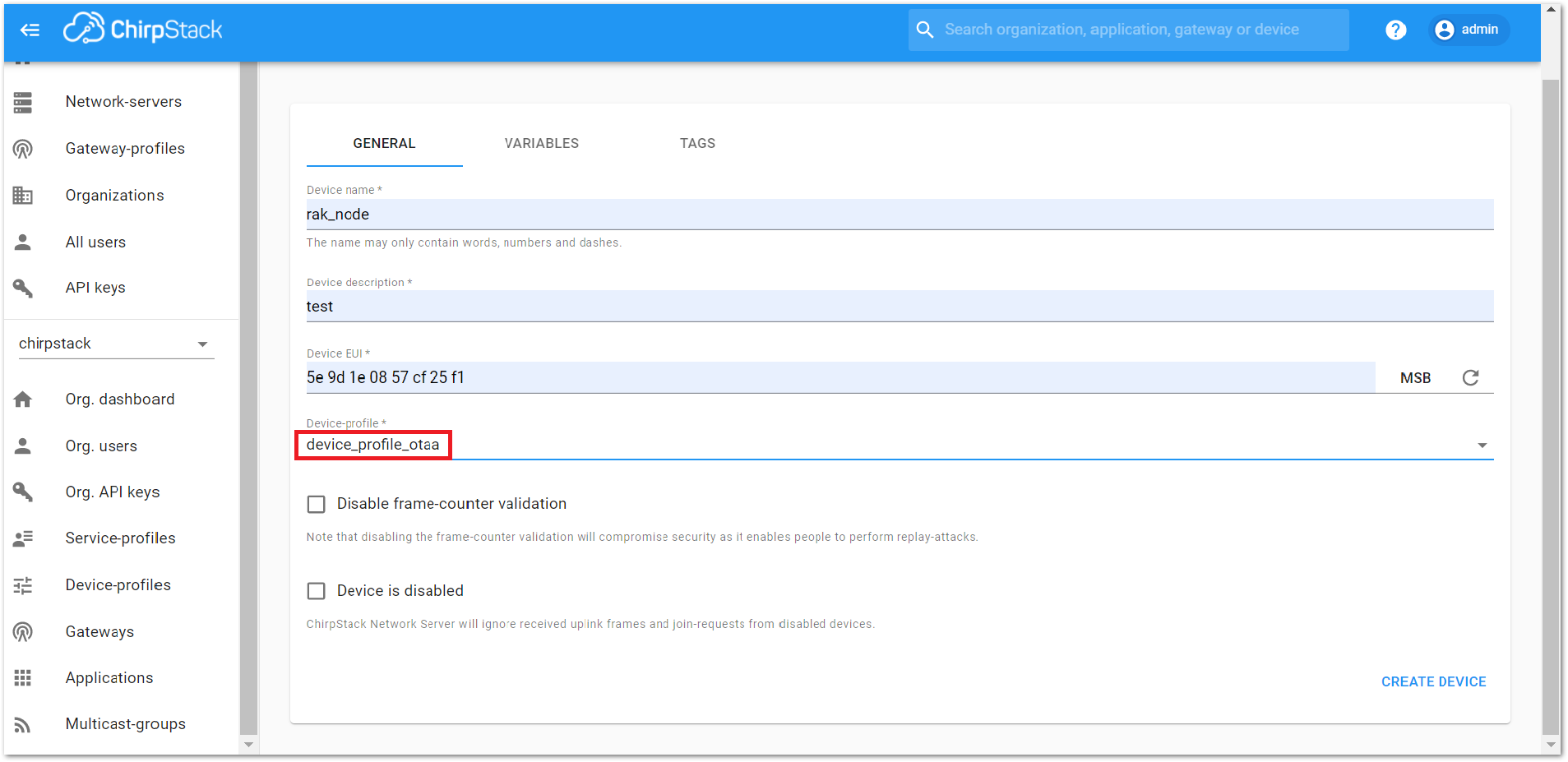 Figure 1: Choosing OTAA mode in the device registration form
- A previously created Application Key can be entered here, or a new one can be generated automatically by clicking the icon highlighted in red, as shown in Figure 39.
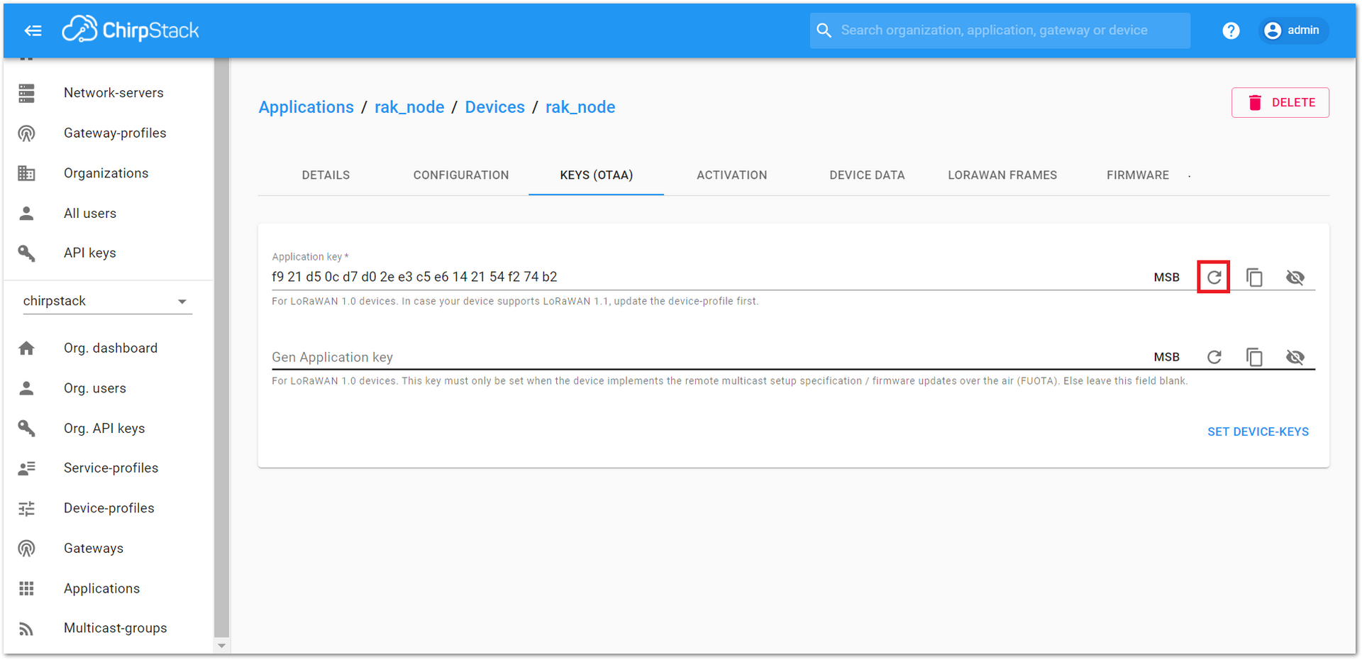 Figure 1: Application Key for the OTAA mode in the device registration form
-
Once the Application Key is added to the form, the process can be finalized by clicking on the “SET DEVICE-KEYS” button.
-
As shown in Figure 40, a new device should be listed in the “DEVICES” tab. The most important parameters, such as the Device EUI, are shown in the summary.
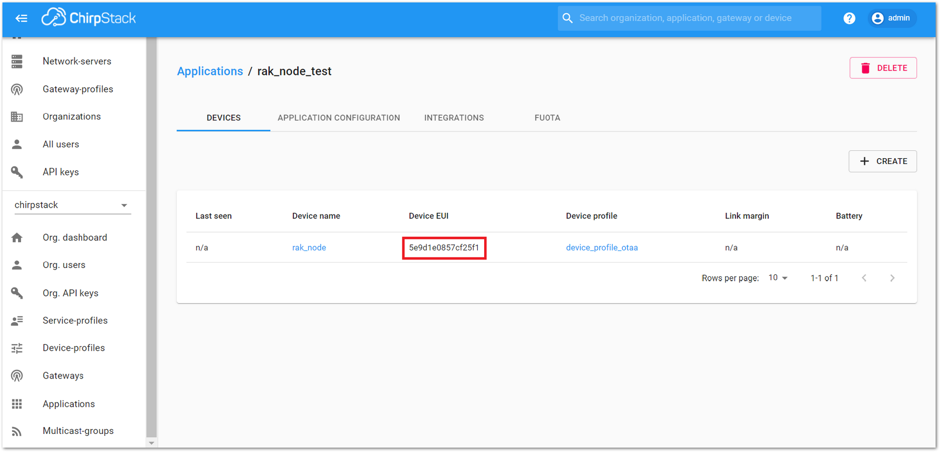 Figure 1: New created device listed in the DEVICES tab
- To end the process, it is a good practice to review that the Application Key is properly associated with this device. The Application Key can be verified in the “KEYS(OTAA)” tab, as shown in Figure 41.
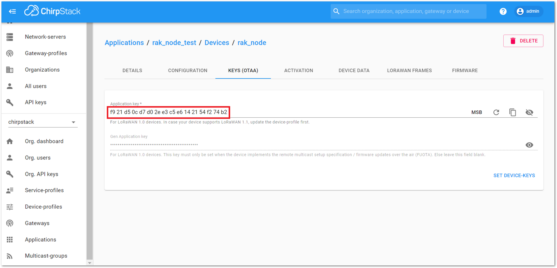 Figure 1: Application Key associated with the new device.
Standard OTAA mode requires the Device EUI, Application Key, and Application EUI; but in the ChirpStack implementation, only Device EUI and the Application Key are mandatory. The Application EUI is not required nor recorded in the Application tab. Nevertheless, the Application EUI is a mandatory parameter in the RAK4200 module firmware. To resolve this mismatch, reuse the Device EUI as the Application EUI during the configuration on the side of the node.
Configure the OTAA Mode on the RAK4200 Module
RAK4200 complies with LoRaWAN 1.0.2 specification. By default, the LoRa join mode is OTAA, and the LoRa Class is Class A.
To set up the RAK4200 module to join ChirpStack using OTAA, start by connecting the RAK4200 module to the computer (see Figure 1). Open the RAK Serial Port Tool, and wait for the communication to start. It is recommended to test the serial communication by sending an AT command as at+get_config=lora:status or at+version.
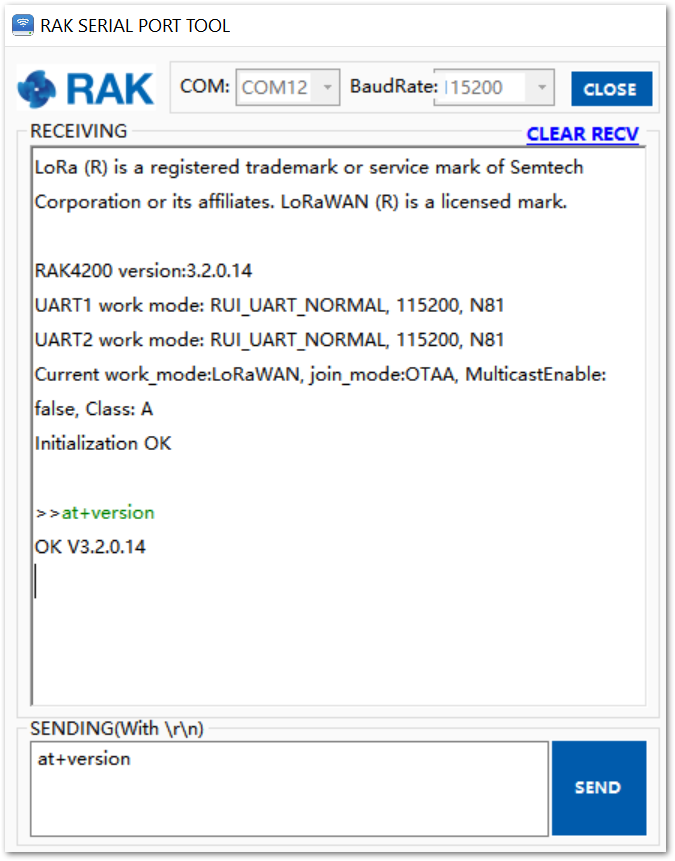 Figure 1: RAK Serial Port Tool connected to a RAK4200
As an example, the following parameters will be configured in RAK4200:
- LoRa join mode: OTAA
- LoRa class: Class A
- LoRa region: EU868
- Device EUI: 5e9d1e0857cf25f1 (from ChirpStack registration)
- Application EUI: 5e9d1e0857cf25f1 (from ChirpStack registration)
- Application Key: f921d50cd7d02ee3c5e6142154f274b2 (from ChirpStack registration)
- Set the LoRa join mode to OTAA.
at+set_config=lora:join_mode:0
- Set the LoRa Class to Class A.
at+set_config=lora:class:0
- Set the frequency/region.
For the Europe region, type the command:
at+set_config=lora:region:EU868
- Refer to the RAK4200 Datasheet for the list of supported frequencies.
- Set the Device EUI.
Get the Device EUI number from ChirpStack registration.
at+set_config=lora:dev_eui:5e9d1e0857cf25f1
- Set the Application EUI.
Get the Application EUI number from the ChirpStack registration.
at+set_config=lora:app_eui:5e9d1e0857cf25f1
The Application EUI parameter is not required in the ChirpStack platform; therefore, it is possible to use the same id as the Device EUI. Otherwise, the firmware will complain.
- Set the Application Key.
Get the Application Key from the TTN registration.
Type command:
at+set_config=lora:app_key:f921d50cd7d02ee3c5e6142154f274b2
- Save the RAK4200 parameters.
Reset the RAK4200 to save the parameters.
Figure 42 summarizes the set of commands sent over the console for setting the OTAA mode on the RAK4200.
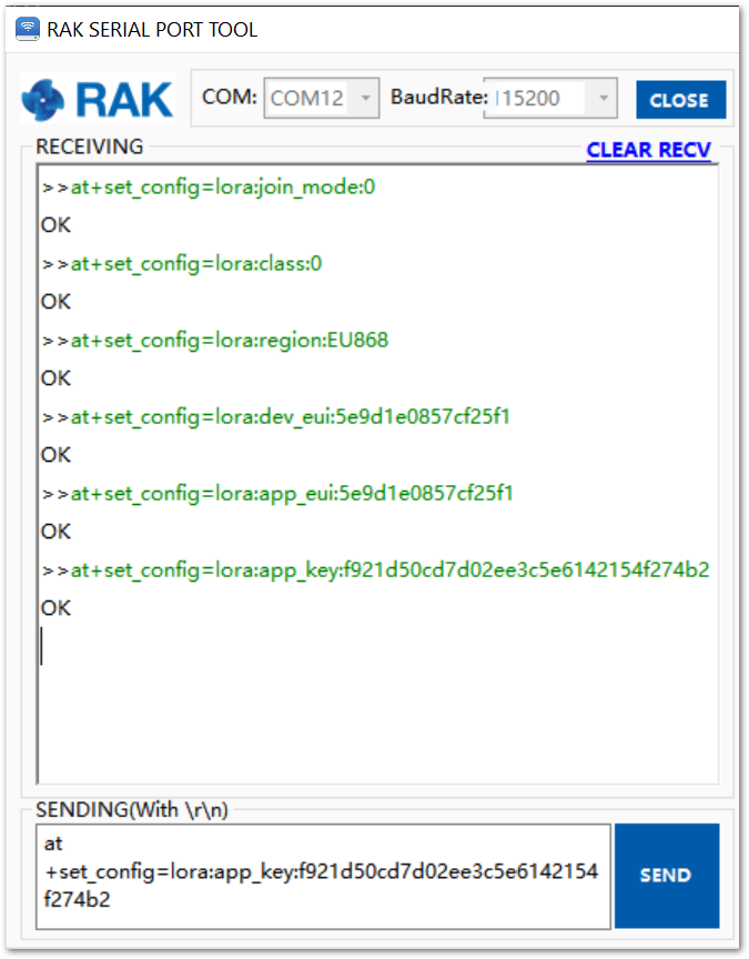 Figure 1: RAK4200 LoRa parameters configuration over the Serial Port Tool
- Send command to join in OTAA mode.
at+join
- If the request is successfully received by a LoRa gateway, then the “OK Join Success�” message will be shown in the serial console after a few seconds.
 Figure 1: RAK Serial Port Tool, join the network
The JoinRequest and JoinAccept messages are also displayed on the ChirpStack console, specifically in the “LORAWAN FRAMES” tab, as shown in Figure 45.
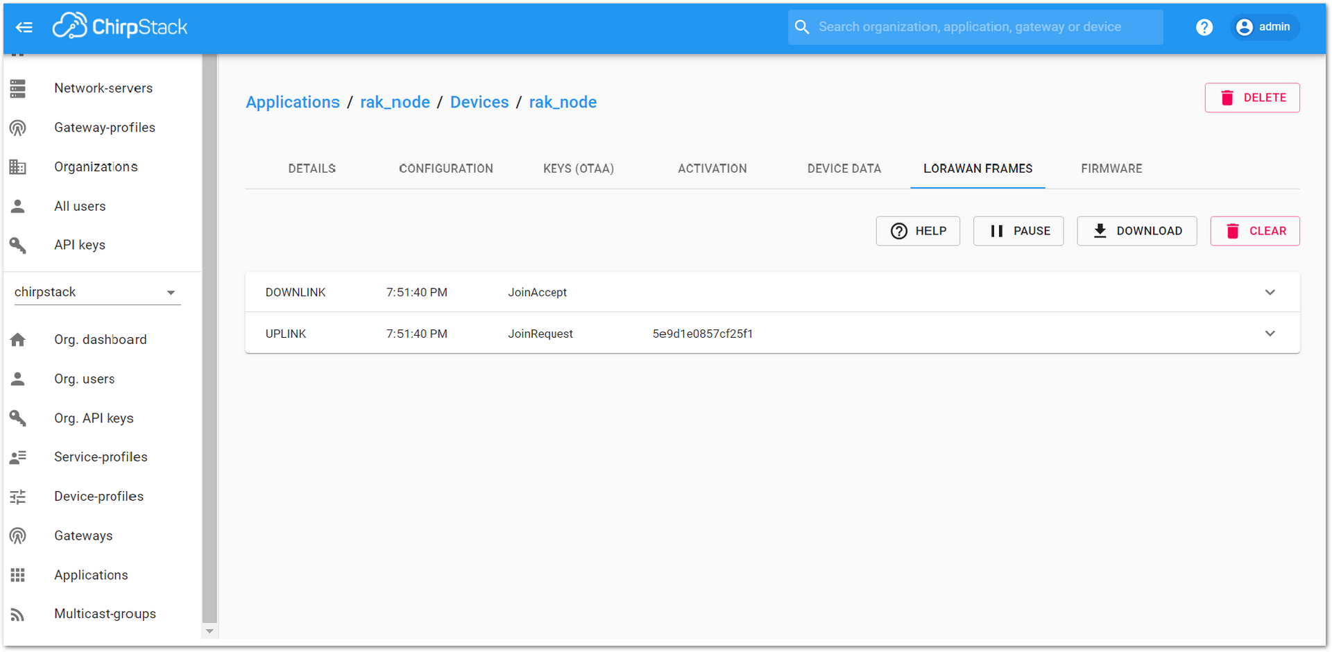 Figure 1: ChirpStack Console, checking LoRaWAN join request
- Send data from RAK4200 to ChirpStack.
To send the string 1234567890 over LoRa port 2, type the command:
at+send=lora:2:1234567890
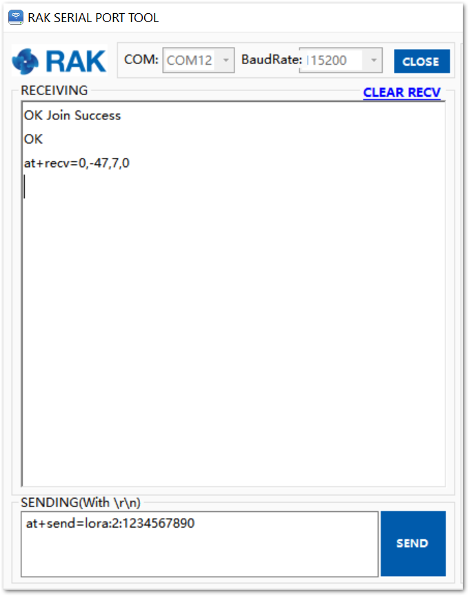 Figure 1: RAK Serial Port Tool, send a LoRaWAN message.
On the ChirpStack platform, the messages shall appear in the LORAWAN FRAMES tab, as shown in Figure 47. By convention, messages sent from nodes to gateways are considered as “UPLINK”, while messages sent by gateways to nodes are considered as “DOWNLINK”.
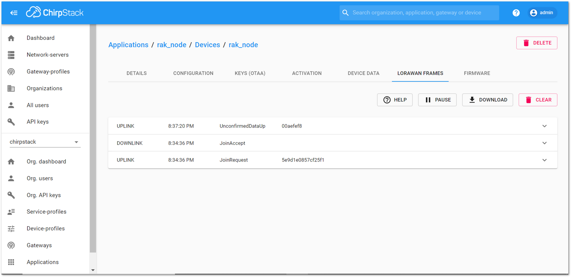 Figure 1: ChirpStack Console, checking LoRaWAN messages received.
Join in ABP Mode
Configure the ABP Mode on the Platform
During the registration of a new device, if “device_profile_abp” is selected, as shown in Figure 48, then the ChirpStack platform will assume that this device will join the LoRaWAN network using the ABP mode.
Check Disable frame-counter validation. If the server cannot synchronize the node-side counting, the transmission will fail.
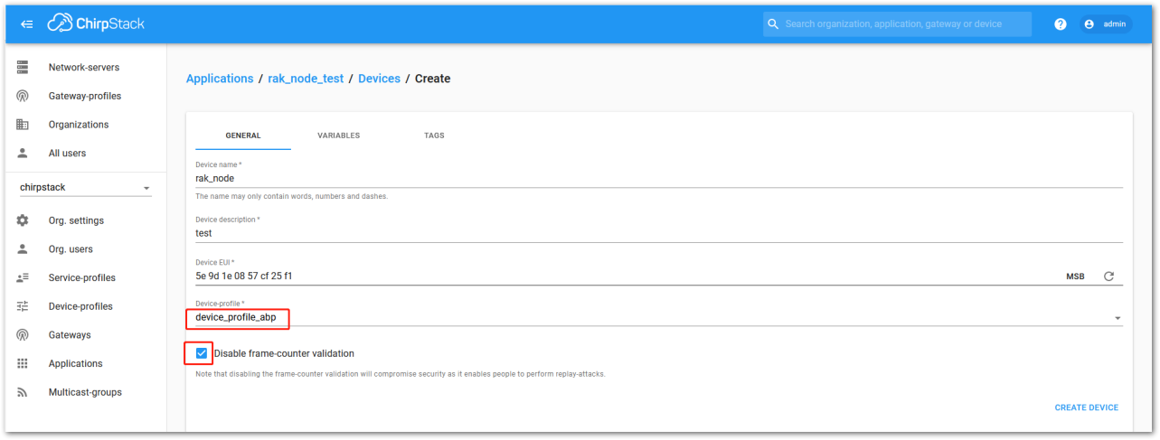 Figure 1: ChirpStack Console, configuring a device in ABP mode
After selecting the ABP mode, the following parameters appear in the Activation tab (See Figure 49):
- Device address
- Network Session Key
- Application Session Key
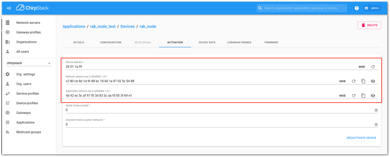 Figure 1: ChirpStack Console, parameters required for the ABP mode
The parameters can be generated as random numbers by the platform or you can set the values. Once these parameters are filled properly, the process is completed by clicking on the “(RE)ACTIVATE DEVICE” button.
Configure the ABP Mode on the RAK4200 Module
RAK4200 complies with LoRaWAN 1.0.2, by default the LoRa join mode is OTAA and the LoRa Class is Class A.
To set up the RAK4200 module to join ChirpStack using ABP, start by connecting the RAK4200 module to the computer (see Figure 1). Open the RAK Serial Port Tool, and wait for the communication to start. It is recommended to test the serial communication by sending an AT command as at+get_config=lora:status or at+version.
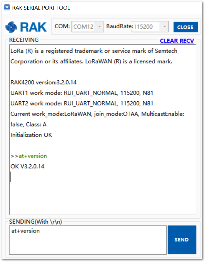 Figure 1: RAK Serial Port Tool connected to a RAK4200
As an example, the following parameters will be configured in RAK4200:
- LoRa join mode: ABP
- LoRa class: Class A
- LoRa region: EU868
- Device address: 26011af9 (from ChirpStack registration)
- Network Session Key: c280cb8d1df688bc18601a97025c5488 (from ChirpStack registration)
- Application Session Key: 4d42ec5caf97f03d833cdaf5003f69e1 (from ChirpStack registration)
- Set the LoRa join mode to ABP.
at+set_config=lora:join_mode:1
- Set the LoRa Class to Class A.
at+set_config=lora:class:0
- Set the frequency/region.
For the Europe region, type the command:
at+set_config=lora:region:EU868
- Refer to the RAK4200 Datasheet for the list of supported frequencies.
- Set the Device Address.
Get the Device Address from ChirpStack registration.
at+set_config=lora:dev_addr:26011af9
- Set the Network Session Key.
Get the Network Session Key from the ChirpStack registration.
at+set_config=lora:nwks_key:c280cb8d1df688bc18601a97025c5488
- Set the Application Key.
Get the Network Session Key from the ChirpStack registration.
at+set_config=lora:apps_key:4d42ec5caf97f03d833cdaf5003f69e1
- Save RAK4200 parameters.
Reset the RAK4200 to save the parameters.
Figure 51 summarizes the set of commands sent over the console to set the ABP mode on RAK4200.
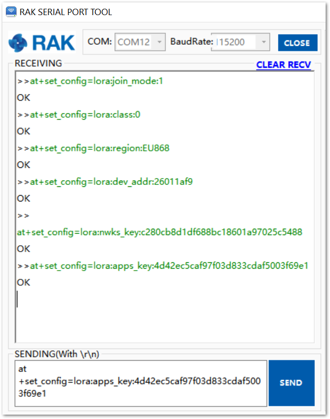 Figure 1: RAK4200 LoRa parameters configuration over the Serial Port Tool
- Send command to join in ABP mode.
All the parameters required to join to a LoRaWAN network in OTAA mode have been configured. After the reset, you can send the join command:
at+join
Right after sending the command, the “OK Join Success” should be replied to in the console, as shown in Figure 52.
 Figure 1: RAK4200 Serial Port Tool join
The ABP mode in LoRaWAN does not require to join a network before sending a LoRaWAN package to the air. Moreover, to keep the consistency of the internal states of the firmware of the RAK4200 module, it is still required to send the at+join command in the ABP mode.
- Send data from RAK4200 to ChirpStack.
To send the string 1234567890 over LoRa port 2, type the command:
at+send=lora:2:1234567890
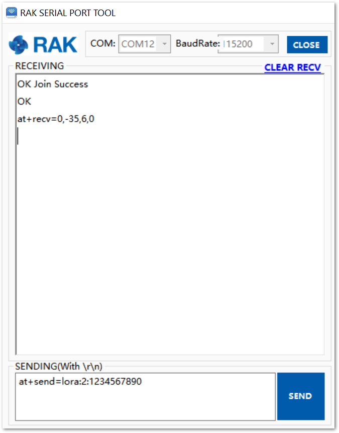 Figure 1: Sending a message in ABP mode
- The console will feedback with an “OK” message (see Figure 53). The sent data shall be displayed in the ChirpStack console.
LoRa P2P Mode
This section will show how to set and link two RAK4200 units to work in LoRa P2P mode. The two RAK4200 units shall be set to operate at the same frequency, e.g: EU868.
As shown in the previous sections, the setup of the RAK4200 units is done by connecting them with a general-purpose computer through the UART port. The setup of each RAK4200 can be done separately, but testing the LoRa P2P mode will require having both units connected simultaneously to a UART port (this could be one computer with 2 ports or 2 computers with one UART port each).
- To set the RAK4200 to work in LoRa P2P mode, open the RAK Serial port tool and send the command, as shown in Figure 54:
at+set_config=lora:work_mode:1.
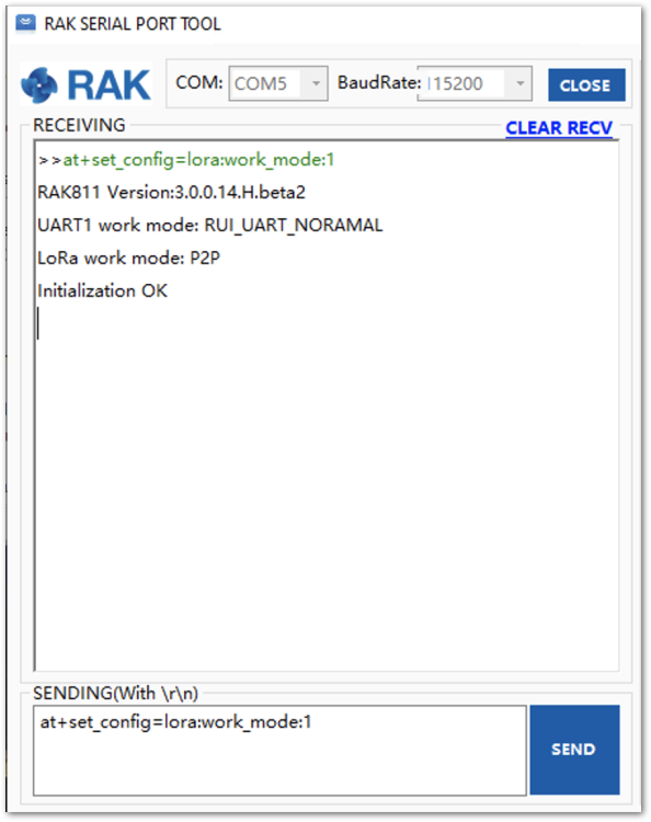 Figure 1: RAK4200 setting to LoRa P2P mode
- Configure the LoRa P2P parameters for both units. The command for setting the parameters has the format.
at+set_config=lorap2p:XXX:Y:Z:A:B:C
The parameters are as follows:
- XXX: Frequency in Hz.
- Y: Spreading factor, [6, 7, 8, 9, 10, 11, 12].
- Z: Bandwidth, [0:125 kHz, 1:250 kHz, 2:500 kHz]
- A: Coding Rate, [1:4/5, 2:4/6, 3:4/7, 4:4/8]
- B: Preamble Length, 5~65535.
- C: Power in dBm, 5~20.
For this example, the LoRa parameters are:
- Link frequency: 869525000 Hz
- Spreading factor: 7
- Bandwidth: 125 kHz
- Coding Rate: 4/5
- Preamble Length: 5
- Power: 5 dBm
- It is translated into the following RAK4200 AT command that is sent to both units, as shown in Figure 55:
at+set_config=lorap2p:869525000:7:0:1:5:5
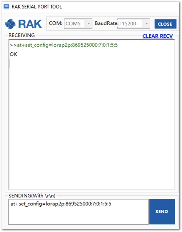 Figure 1: Setting both RAK4200 units with the LoRa P2P parameters
- Next, set the transmission mode of the module. In this example, Unit 1 is set to sender mode, and unit 2 is set to receiver mode by AT command. See Figure 56.
Unit 1(Sender): at+set_config=lorap2p:transfer_mode:2
Unit 2(Receiver): at+set_config=lorap2p:transfer_mode:1
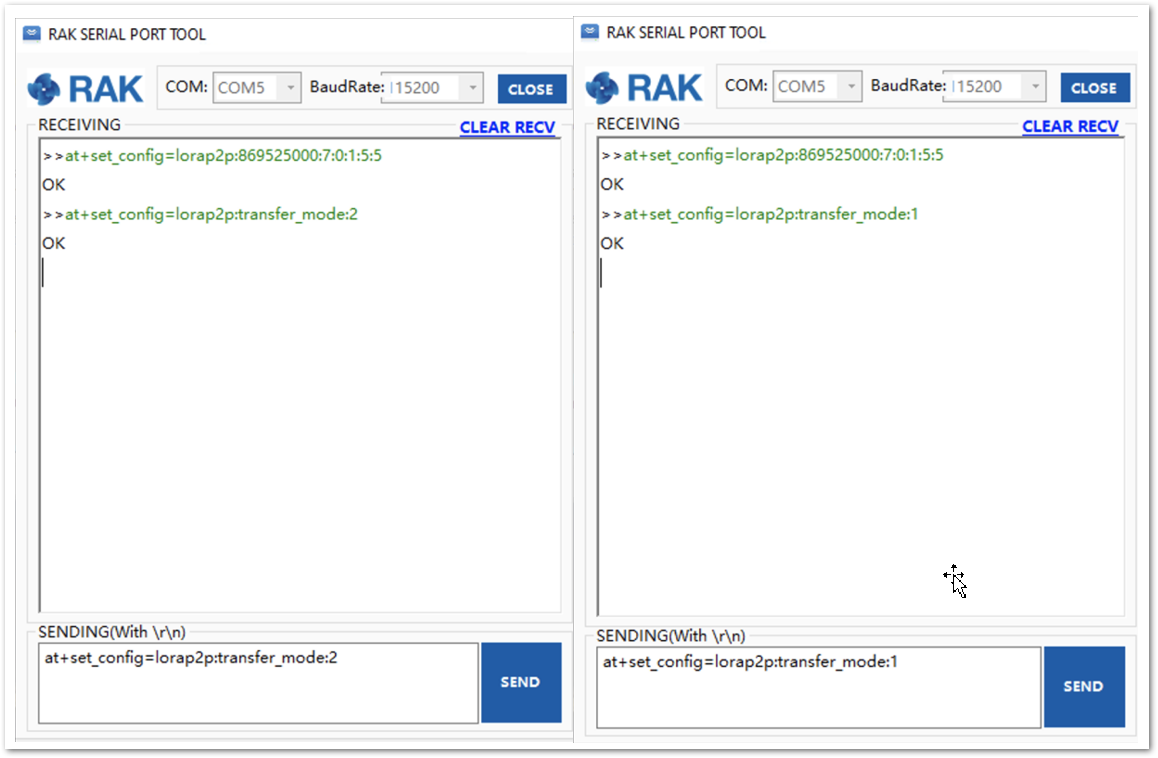 Figure 1: Set the module in the sender (left) and in the receiver (right) mode
- To send a message with the string “123456890” from Unit 1 to Unit 2, use the command on Unit 1:
at+send=lorap2p:1234567890
The message will be automatically received by Unit 2. See Figure 57.
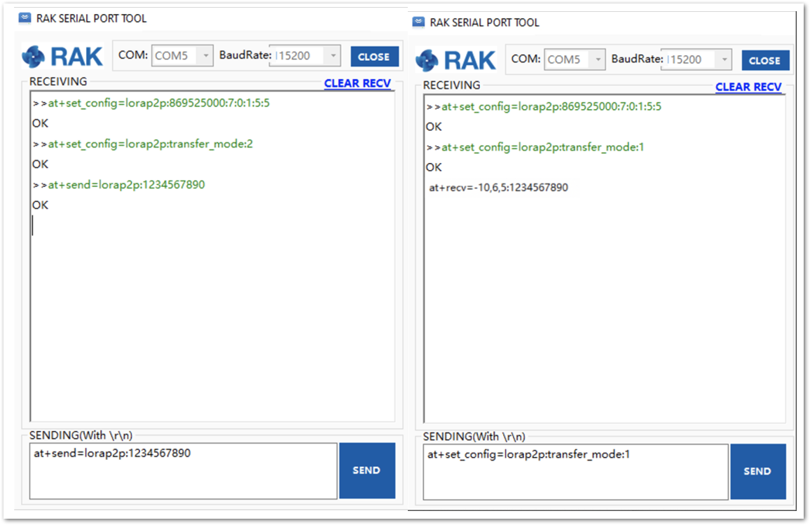 Figure 1: Sending a message from RAK unit 1(left) to RAK unit 2 (right)
Miscellaneous
Firmware Update
Before to start working with the RAK4200, it is recommended to keep the RAK4200 module updated to the latest version of the firmware.
For RAK4200 modules with firmware version V3.0.0.12 and below, you need to use the STM32CubeProgrammer to upgrade your firmware and upload the .hex file (not the .bin file) of the latest RAK4200 firmware. The lower versions of the firmware have a different bootloader code and will not work on the RAK DFU Tool.
In the following sections, two (2) options for flashing new firmware in a RAK4200 module are shown: “Firmware Upgrade through DAPLink” and “Firmware Upgrade through UART1”.
Firmware Upgrade Through DAPLink
Refer to the RAKDAP1 Flash and Debug Tool Quickstart Guide.
Firmware Upgrade Through UART1
Minimum Hardware and Software Requirements
| Computer | A Windows/Linux/Mac computer |
| Firmware File | Bin firmware downloaded from the website. |
| Others | A USB to TTL adapter. |
Firmware Upgrade Procedure
Follow this procedure to upgrade the firmware in Device Firmware Upgrade (DFU) mode through the UART1 interface.
-
Download the latest application firmware of the RAK4200 module.
-
Download the RAK Device Firmware Upgrade (DFU) tool. In this folder are the different DFU tools depending on your machine's OS.
-
Connect the RAK4200 module with a computer through USB to TTL adapter as shown in Figure 58:
-
Open the RAK Device Firmware Upgrade (DFU) tool. Select the serial port and baud rate of the module, and then click on the "Select Port" button.
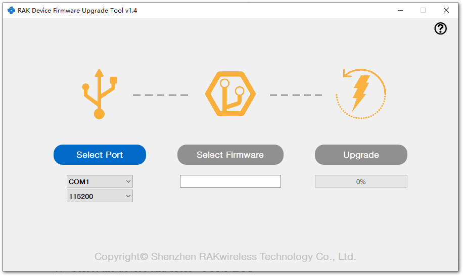 Figure 1: Device Firmware Upgrade Tool
- Click on the "Select Firmware" button and choose the application firmware file of the module with the suffix ".bin".
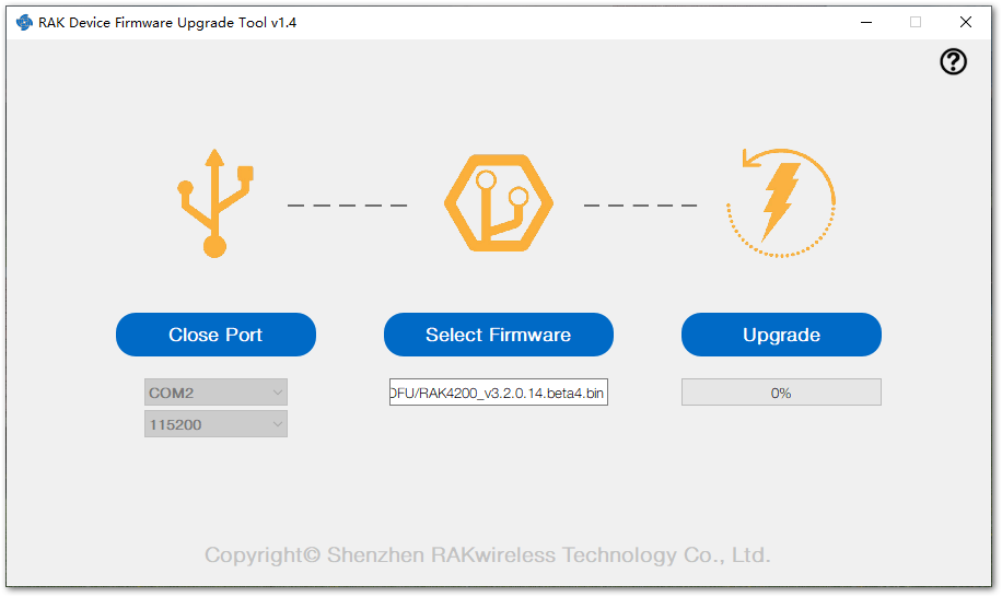 Figure 1: Select firmware
- Click on the "Upgrade" button to upgrade the device. After the upgrade is complete, the RAK4200 module is now ready to work with the new firmware.
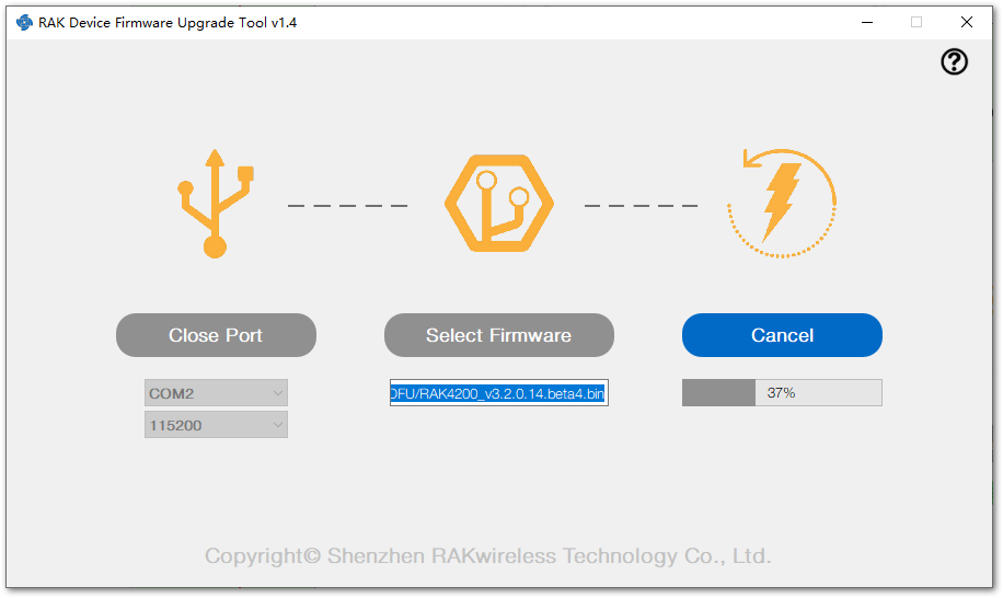 Figure 1: Firmware upgrading
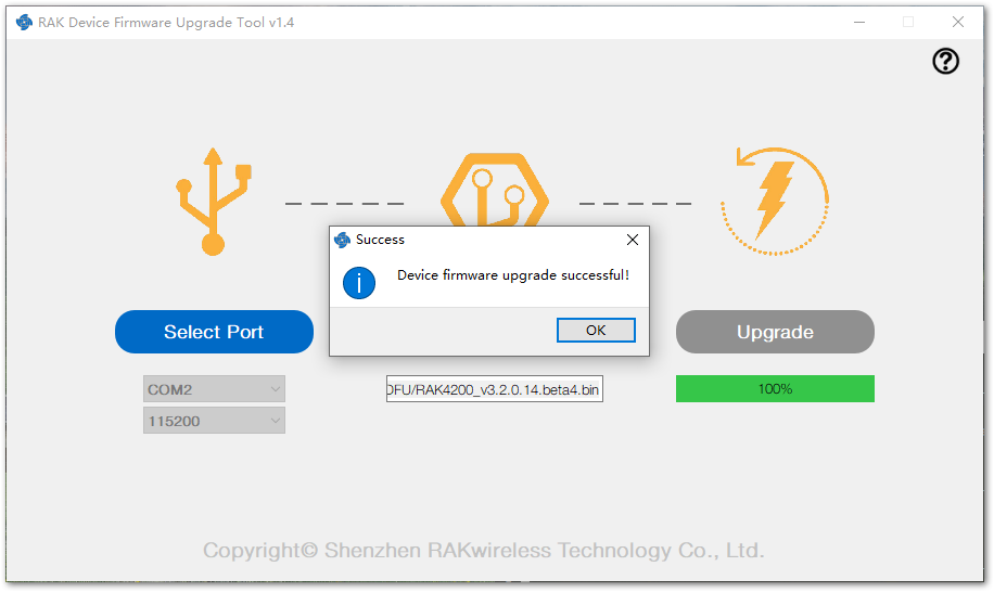 Figure 1: Upgrade successful