RAK4260 Module Quick Start Guide
Prerequisites
What Do You Need?
Before going through the quick start guide of the RAK4260 WisDuo LPWAN Module, make sure to prepare the necessary items listed below:
Hardware Tools
- RAK4260 LPWAN Module
- USB to TTL Converter
- RAKDAP1 DAPLink Tool
- Gateway in range for testing
- Windows PC
Software Tools
Product Configuration
Interfacing with RAK4260
During the configuration of the module, a guided setup is available on the console output. You can connect to the console of the RAK4260 module through the UART interface.
Connect to the RAK4260
In this document, a RAK4260 module is used as an example. Use a USB to TTL converter to connect to the module.
- Connect the RAK4260 to the USB port of a general-purpose computer (Windows PC) using a USB to TTL module (3.3 V), as shown in Figure 1.
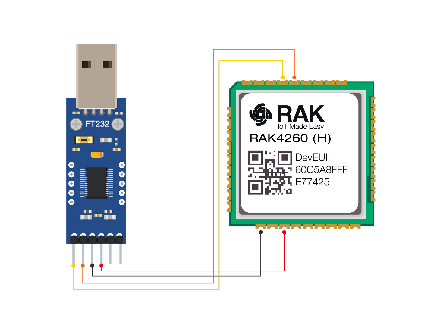 Figure 1: RAK4260 Module Connection
-
Any serial communication tool can be used. However, it is recommended to use the RAK Serial Port Tool.
-
Configure the serial communication tool by selecting the proper port detected by the computer and configure the link as follows:
- Baud Rate: 115200 bauds
- Data Bits: 8 bits
- Stop Bits: 1 stop bit
- Parity: NONE
- The RAK4260 console output can now be read in the RAK serial port tool, as shown in Figure 2.
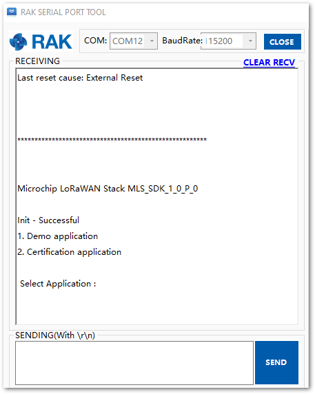 Figure 1: RAK Serial Port Tool Connected to RAK4260 Module
Before establishing a LoRa Connection using the RAK4260 Module, several configurations must be set first, which will be discussed in the next sections.
Connecting to the Things Network (TTN)
In this section, a practical exercise will be performed to show how to connect the RAK4260 module to The Thing Network (TTN) platform.
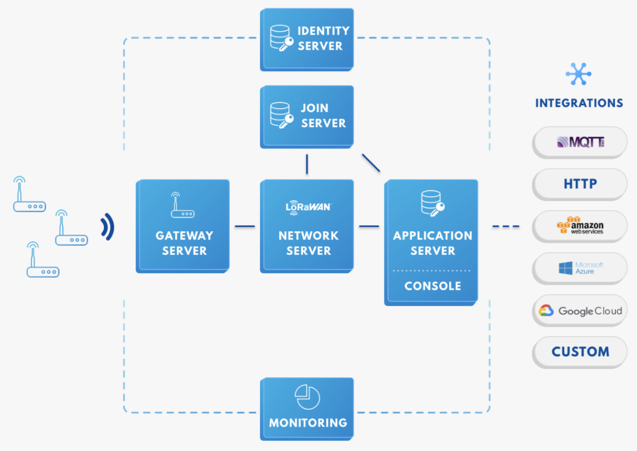 Figure 1: RAK4260 in the context of the TTN
As shown in Figure 3, the RAK4260 module is one of the devices located on the left side. In the context of an IoT solution, the objective is to deploy devices to sense the relevant process variables and transmit the data to the backend servers located in the cloud. The data will be processed and integrated as part of a larger solution that could generate efficiency, traceability, and predictability capacity among others.
The RAK4260 module can be part of this ecosystem, and the objective of this section is to demonstrate how simple to send data to the TTN using the LoRaWAN protocol. To achieve this, the RAK4260 module must be located inside of the coverage of a LoRaWAN gateway.
Sign up and log inIf you don't have an account yet, head on to the TTN website and create one. Once done, log in to your account and go to the Console.
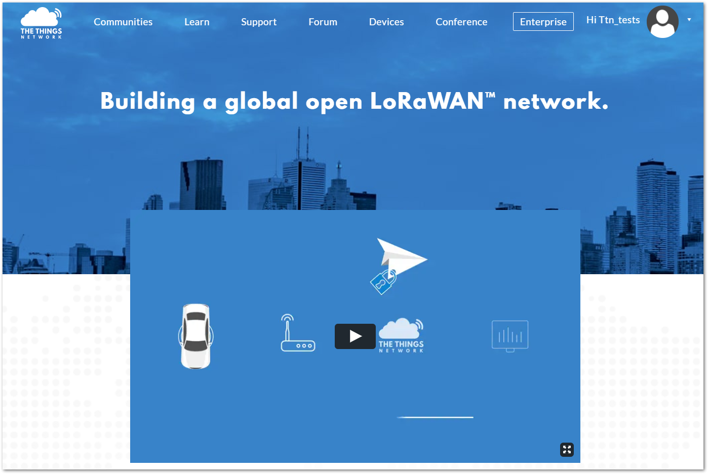 Figure 1: The Things Network Home Page
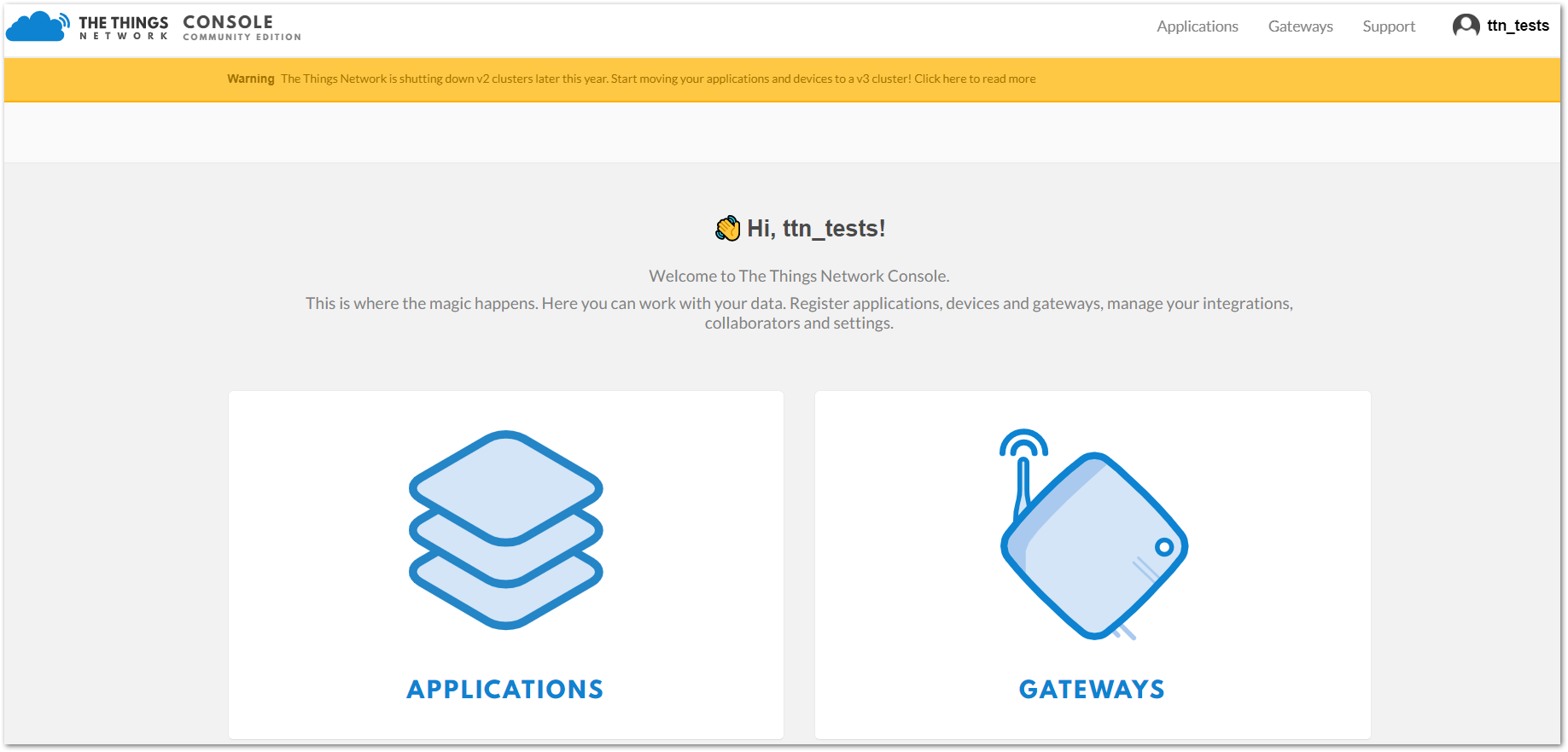 Figure 1: TTN Console Page
Create a New Application
- Choose the APPLICATIONS.
 Figure 1: Application Section
- Click the “add application” button.
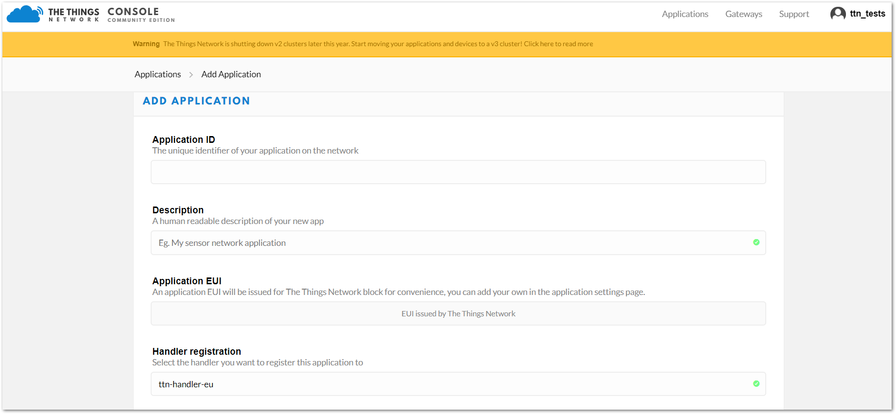 Figure 1: Adding an Application
-
Here are the things that you should take note of in adding an application:
- Application ID - this will be the unique ID of your application in the Network. Note that the characters should be in lower case, no spaces are allowed.
- Description - this is a short and concise human-readable description of your application.
- Application EUI - this will be generated automatically by The Things Network for convenience.
- Handler Registration - handler you want to register this application to.
- After you fill in the necessary information, press the "Add application" button at the bottom of this page. If you see a similar page, as shown in Figure 8, then you have successfully registered your application.
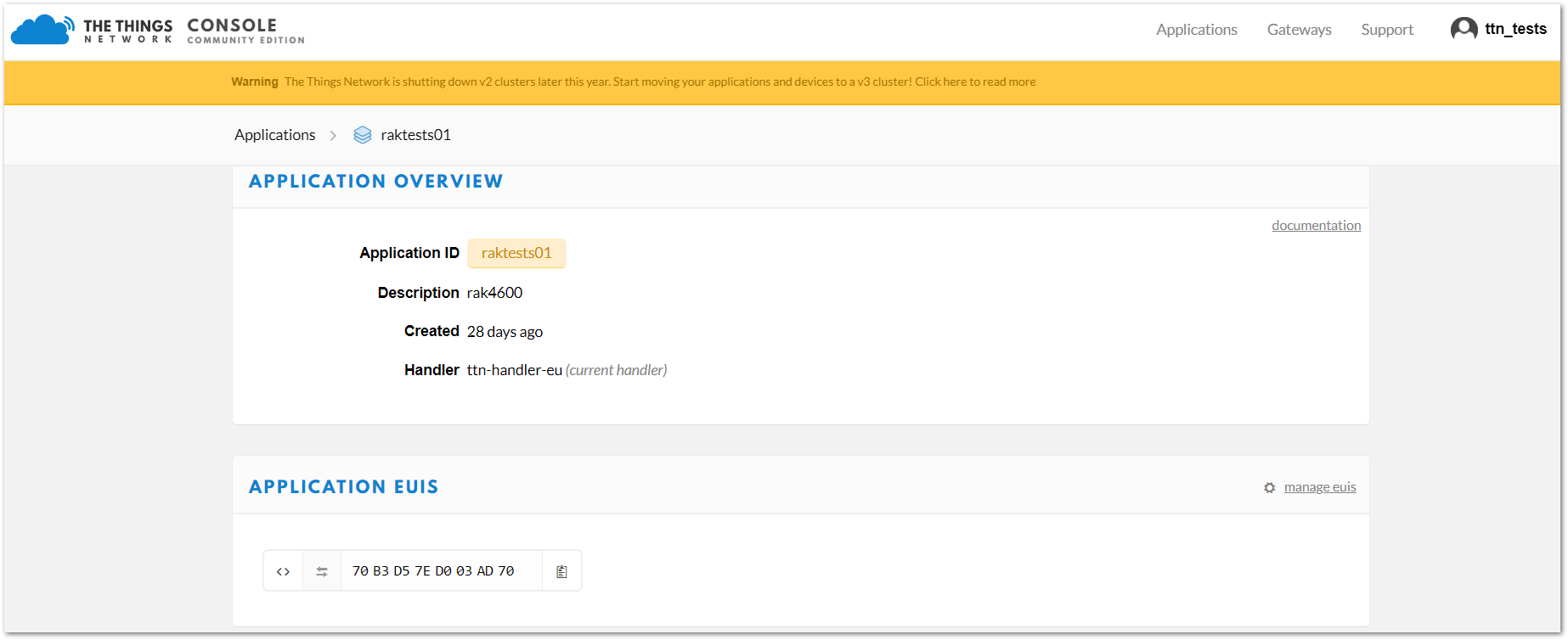 Figure 1: Application Overview
- Scroll down until you see the Devices section. Or, you can click the "Devices" button at the top.
 Figure 1: Register a New Device
- Then, register a new device by clicking on the "register devices".
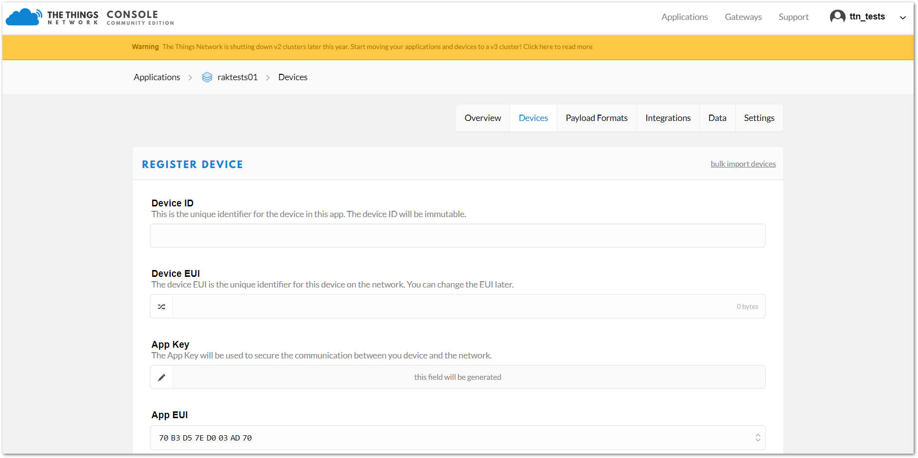 Figure 1: Add your Device
In this form, the device ID must be unique for the application and must be completed with lower case, alphanumeric characters. The rest of the parameters in the form are very important for the LoRaWAN protocol:
- Device EUI
- Application Key
- Application EUI
The TTN platform can generate these parameters randomly by leaving those fields empty, or you can enter already existing values.
- Press the “Register” button at the bottom of this page to finish the process.
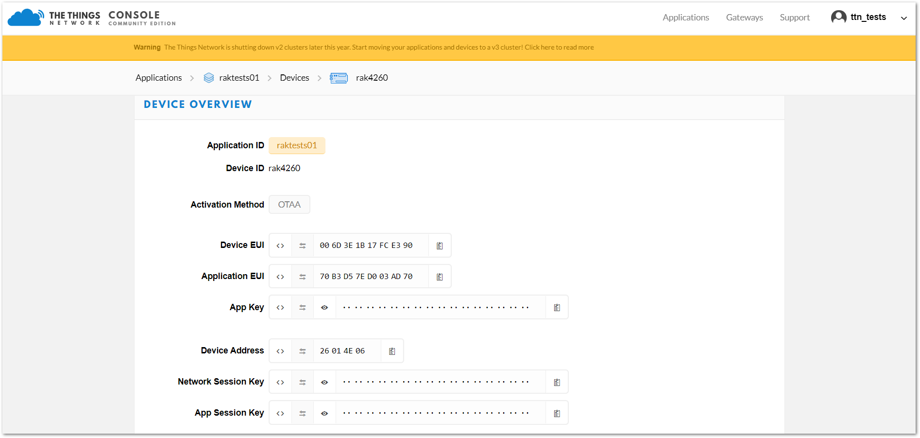 Figure 1: Device Overview
Configuring RAK4260 LPWAN Module
To connect the RAK4260 module to a LoRa P2P Connection or a LoRaWAN network, the module must be configured and LoRa parameters must be set properly. This can be done by modifying the LoRa parameters on the firmware source code and flashing it into the module. The following section will guide you through the process of doing this using Atmel Studio.
Parameter and Firmware Setup
To connect your device with TTN, execute the following steps. To do this, fill in the parameters obtained when setting up the TTN.
Edit OTAA Parameters in the Code
- Open your Atmel Studio and navigate to the demo firmware you downloaded from the RAKwireless GitHub repository.
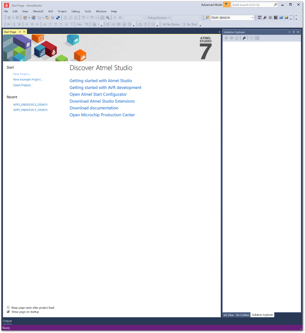 Figure 1: Atmel Studio Main Page
- Go to File → Open → Project/Solution.
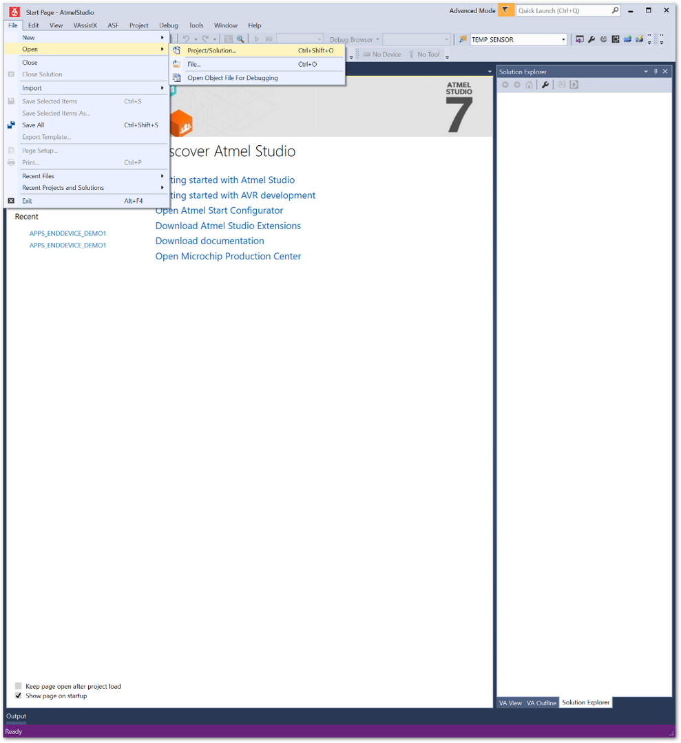 Figure 1: Open the sample project
- Go to the folder where you downloaded the GitHub repository, and select the "APPS_ENDDEVICE_DEMO1" project file (it is in the directory with the same name as the file). Then click Open.
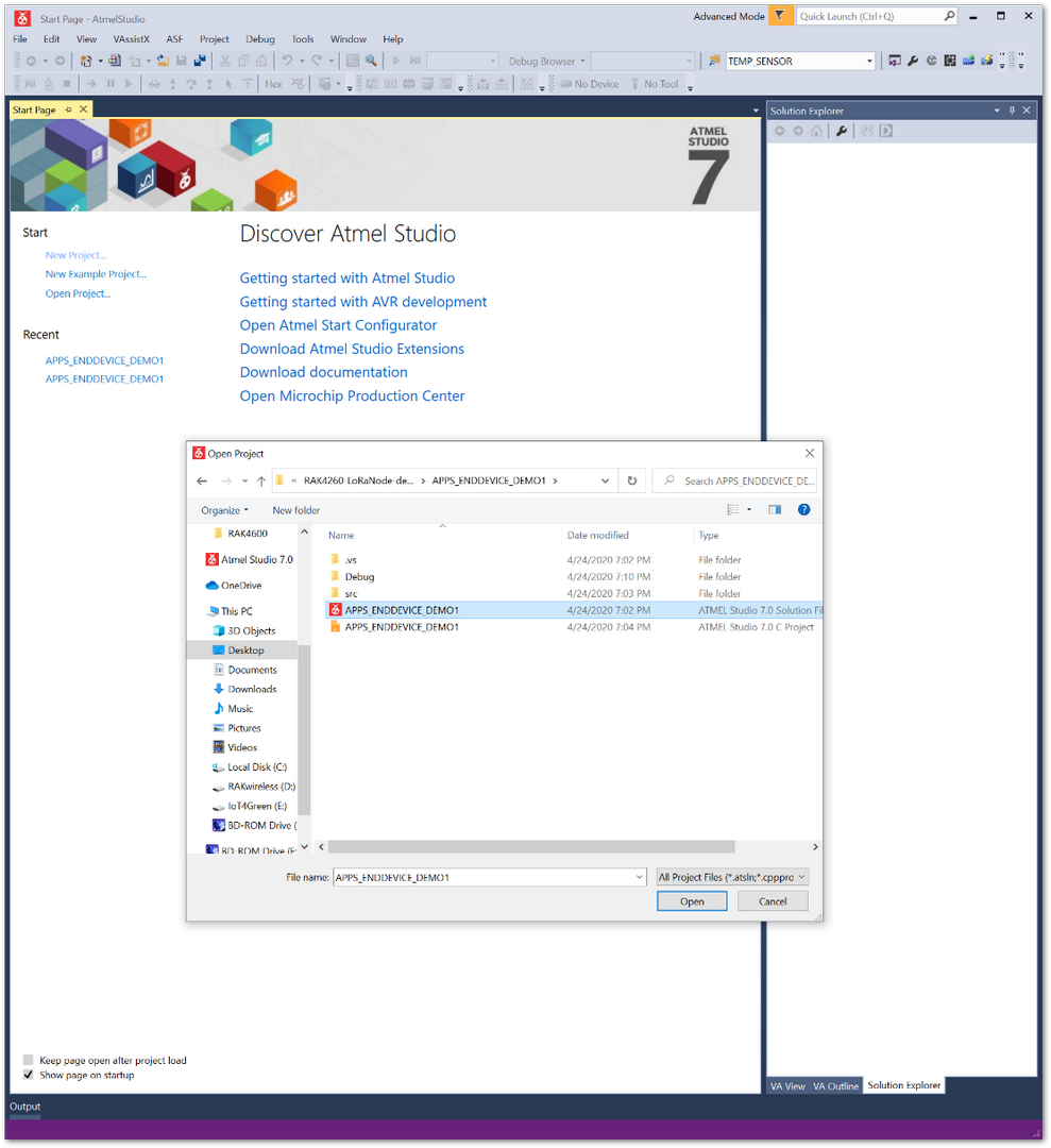 Figure 1: Demo firmware project file
- Once your project has loaded up, you will be presented with a file structure that contains folders and files that you can edit. You need to copy the values of the three (3) parameters shown in Figure 11 (Device, Application EUI, and Application Key) into the corresponding fields in the “conf_app.h” file. It is contained in the scr config folder that you can access via Solution Explorer tree.
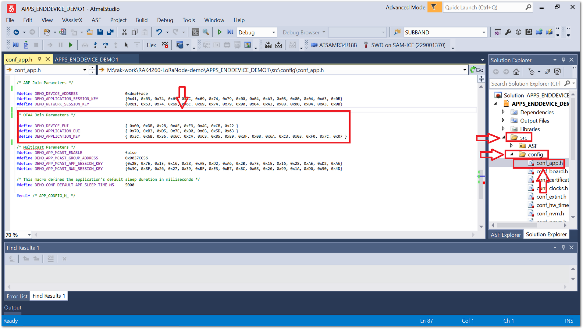 Figure 1: Device configuration file (OTAA parameters)
- After replacing the default values with the one for the device you registered with TTN, you can proceed to compile the project. There is no need to edit anything else in order to compile firmware that will allow you to connect to the TTN network.
Compile the Code
- Compile the code by going to the Build → Build Solution.
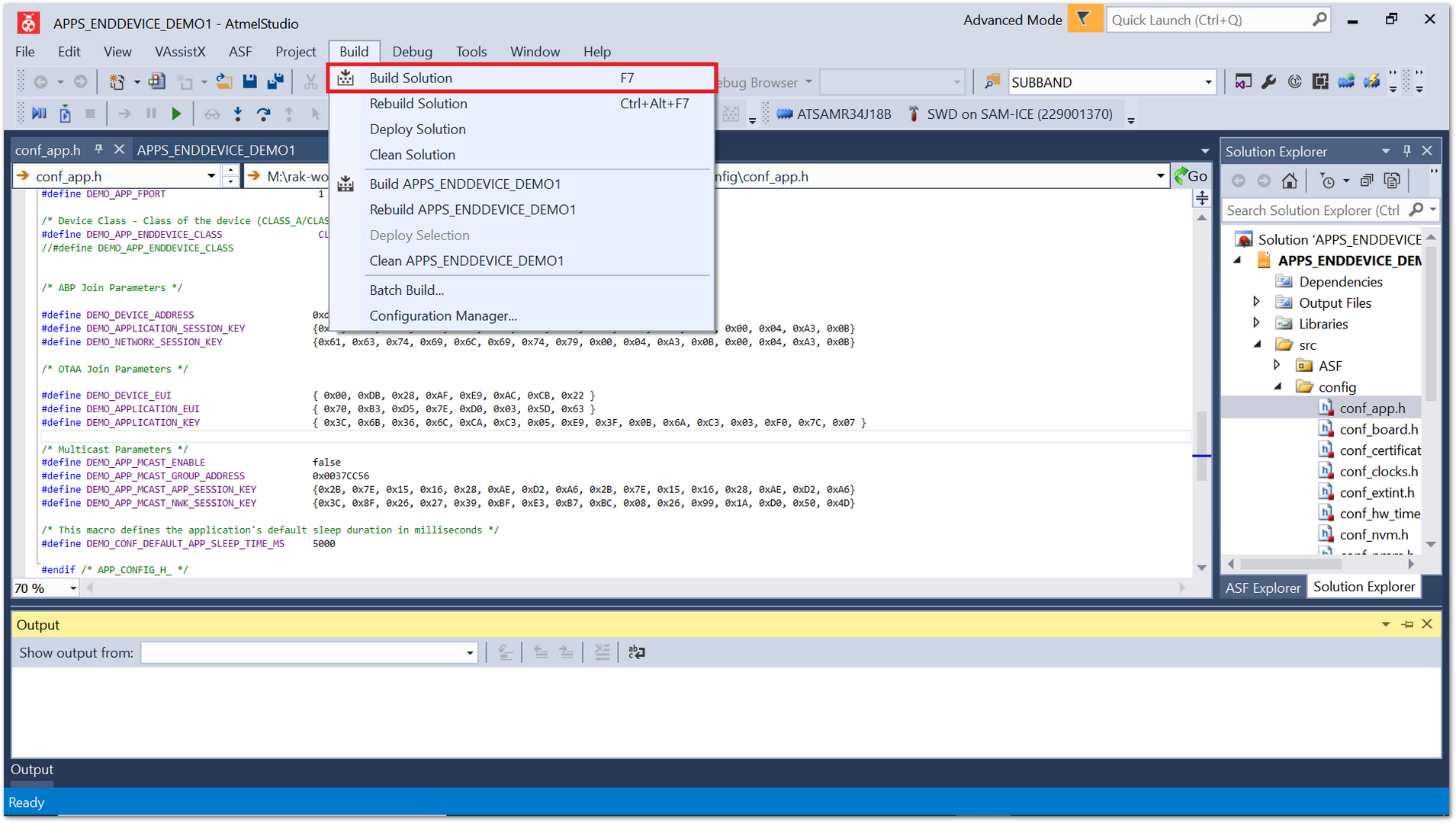 Figure 1: Compiling the code
- The output should have no errors, as shown in Figure 17.
 Figure 1: Compiling the code
Flashing the Firmware
Once compiled, you can find the output file in the “Debug” folder of the directory where you downloaded the firmware. See Figure 18.
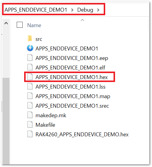 Figure 1: Firmware .hex file
- As the firmware is ready, proceed to flashing it. In order to do this, you need to utilize your RAKDAP1 hardware tool and the pyocd software tool.
Flash the Firmware Using RAKDAP1
Refer to the RAKDAP1 Flash and Debug Tool.
Connecting to TTN
- Connect your USB to the TTL adapter to the corresponding pins of RAK4260, which have been discussed in the earlier section. Refer to Figure 1.
Use the serial communication tool to use the guided setup. Based on the firmware you flashed to the RAK4260 Module, it is configured in OTAA Mode. To initiate the connection to TTN, press the key "1" to enter into the Demo Application. A list of frequencies will appear on the console output, choose the one that suits your application. In this example, EU868 is used for the region, since it was the configured parameter at the LoRa gateway. Sample console output is shown in Figure 19.
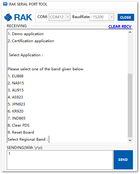 Figure 1: Demo application response
- Make sure to set the proper configuration in-line with the LoRa Gateway settings to successfully connect the RAK4260 module to a LoRa network.
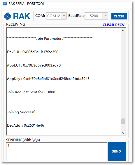 Figure 1: Join request which shows configured parameters
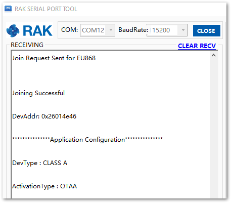 Figure 1: Connection successful for OTAA mode
- Try to send data after a successful connection to the TTN, by pressing the key "2" for the "Send Data" option.
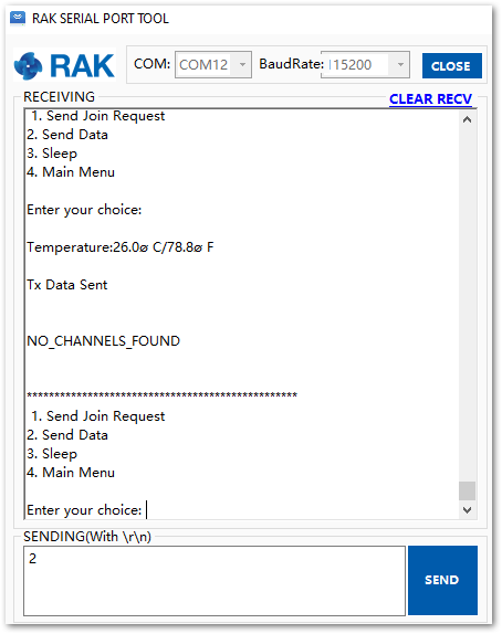 Figure 1: Join request which shows configured parameters
- As you can see, the sample data were sent successfully and should be expected to appear on TTN Console.
 Figure 1: Received data on TTN side
Connecting to ChirpStack
This section shows how to connect the RAK4260 LPWAN Module to the ChirpStack platform. As described in the ChirpStack website:
“ChirpStack provides open-source components for LoRaWAN networks. Together they form a ready-to-use solution including a user-friendly web interface for device management and APIs for integration. The modular architecture makes it possible to integrate within existing infrastructures. All components are licensed under the MIT license and can be used for commercial purposes.”
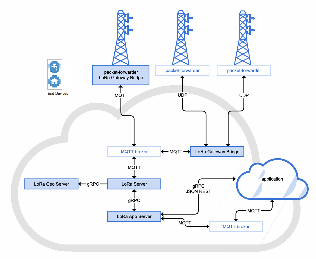 Figure 1: RAK4260 LPWAN Module in the context of the ChirpStack platform
The architecture of the ChirpStack platform is shown in the previous figure. Similar to the case of TTN, the RAK4260 Module is an End Device and will transmit the data to the backend servers through a LoRa gateway. For a more technical understanding of the ChirpStack components, refer to the Architecture page of ChirpStack.
To register the device to the ChirpStack network server, you must choose either ABP or OTAA mode.
Create a New Application
-
To connect the RAK4260 Module to ChirpStack, first, you need to create an Application.
-
Go to the Applications section then click on the “+ CREATE” button.
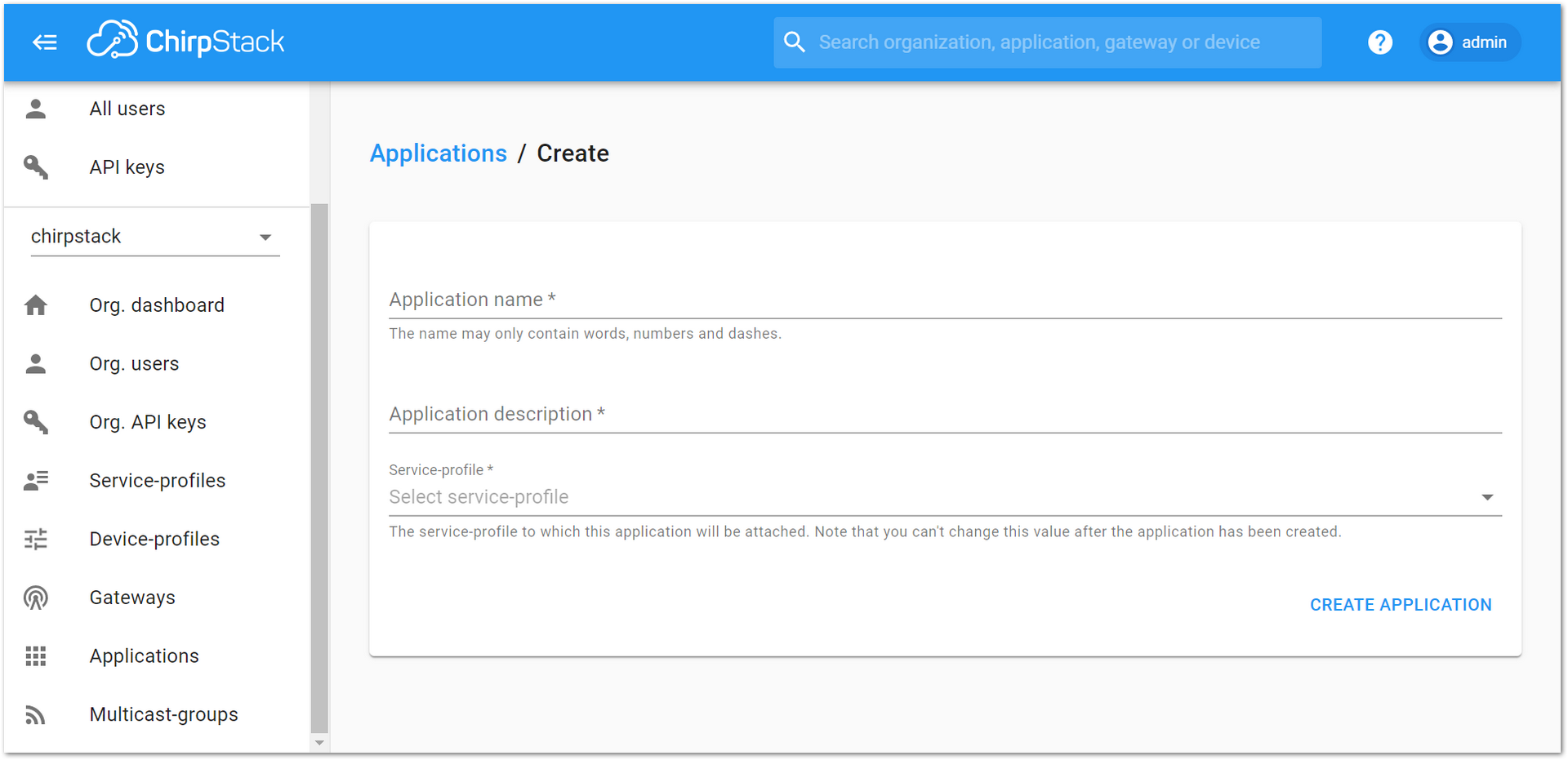 Figure 1: Creating a new Application
-
Create an Application named rak4260_node. Fill in the required fields, as shown in Figure 25.
-
To finish, click the “CREATE APPLICATION” button.
ChirpStack LoRaServer supports multiple system configurations, with only one by default. By default, a new Application should be created, although it is possible to reuse the existing ones.
- Application Name: rak4260_node
- Application Description: RAK4260 Module application
- Service profile: This field will select the system profile.
The Application Description field is just a descriptive text.
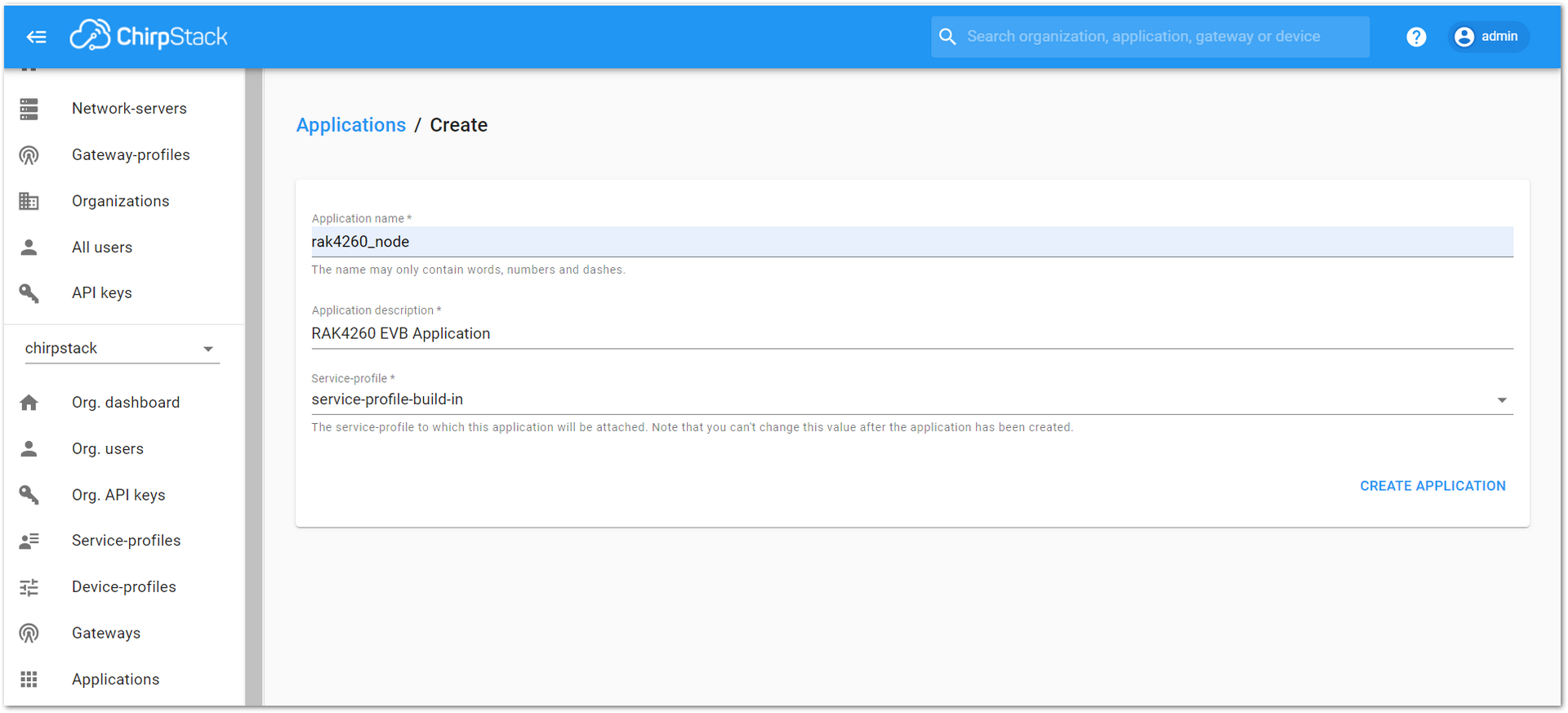 Figure 1: Filling the Application Parameters
Registering a New Device
- Click on the Application rak4260_node created in the previous step.
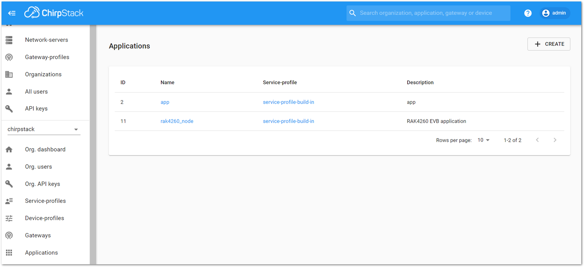 Figure 1: List of applications created
- Select the “DEVICES” tab, as shown in Figure 28.
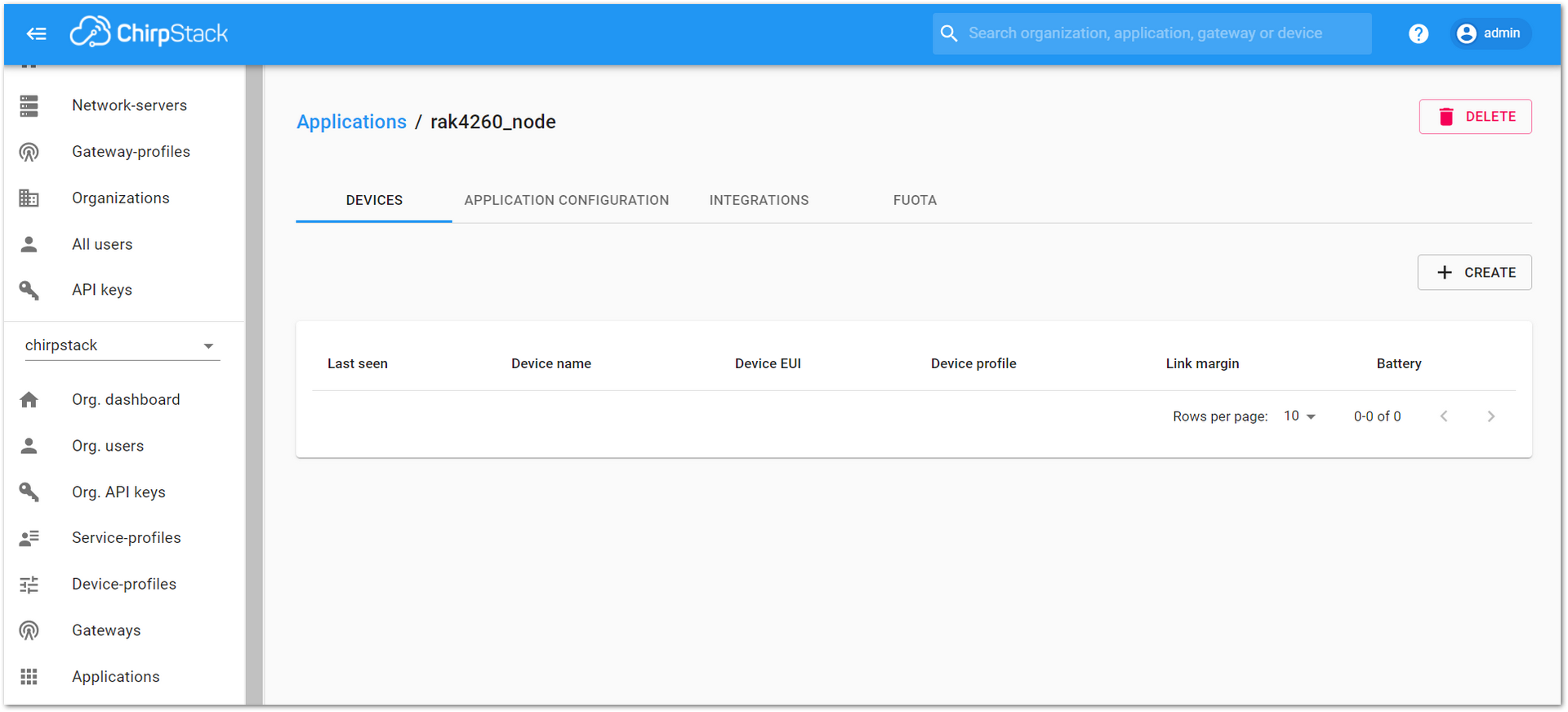 Figure 1: Device tab of an Application
- Inside the “DEVICES” tab, create a new device (LoRa node) by clicking on the “+ CREATE” button.
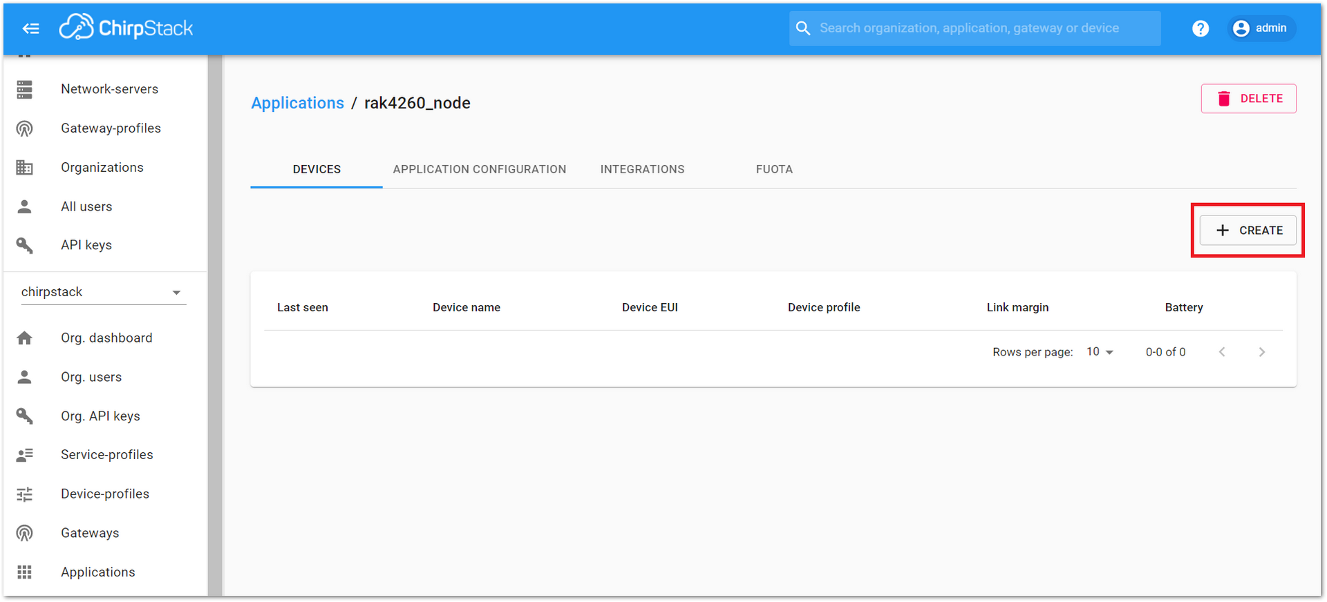 Figure 1: Add a new device at the Devices tab
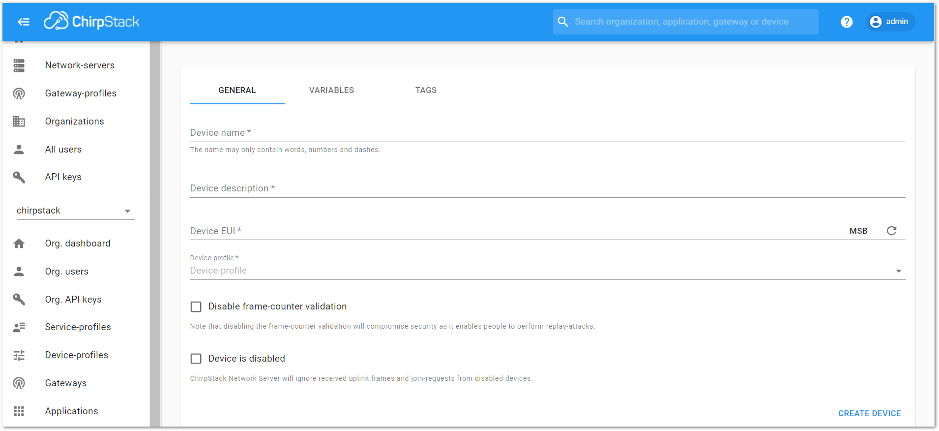 Figure 1: New device registration form
- Fill in the parameters requested as appears in Figure 30:
- Device name and Device description: These are just descriptive texts.
- Device EUI: This interface allows you to generate a Device EUI automatically by clicking the icon highlighted in red in Figure 31. You can also add a specific Device EUI directly in the form.
- Device-profile: To join in OTAA mode, select “device_profile_otaa” or "device_profile_abp" to join in ABP mode.
ChirpStack doesn’t support AS923 in ABP mode.
- Press the “CREATE DEVICE” button at the bottom of this page to finish the device registration.
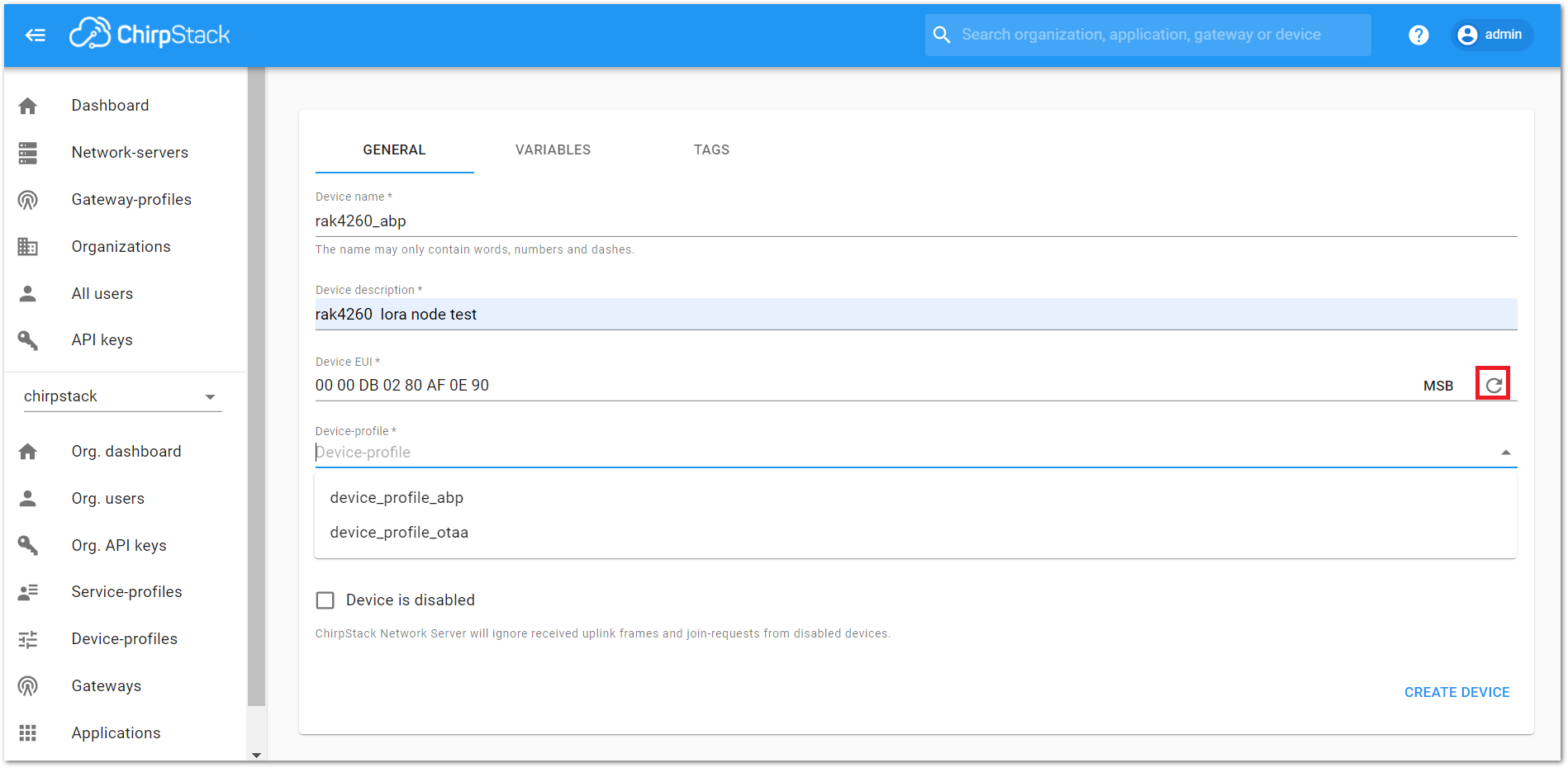 Figure 1: Generate a new Device EUI in the device registration form
LoRaWAN Join Mode
The LoRaWAN specification defines that to join a LoRaWAN network, each end-device has to be personalized and activated. Activation can be done either via Over-The-Air-Activation (OTAA) or via Activation-By-Personalization (ABP). In OTAA, the end-device previously personalized is activated when is deployed or reset. In ABP, personalization and activation are done as a single step.
OTAA Mode
Configure the OTAA Mode on the Platform
- If you have selected “device_profile_otaa”, then after the device is created, an “Application Key” must be also created for this device.
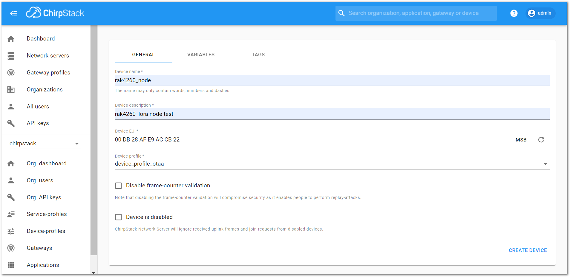 Figure 1: Choosing OTAA mode in the device registration form
- A previously created “Application Key” can be entered here, or a new one can be generated automatically by clicking the icon highlighted in red.
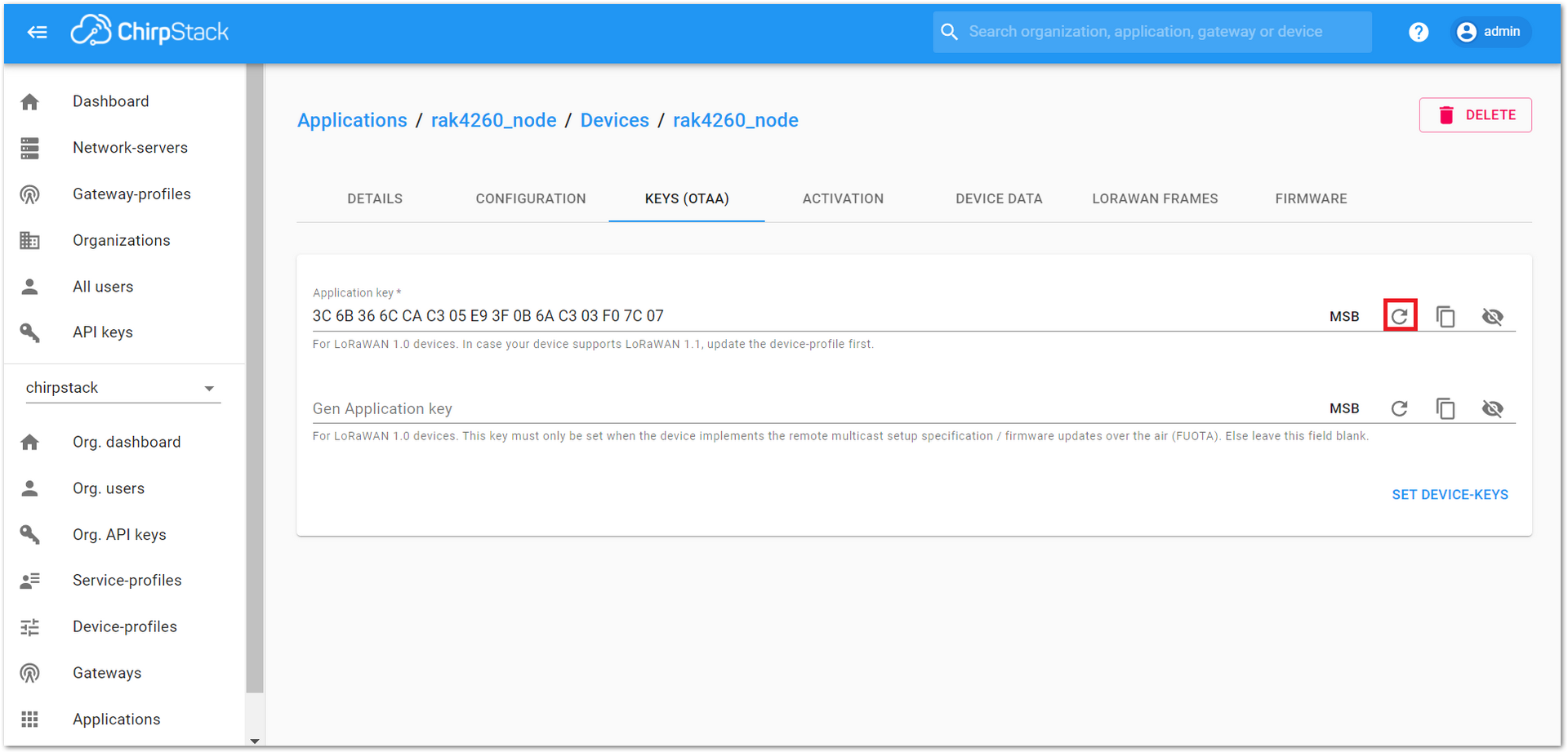 Figure 1: Application Key for the OTAA mode in the device registration form
- Once the Application Key is added to the form, the process can be finalized by clicking the “SET DEVICE-KEYS” button.
- As shown in Figure 34, a new device should be listed in the “DEVICES” tab. The most important parameters, such as the “Device EUI”, are shown in the summary.
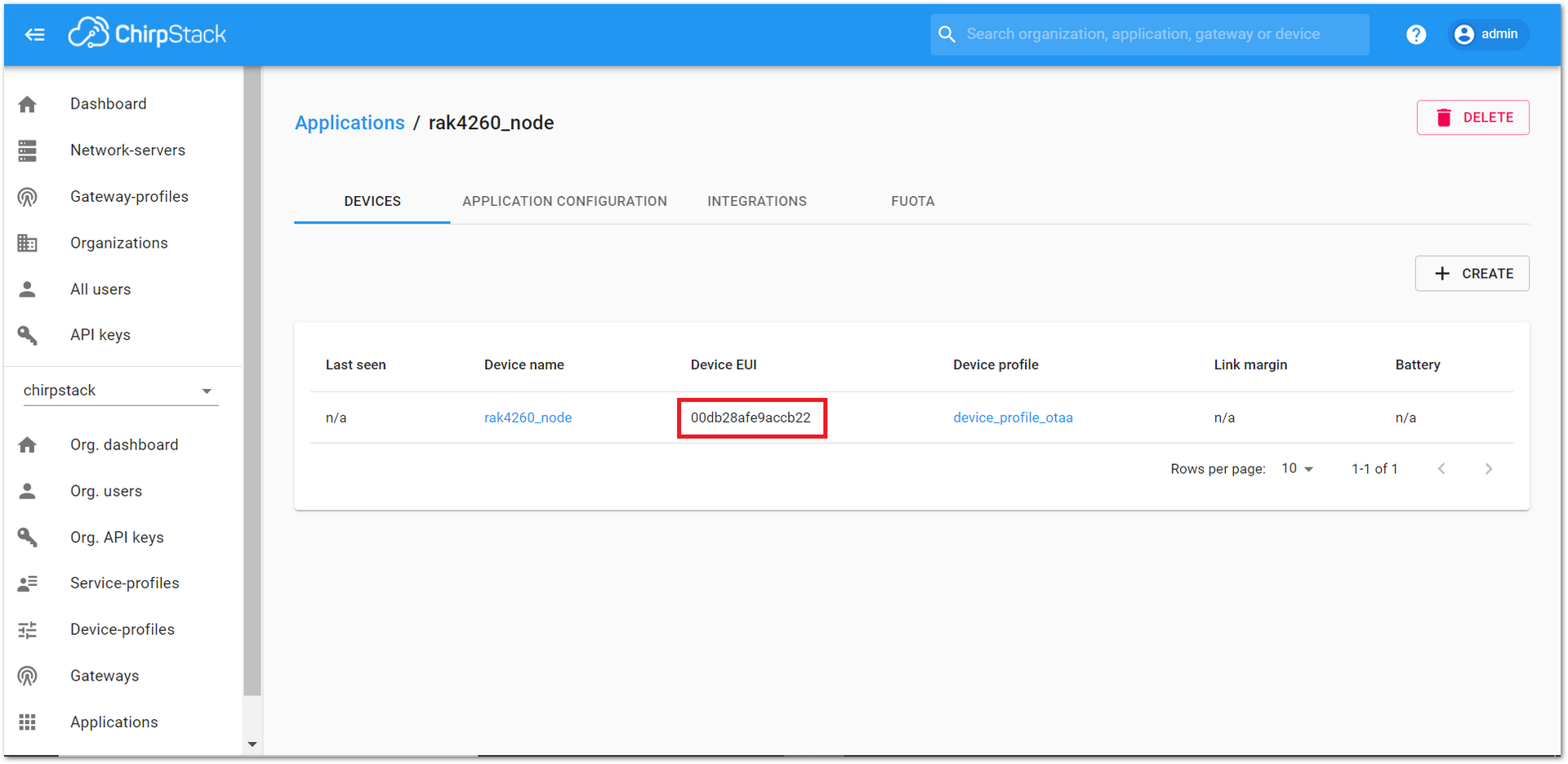 Figure 1: New crated device listed in the DEVICES tab
- To end the process, it is a good practice to review that the Application Key” is properly associated with this device. The “Application Key” can be verified in the “KEYS(OTAA)” tab.
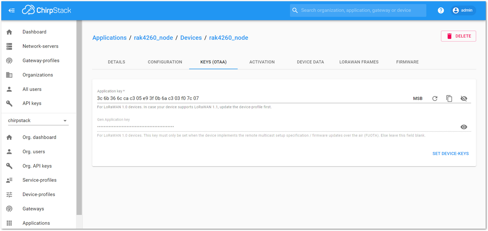 Figure 1: Application Key associated to the new device
Standard OTAA mode requires the Device EUI, Application Key, and the Application EUI. But in ChirpStack’s implementation, only Device EUI and the Application Key are mandatory. The Application EUI is not required and is not recorded in the Application tab.
ABP Mode
Configure the ABP Mode on the Platform
During the registration of a new device, if “device_profile_abp” is selected, then the ChirpStack platform will assume that this device will join the LoRaWAN network using the ABP mode.
- Fill in the parameters requested as appears in Figure 36:
- Device name and Device description: These are just descriptive texts.
- Device EUI: You can also add a specific Device EUI directly in the form.
- Once these parameters are filled, click the “CREATE DEVICE” button.
Check the Disable frame-counter validation to prevent the node-side counting the frame starting from zero after the node is powered on during the test, and the server cannot synchronize the node-side counting, causing the transmission to fail.
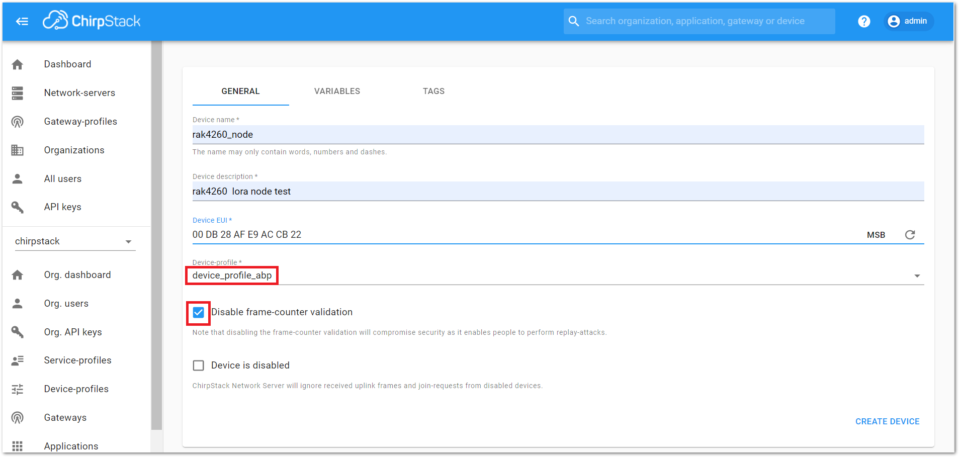 Figure 1: ChirpStack Console, configuring a device in ABP mode
After selecting the ABP mode, the following parameters appear in the “ACTIVATION” tab, as shown in Figure 37.
- Device address
- Network session key
- Application session key
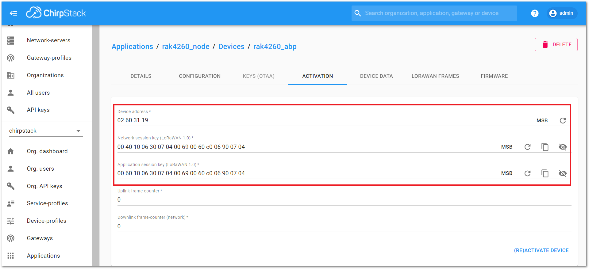 Figure 1: ChirpStack Console, parameters required for the ABP mode
- The parameters can be generated as random numbers by the platform or can be set with values. Once these parameters are filled properly, the process is completed by clicking on the “(RE)ACTIVATE DEVICE” button.
Capturing LoRaWAN Frames on ChirpStack Console
View LoRaWAN OTAA Frames
- Go to Applications -> rak4260-node -> Devices -> rak4260-node, then select the “LORAWAN FRAMES” tab.
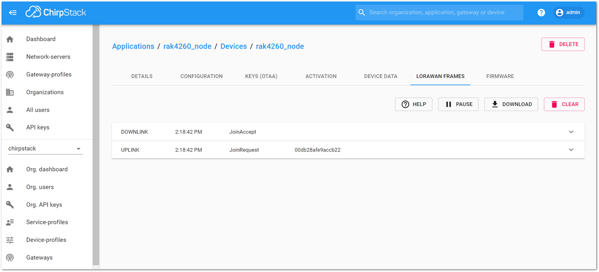 Figure 1: OTAA activation frame
- Go to Applications -> rak4260-node -> Devices -> rak4260-node, then select “DEVICE DATA” tab.
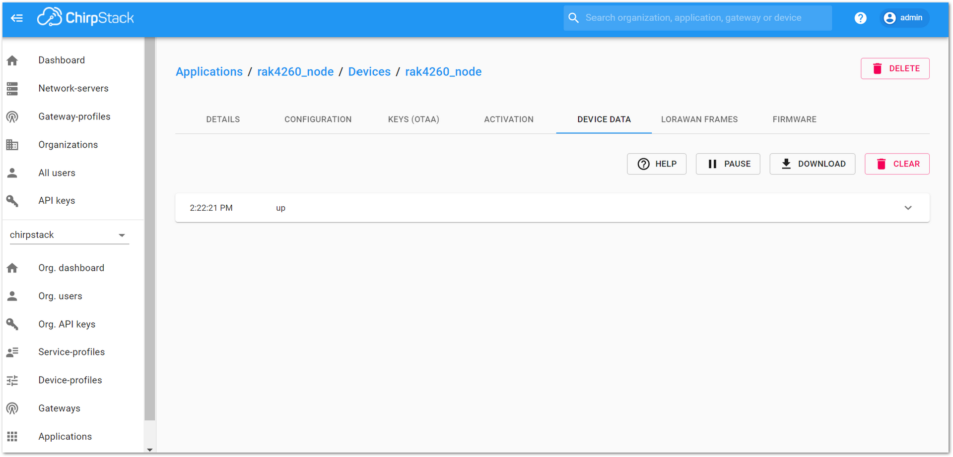 Figure 1: Device data OTAA frame
View LoRaWAN ABP Frames
- Go to Applications -> rak4260-node -> Devices -> rak4260-abp, then select the “LORAWAN FRAMES” tab.
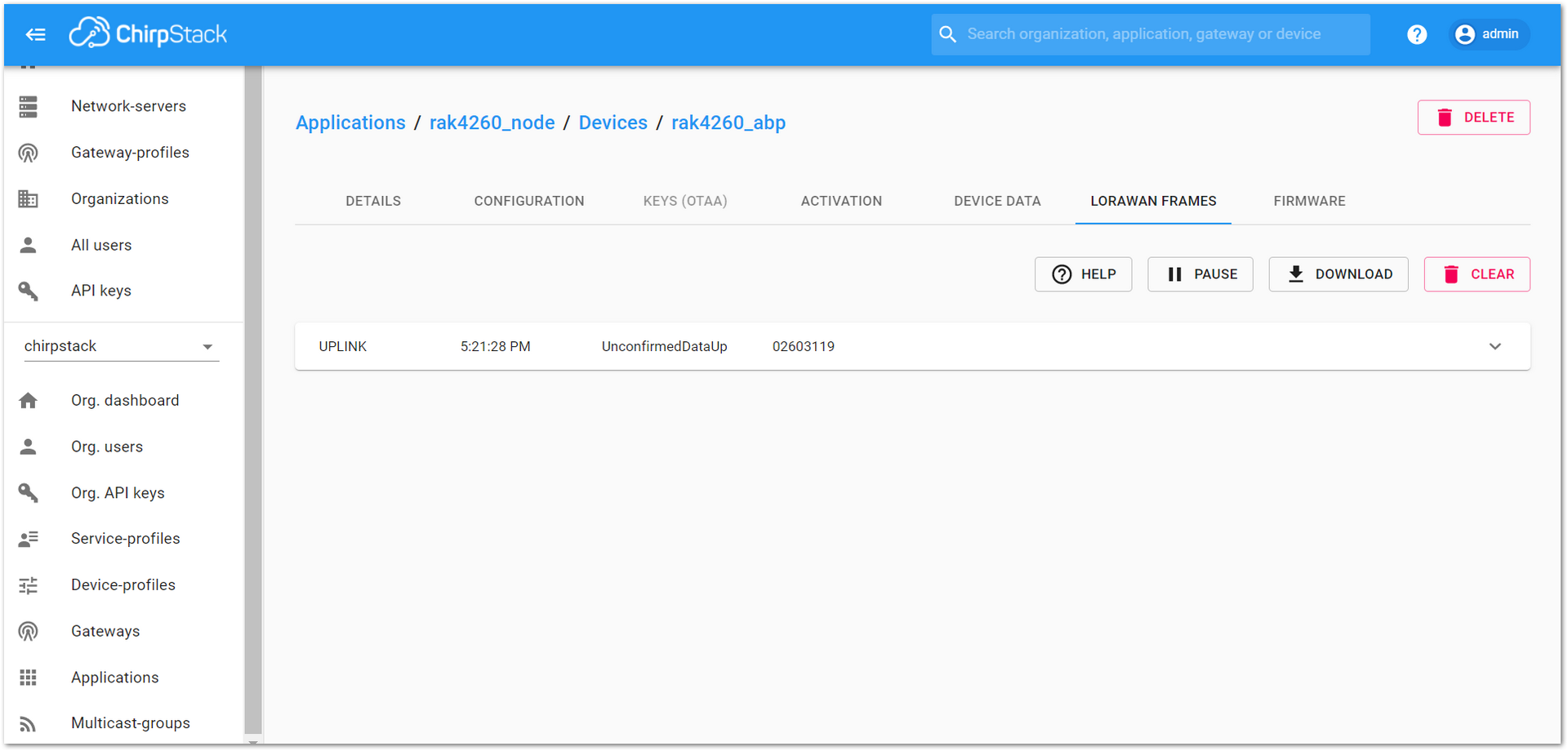 Figure 1: LoRaWAN ABP frame
- Go to Applications -> rak4260-node -> Devices -> rak4260-abp, then select “DEVICE DATA” tab.
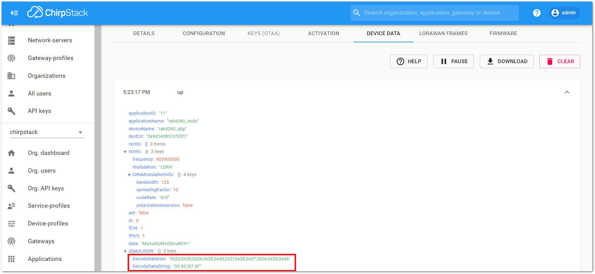 Figure 1: Device data ABP frame
Miscellaneous
Firmware Upgrade Through DAPLink
Refer to the RAKDAP1 Flash and Debug Tool guide in the Accessories Category.
