RAK811 Breakout Board Quick Start Guide
Prerequisites
Before proceeding with the installation and setup guide for the RAK811 Breakout Board, ensure you have the following necessary items prepared:
Hardware Tools
- RAK811 Breakout Board
- RAKDAP1 Flash and Debug Tool
- Gateway in Range for Testing
- Jumper Wires
- 3.3 V Battery Power Supply
- A Windows/Mac OS/Linux Computer
Software Tools
The bootloader for the RAK811 Breakout Board is pre-installed during manufacturing, so flashing the bootloader is not required. If you find the bootloader of your RAK811 Breakout Board to be damaged, contact our support team through the RAKwireless forum. For instructions on how to upgrade the firmware of the device, refer to the miscellaneous section of this document.
Package Inclusions
- 1 pc - RAK811 Breakout Board (chipset pre-soldered on the board)
- 1 pc - LoRa Antenna
Product Configuration
Connect the RAK811 Breakout Board
The RAK811 Breakout Board can be configured using AT commands via the UART interface. To connect the RAK811 to a PC's USB port, you need a USB to UART TTL adapter and a serial terminal tool. It is highly recommended to use the RAK Serial Port Tool, which allows you to easily send AT commands and view the corresponding replies from the console output.
Before powering the RAK811 Breakout Board, install the LoRa antenna first. Failure to do so may result in damage to the board.
- Figure 1 shows the Pinout Diagram of the Board and Figure 2 shows how to connect the RAK811 Breakout Board to the RAKDAP1.
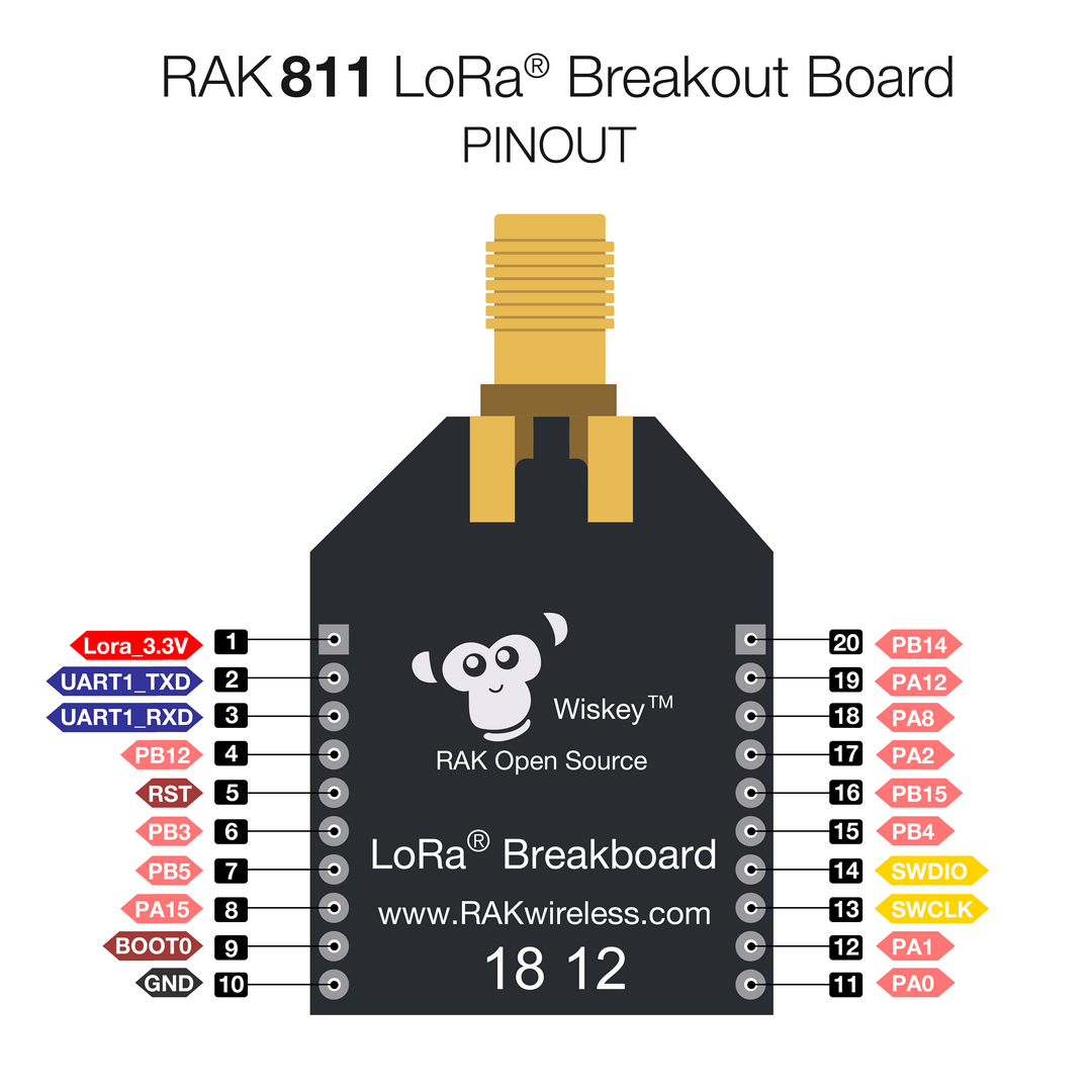 Figure 1: RAK811(H) Breakout Board Pinout Diagram
 Figure 1: RAKDAP1 to RAK811 Breakout Board Connection
- Connect your RAKDAP1 Flash and Debug Tool to your Windows machine. Then, open the RAK Serial Port Tool and select the correct COM port.
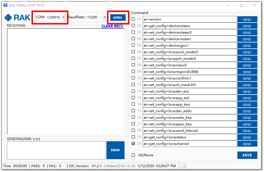 Figure 1: Correct Port Number and Correct Baud rate
Connecting to The Things Stack (TTN V3)
This section will show how to connect the RAK811 Breakout Board to The Things Stack (TTN V3) platform.
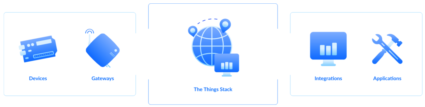 Figure 1: The Things Stack diagram
As shown in Figure 4, The Things Stack is an open source LoRaWAN Network Server suitable for global, geo-distributed public and private deployments as well as for small, local networks. The architecture follows the LoRaWAN Network Reference Model for standards compliancy and interoperability. This project is actively maintained byThe Things Industries.
LoRaWAN is a protocol for low-power wide-area networks. It allows for large scale Internet of Things deployments where low-powered devices efficiently communicate with Internet-connected applications over long range wireless connections.
The RAK811 Board can be part of this ecosystem as a device, and the objective of this section is to demonstrate how simple it is to send data to The Things Stack using the LoRaWAN protocol. To achieve this, the RAK811 Board must be located inside the coverage of a LoRaWAN gateway connected to The Things Stack server.
Registration to TTN and Creating LoRaWAN Applications
- Visit the The Things Network platform and choose a cluster, as shown in Figure 5. The Things Industries periodically adds more clusters, so select the one closest to your location. For this guide, Europe 1 is selected.
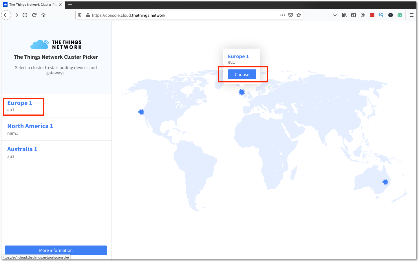 Figure 1: Select Cluster in TTN V3
- Log in using your existing TTN V2 credentials. If you don’t have an account, create one.
To register as a new user on TTN, click on Login with The Things ID, then select Register on the next page, as shown in Figures 6 and 7. Fill in all the required details and activate your account.
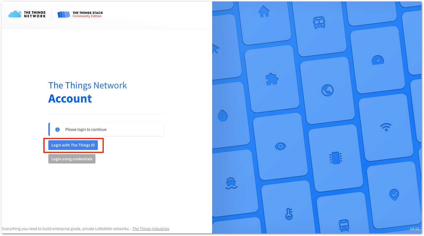 Figure 1: Log in using TTN account
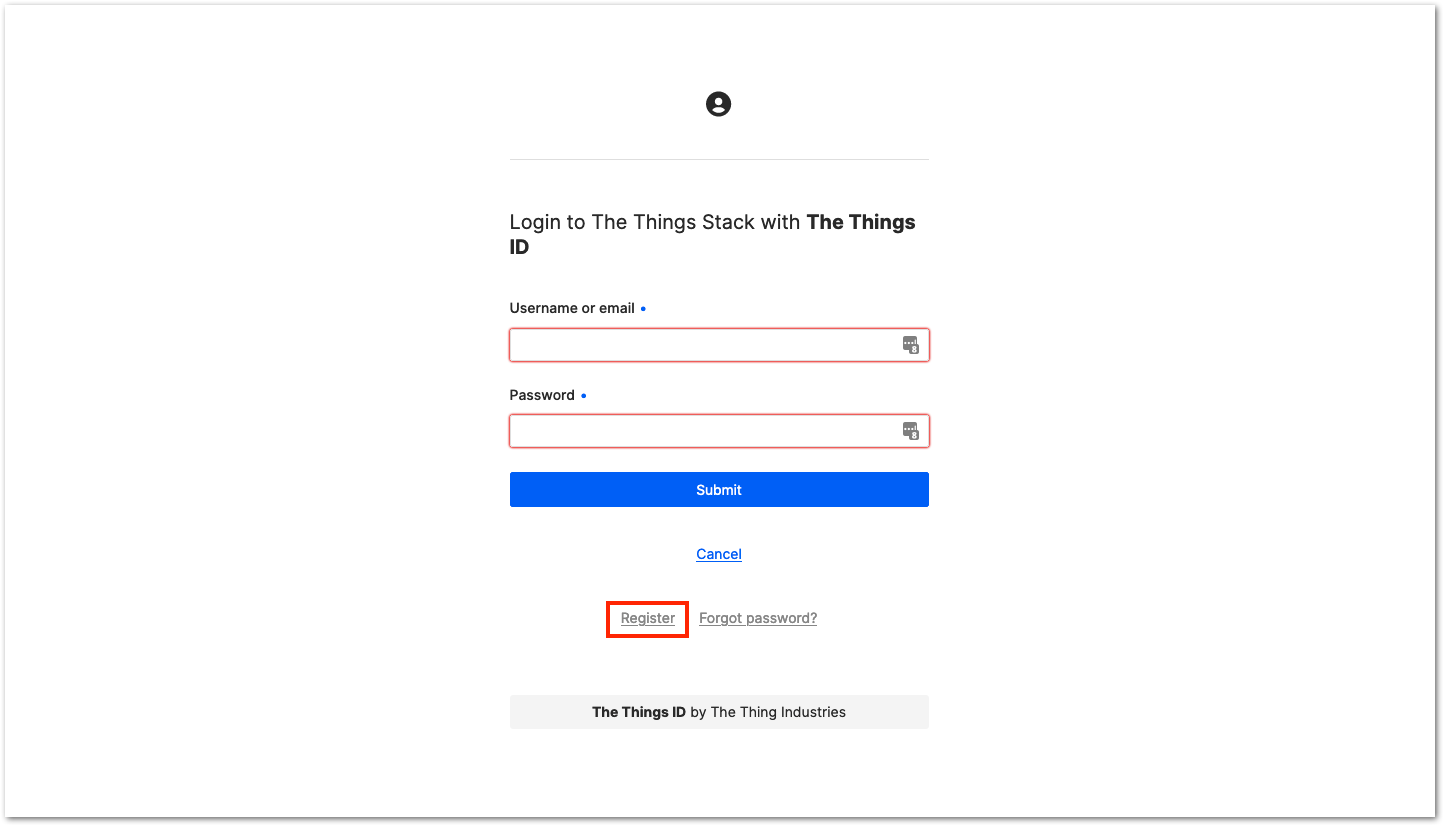 Figure 1: Registration of new account
- After creating an account, log in to the platform using your username/email and password, then click Submit, as shown in Figure 8.
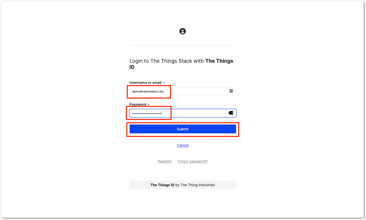 Figure 1: Log in to TTN platform
- Click Authorize to proceed.
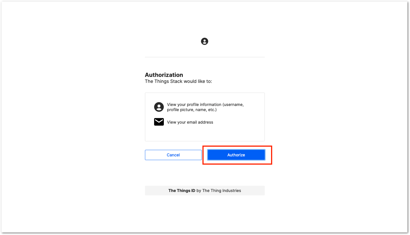 Figure 1: Authorization to TTN
- Click Create an application.
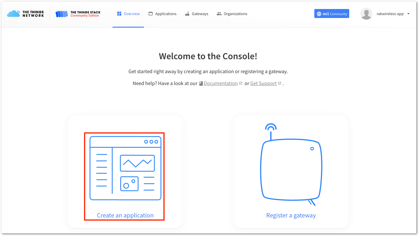 Figure 1: Create TTN application for your LoRaWAN devices
- To register an application, first input the specific details and required information about your application, then click Create application.
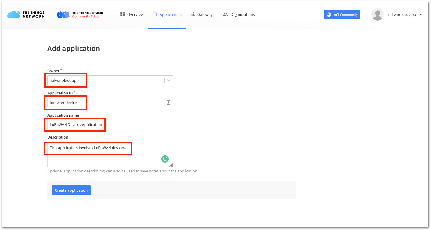 Figure 1: Details of the TTN application
- Add end devices to your The Things Stack application. The LoRaWAN specification requires that each end device be personalized and activated. Activation can be done through either Over-The-Air Activation (OTAA) or Activation By Personalization (ABP).
Ensure that you are within the coverage of a LoRaWAN gateway registered to The Things Stack (TTN V3). Without coverage from a registered LoRaWAN gateway, you will not be able to activate any devices that you register in your application.
RAKwireless offers LoRaWAN gateways that can be connected to The Things Stack (TTN V3) if there is no LoRaWAN gateway coverage available in your location.
The Things Stack OTAA Device Registration
- To start adding an OTAA end device, click + Add end device, as shown in Figure 12.
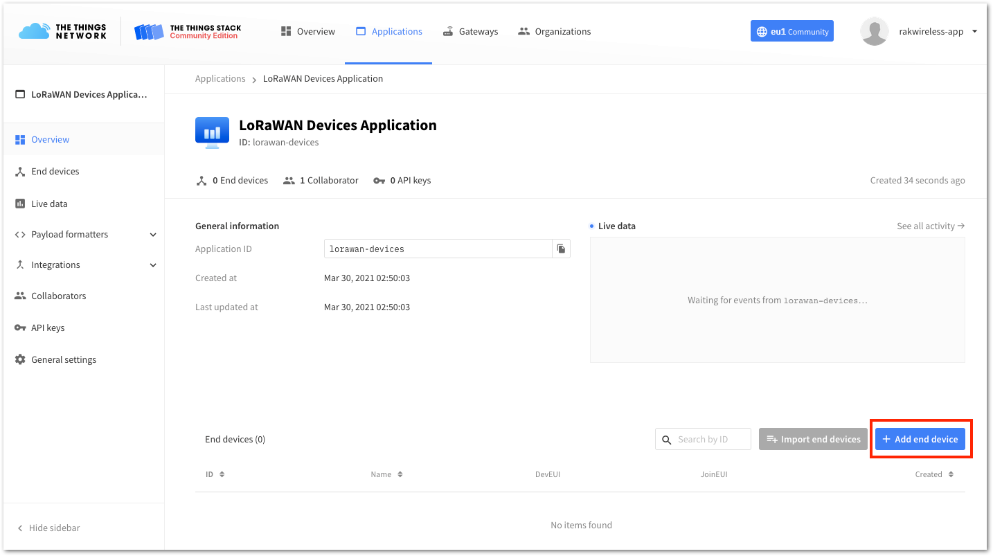 Figure 1: Add end device
- Click Manually, then configure the activation method by selecting Over The Air Activation (OTAA) and a compatible LoRaWAN version. Finally, click the Start button, as shown in Figure 13 and Figure 14.
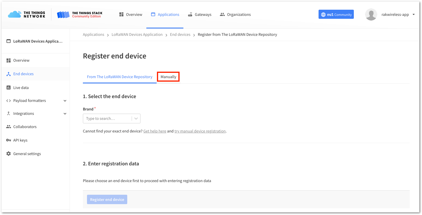 Figure 1: Manually register device to The Things Stack
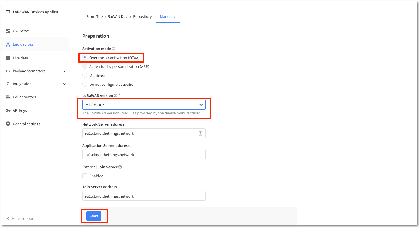 Figure 1: Device activation configuration
- Enter a unique End Device ID and EUIs (DevEUI and AppEUI). Optionally, provide an End Device Name and End Device Description. Finally, click Network Layer Settings to proceed to the next step.
-
Check if your module has a DevEUI on a sticker or a QR code that you can scan. Use this as the unique DevEUI for the device.
-
It is recommended to use meaningful End Device ID, End Device Name, and End Device Description that align with your device's purpose. The End Device ID
rak-deviceis used for illustration purposes only.
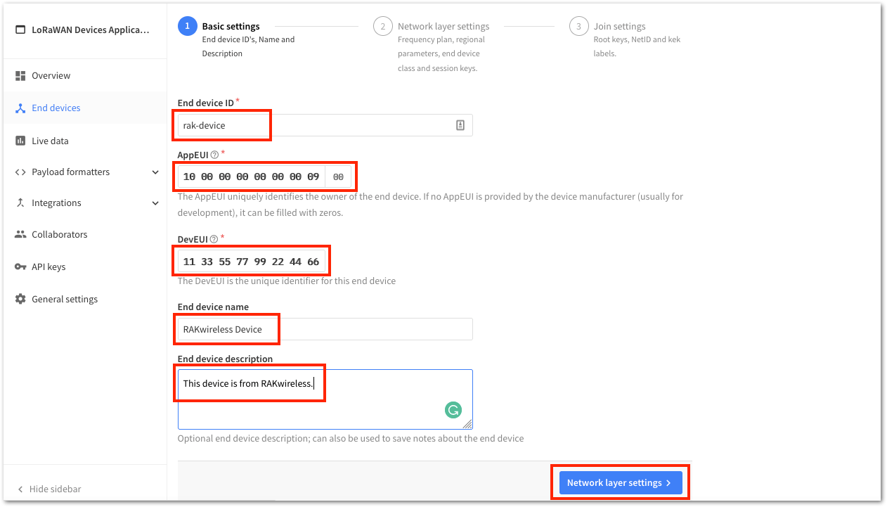 Figure 1: OTAA Device Information
- Set up the Frequency Plan, compatible Regional Parameter Version, and supported LoRaWAN Class. Then, click Join Settings to proceed.
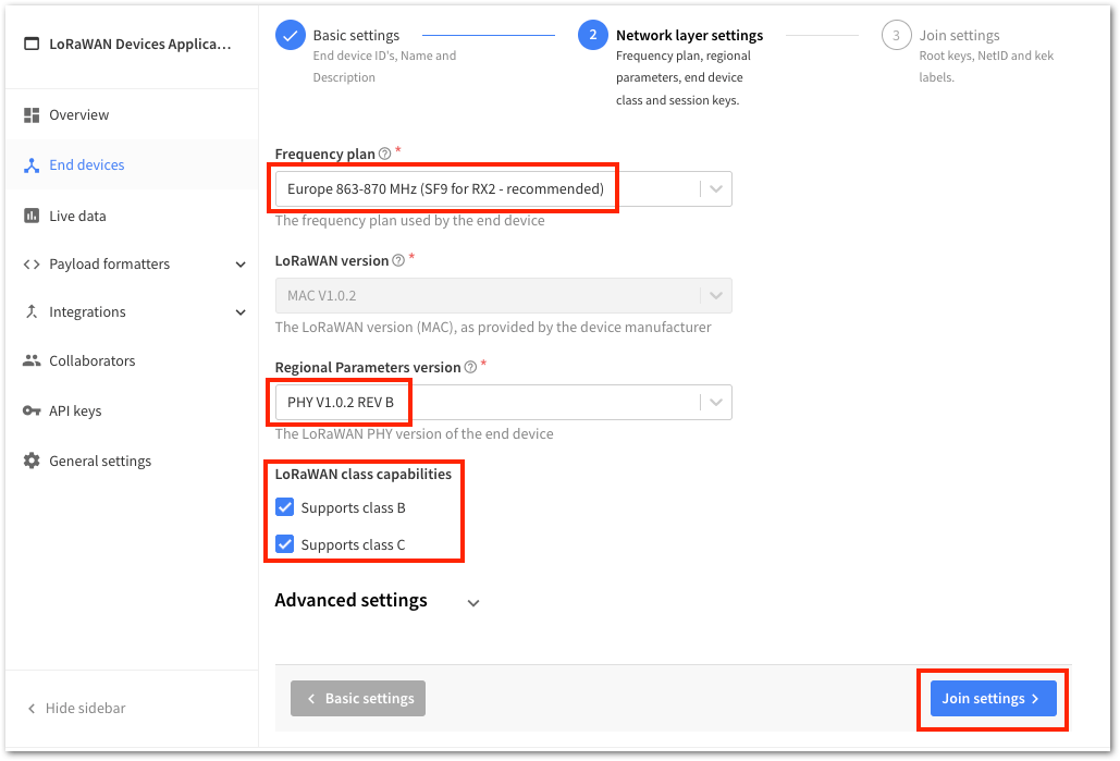 Figure 1: OTAA Configuration
- To obtain an AppKey, click the Generate button. Then, click Add End Device to complete the registration of your new device.
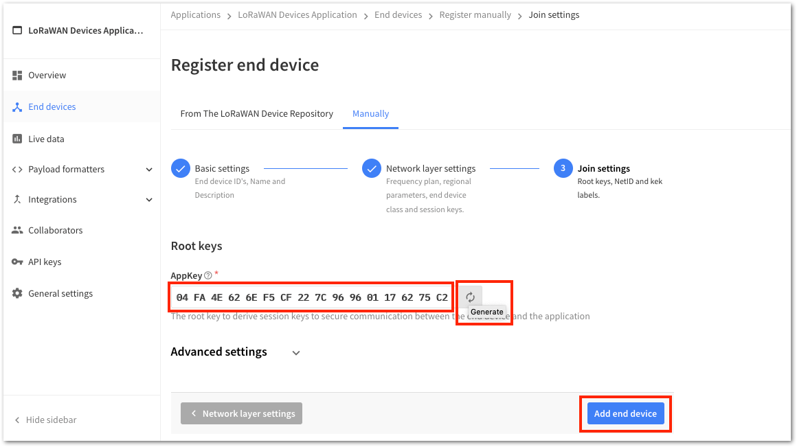 Figure 1: OTAA AppKey generation and device registration
You should now be able to see the device on The Things Stack console after you fully registered your device, as shown in Figure 18.
-
The AppEUI, DevEUI, and AppKey are the parameters required to activate your LoRaWAN end device via OTAA. For security reasons, the AppKey is hidden by default, but you can reveal it by clicking the Show button. You can also quickly copy these parameters using the Copy button.
-
The three OTAA parameters on The Things Stack device console are MSB by default.
-
These parameters are always accessible on the device console page, as shown in Figure 18.
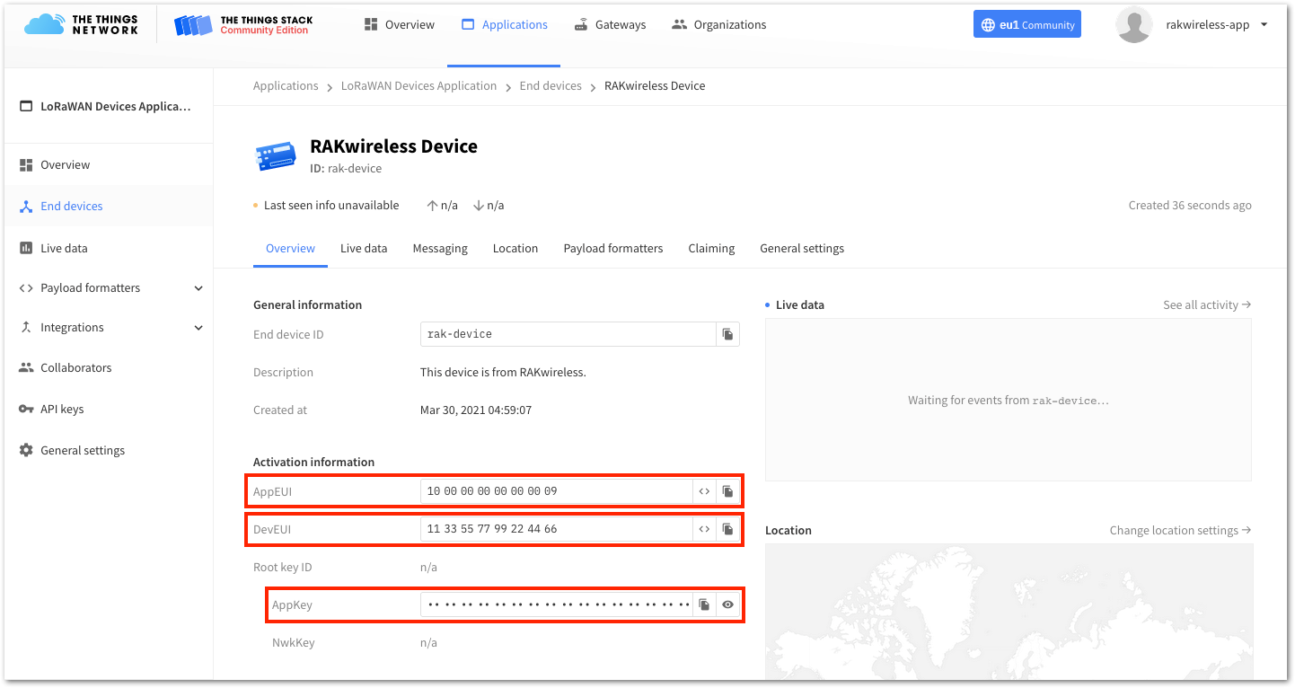 Figure 1: OTAA device successfully registered to The Things Stack
RAK811 OTAA Configuration for The Things Stack
The RAK811 Board supports a series of AT commands to configure its internal parameters and control the functionalities of the module. To set up the RAK811 Board to join The Things Stack using OTAA, start by connecting the RAK811 Board to the Computer (see Figure 1) and open the RAK Serial Port Tool. Wait for the communication to start. It is recommended to test the serial communication and verify the current configuration by sending either of these two AT commands:
at+set_config=device:restart
at+version
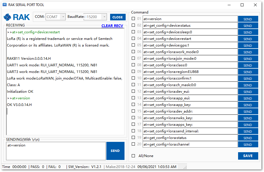 Figure 1: AT Command response
As an example, these are the list of the parameters you need to configure in RAK811:
- LoRa join mode: OTAA
- LoRa class: Class A
- LoRa region: EU868
- Device EUI: 1133557799224466
- Application EUI: 1000000000000009
- Application Key: 04FA4E626EF5CF227C969601176275C2
- Set the LoRa join mode to OTAA.
at+set_config=lora:join_mode:0
- Set the LoRa class to Class A.
at+set_config=lora:class:0
- Set the frequency/region to EU868.
- Refer in the RAK811 Breakout Board Datasheet for the list of supported frequencies.
at+set_config=lora:region:EU868
- Set the Device EUI.
at+set_config=lora:dev_eui:1133557799224466
- Set the Application EUI.
All zero value Application EUI at+set_config=lora:app_eui:0000000000000000 is not supported and will return error.
at+set_config=lora:app_eui:1000000000000009
- Set the Application Key.
at+set_config=lora:app_key:04FA4E626EF5CF227C969601176275C2
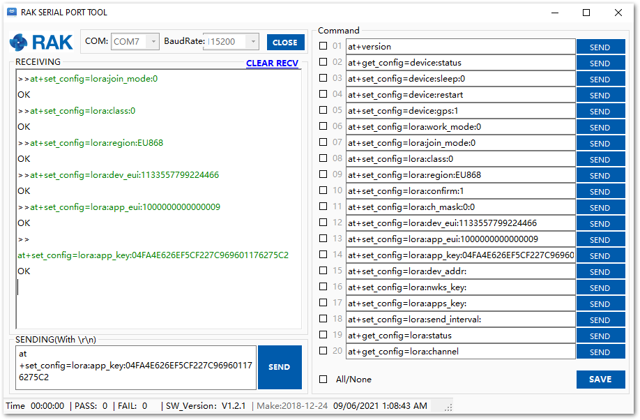 Figure 1: Configure LoRa Parameters
After configuring all the parameters, reset your RAK811 Board for saving the parameters.
- Join in OTAA mode.
at+join
After 5 or 6 seconds, if the request is successfully received by a LoRa gateway, then you should see the messages shown in Figure 21.
- Try to send a message from the RAK811 Board.
at+send=lora:2:1234567890
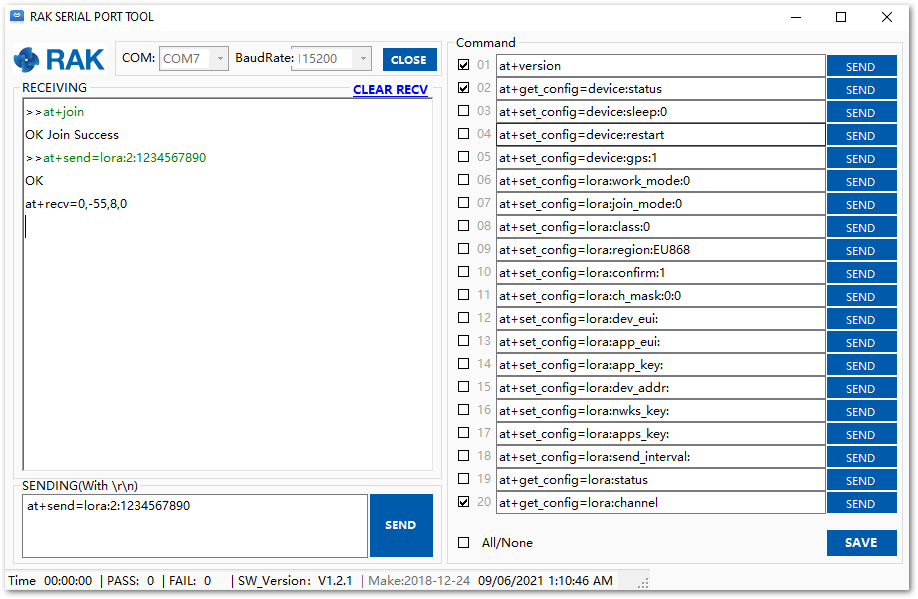 Figure 1: OTAA Test Sample Data Sent via RAK Serial Port Tool
You will see the data sent by the RAK811 Board on The Things Stack platform, as shown in Figure 22.
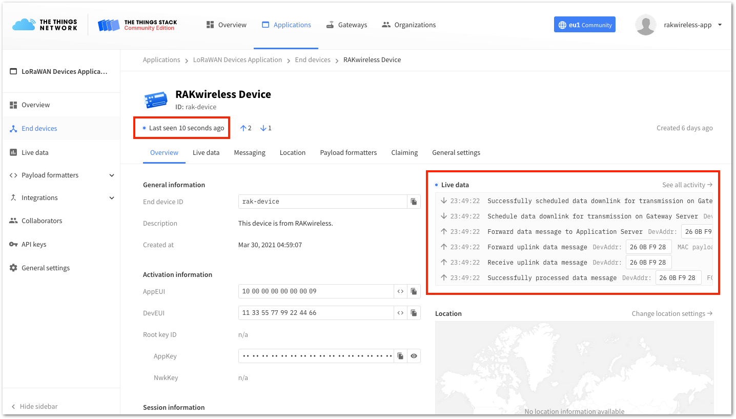 Figure 1: OTAA Test Sample Data Sent Viewed in The Things Stack
The Things Stack ABP Device Registration
- To register an ABP device, navigate to your application console and select the application where you want to add the device. Then, click + Add end device, as shown in Figure 23.
Figure 1: Add end device- To register the module, click Manually, then configure the activation method by selecting Activation By Personalization (ABP) and a compatible LoRaWAN version. Finally, click the Start button, as shown in Figure 24 and Figure 25.
Figure 1: Add end device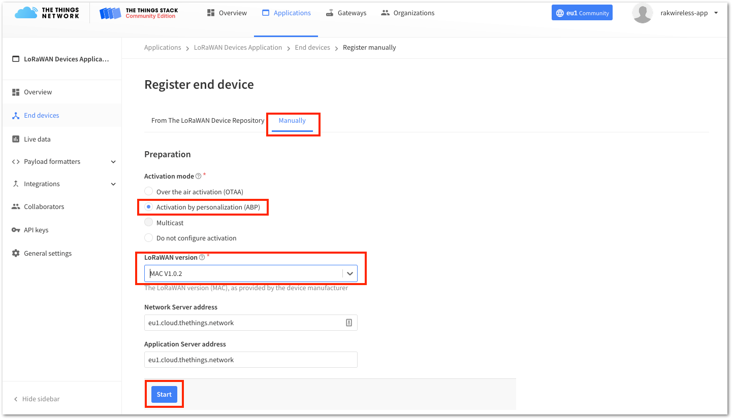 Figure 1: Manually register device to The Things Stack
- Enter a unique End Device ID and DevEUI. Optionally, provide an End Device Name and End Device Description for your device. Then, click Network Layer Settings to proceed to the next step.
-
Check if your module has a DevEUI on a sticker or QR code that you can scan. Use this as the device's unique DevEUI.
-
It is recommended to use meaningful End Device ID, End Device Name, and End Device Description that align with your device's purpose. The End Device ID
rak-device-abpis used for illustration purposes only.
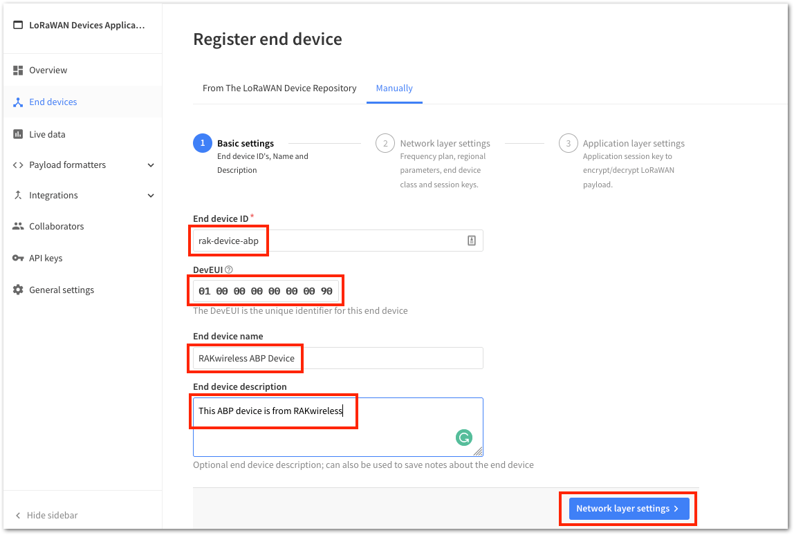 Figure 1: Device Information
- Set up the Frequency Plan, compatible Regional Parameter Version, and supported LoRaWAN Class. For an ABP device, generate the Device Address and NwkSKey (Network Session Key). Then, click Application Layer Settings to proceed.
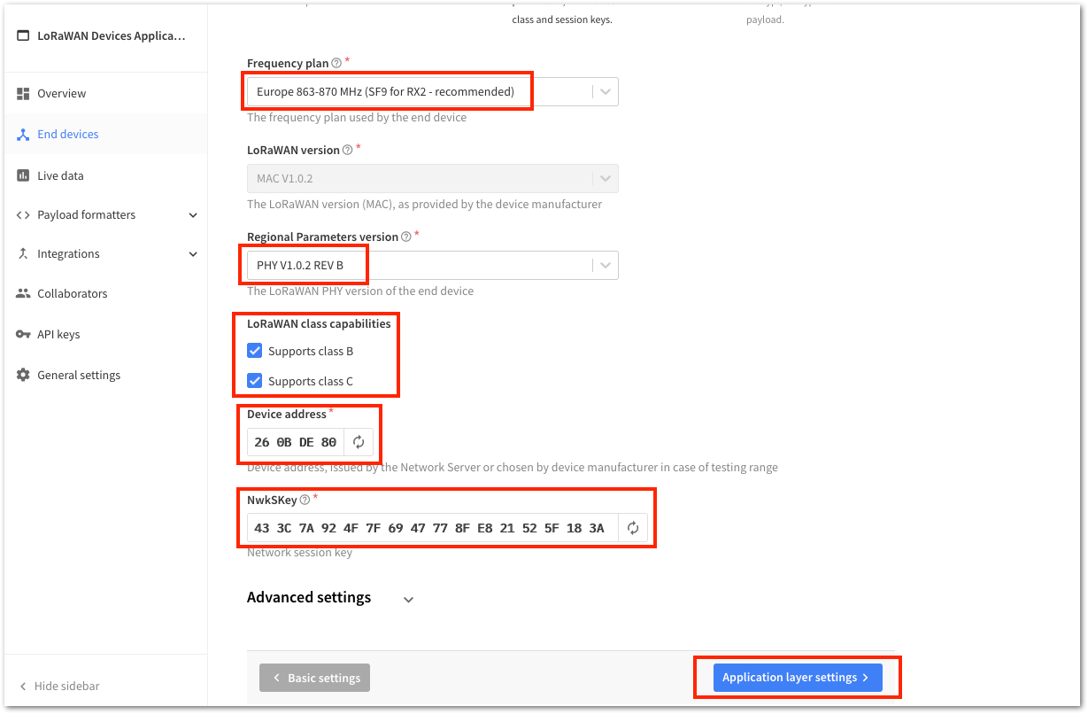 Figure 1: ABP Configuration in The Things Stack
- To obtain the AppSKey, click the Generate button. Then, click Add End Device to complete your new device registration.
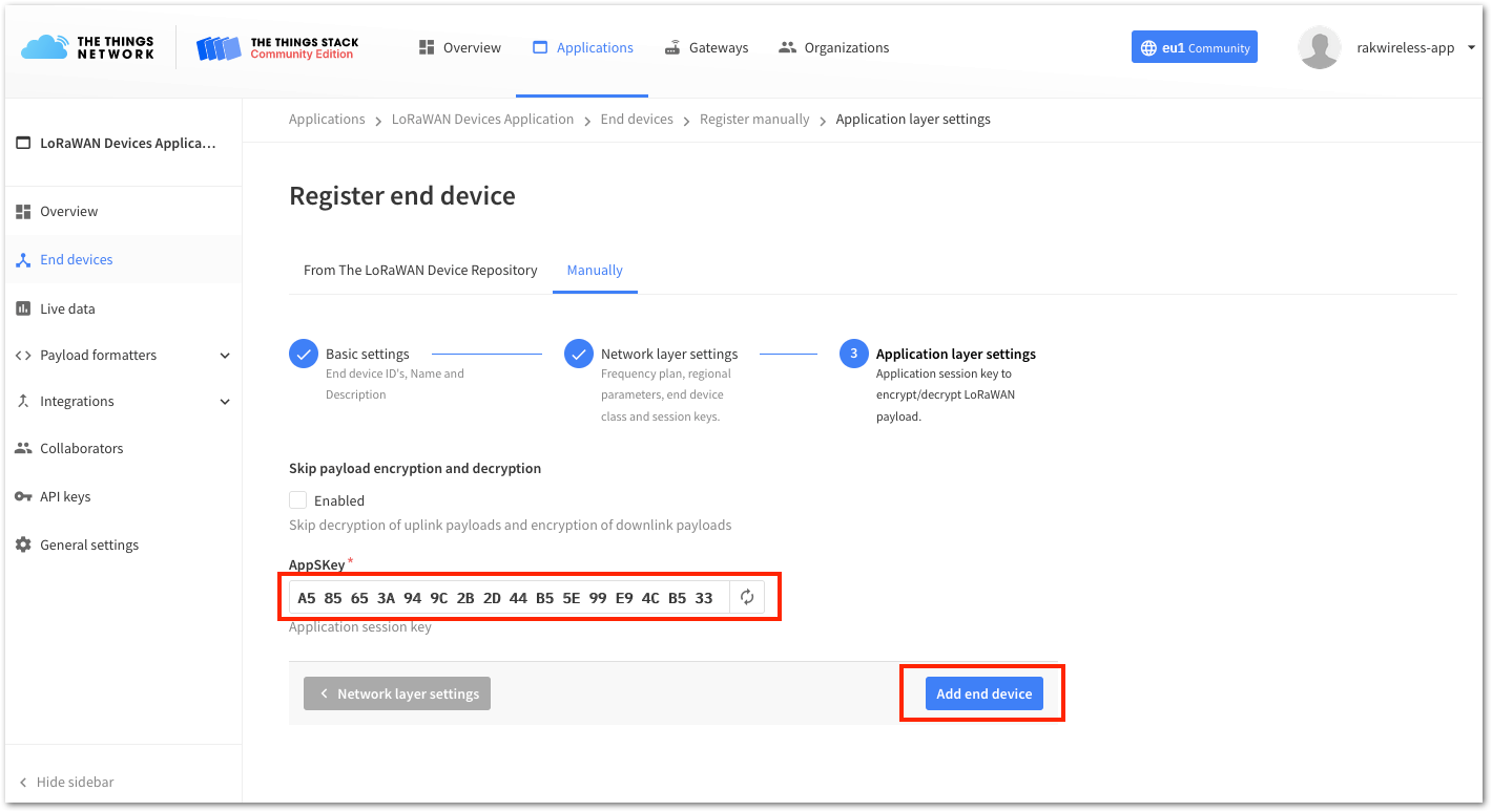 Figure 1: ABP Configuration in The Things Stack
You should now be able to see the device on The Things Stack console, as shown in Figure 29.
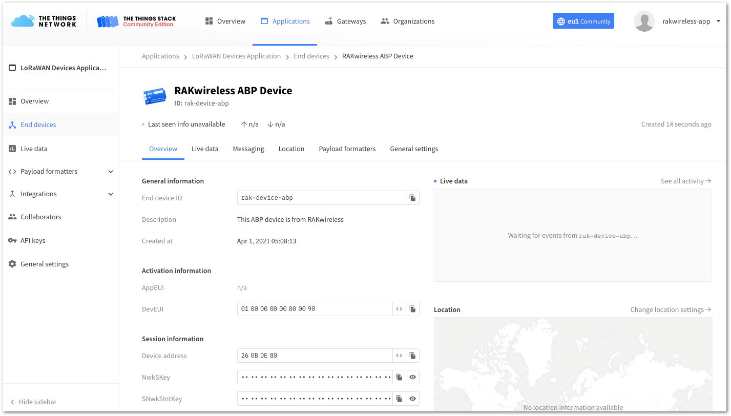 Figure 1: RAK811 registered at The Things Stack
RAK811 ABP Configuration for The Things Stack
To set up the RAK811 Board to join The Things Stack using ABP, start by connecting the RAK811 Board to the Computer (see Figure 1) and open the RAK Serial Port Tool. It is recommended to test the serial communication by sending either of these two AT commands:
at+set_config=device:restart
at+version
As an example, here is the list of parameters you need to configure in the RAK811:
- LoRa join mode: ABP
- LoRa class: Class A
- LoRa region: EU868
- Device address: 260BDE80
- Network Session Key: 433C7A924F7F6947778FE821525F183A
- Application Session Key: A585653A949C2B2D44B55E99E94CB533
- Set the LoRa join mode to ABP.
at+set_config=lora:join_mode:1
- Set the LoRa class to Class A.
at+set_config=lora:class:0
- Set the frequency/region to EU868.
- Refer in the RAK811 Breakout Board Datasheet for the list of supported frequencies.
at+set_config=lora:region:EU868
- Set the Device Address.
at+set_config=lora:dev_addr:260BDE80
- Set the LoRa Network Session Key.
at+set_config=lora:nwks_key:433C7A924F7F6947778FE821525F183A
- Set the LoRa Application Session Key.
at+set_config=lora:apps_key:A585653A949C2B2D44B55E99E94CB533
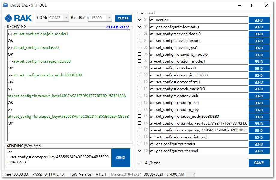 Figure 1: AT Command for ABP LoRa parameters via RAK Serial Port Tool
After configuring all the parameters, reset RAK811 Board for saving the parameters.
- Join in ABP mode.
at+join
In ABP mode of LoRaWAN, a device does not need to join a network before sending a LoRaWAN package. However, to maintain the consistency of the internal states of the RAK811 Board's firmware, it is still necessary to send the at+join command. In ABP mode, the firmware will reply almost immediately with an "OK".
- Try to send a data from the RAK811 to The Things Network in ABP mode.
at+send=lora:2:1234567890
You can see the data sent by the RAK811 Board on the The Things Stack device console Live data section and the Last seen info should be a few seconds ago.
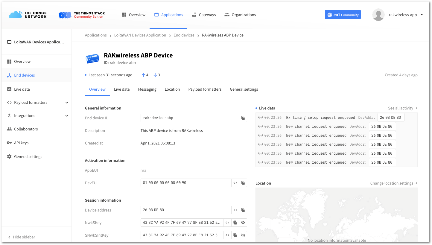 Figure 1: OTAA Test Sample Data Sent Viewed in The Things Stack
Connecting to ChirpStack
The ChirpStack or previously known as LoRaServer project provides open-source components for building LoRaWAN networks. To learn more about ChirpStack, visit their website.
You can use RAK811 Breakout Board to connect with ChirpStack according to the following steps:
In this document, it is assumed that you are using RAK Gateway and its built-in ChirpStack or RAK cloud testing ChirpStack. Also, the RAK Gateway with Chirpstack must be configured successfully.
-
Open the ChirpStack web interface that you want to connect to and log in with your credentials.
-
By default, there is already one or more items in this page. You can either use it or create a new item, but for this, create a new item by clicking the “CREATE” button.
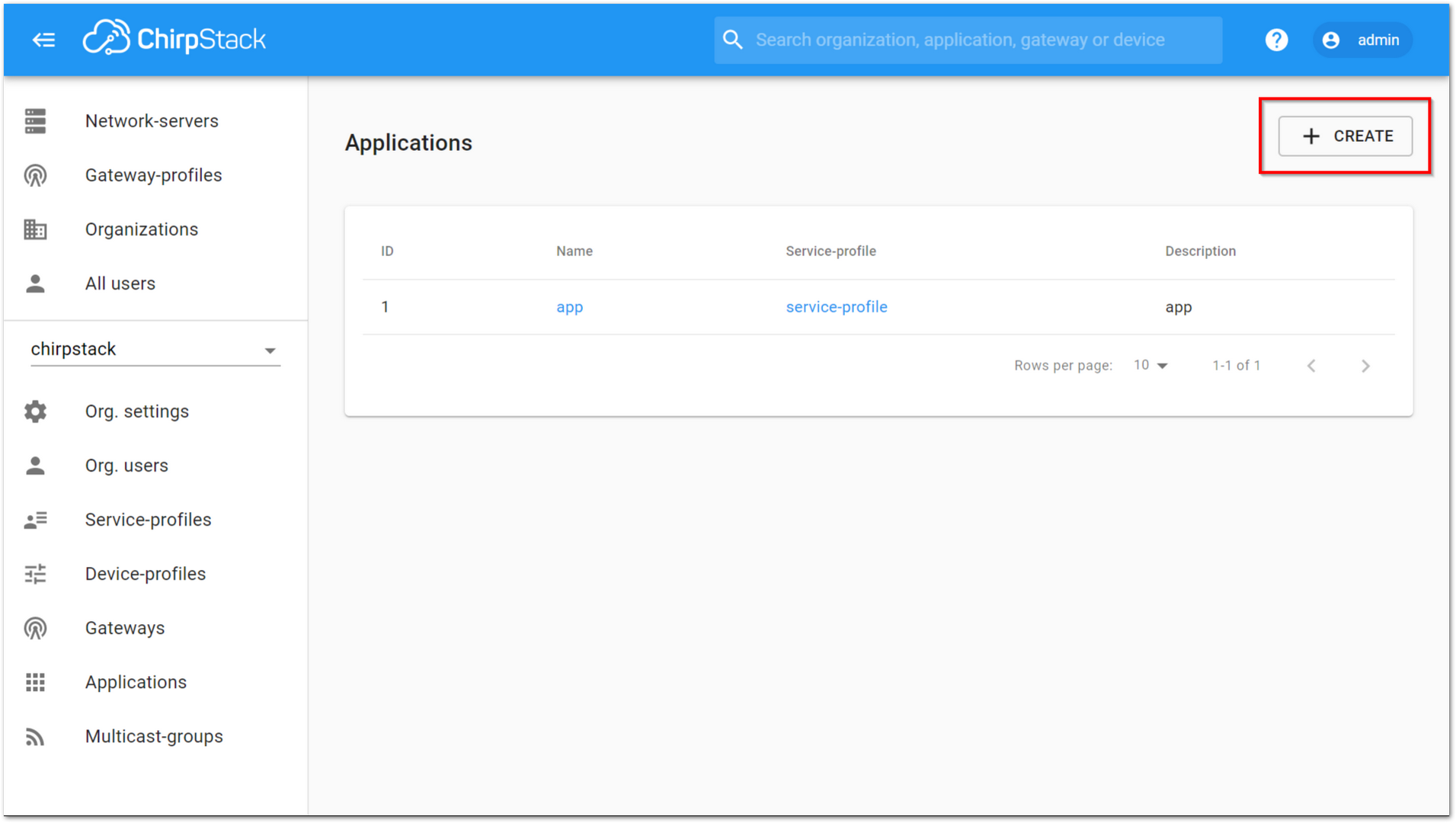 Figure 1: ChirpStack Applications
- Fill up the necessary information then Click CREATE APPLICATION.
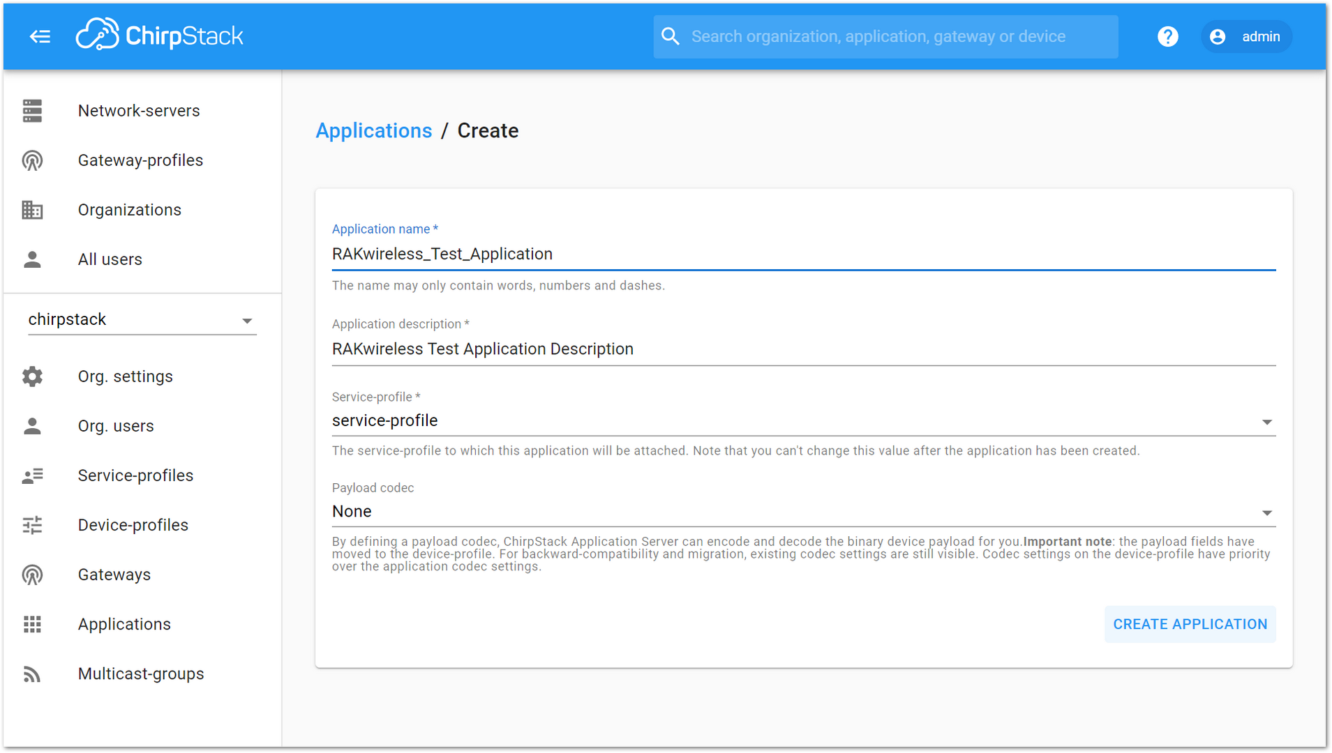 Figure 1: Create the Application
- Click the new item name RAKwireless_Test_Application:
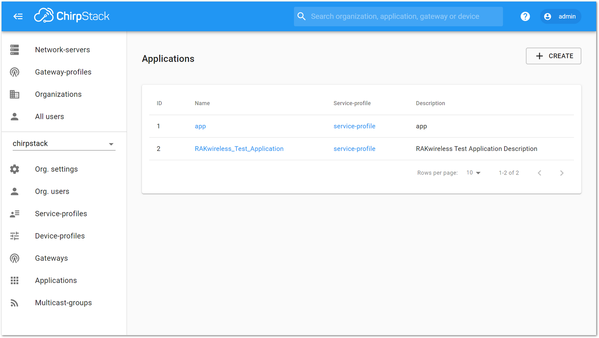 Figure 1: Applications page in ChirpStack
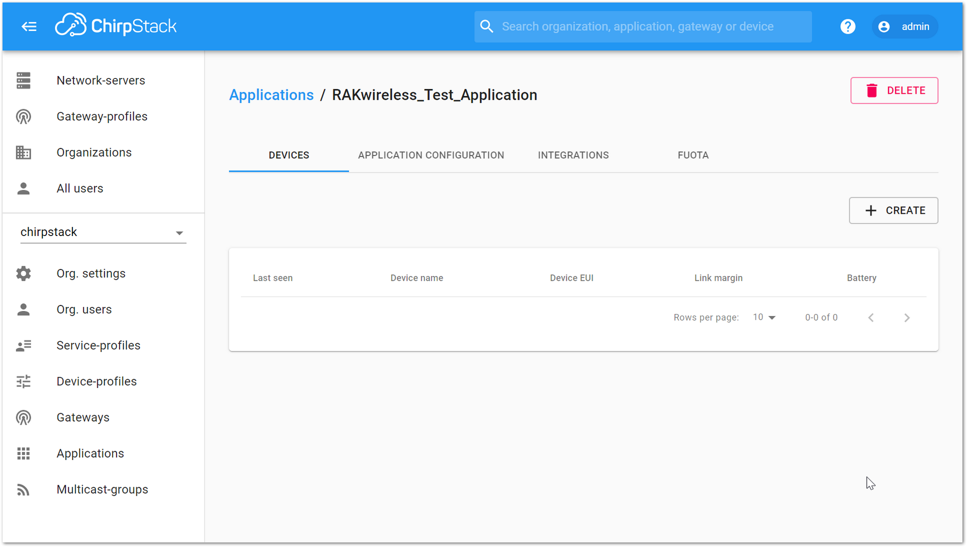 Figure 1: RAK811 Breakout Board Application
- Add a Node device into ChirpStack by clicking the “CREATE” button.
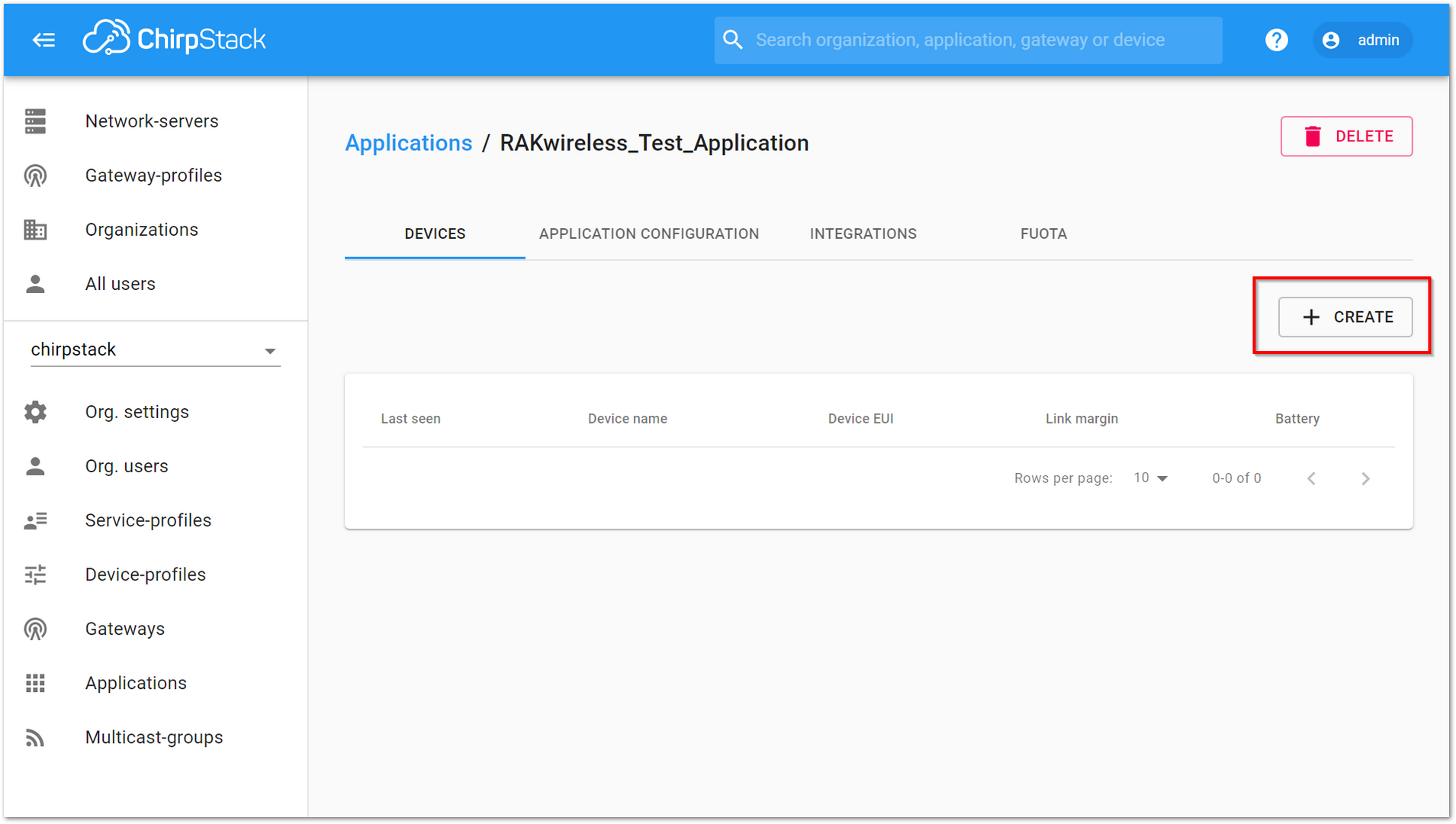 Figure 1: Add a Node Device
- Fill in the required fields. You can generate a Device EUI automatically by clicking the Device EUI icon, or manually enter the correct Device EUI in the edit box.
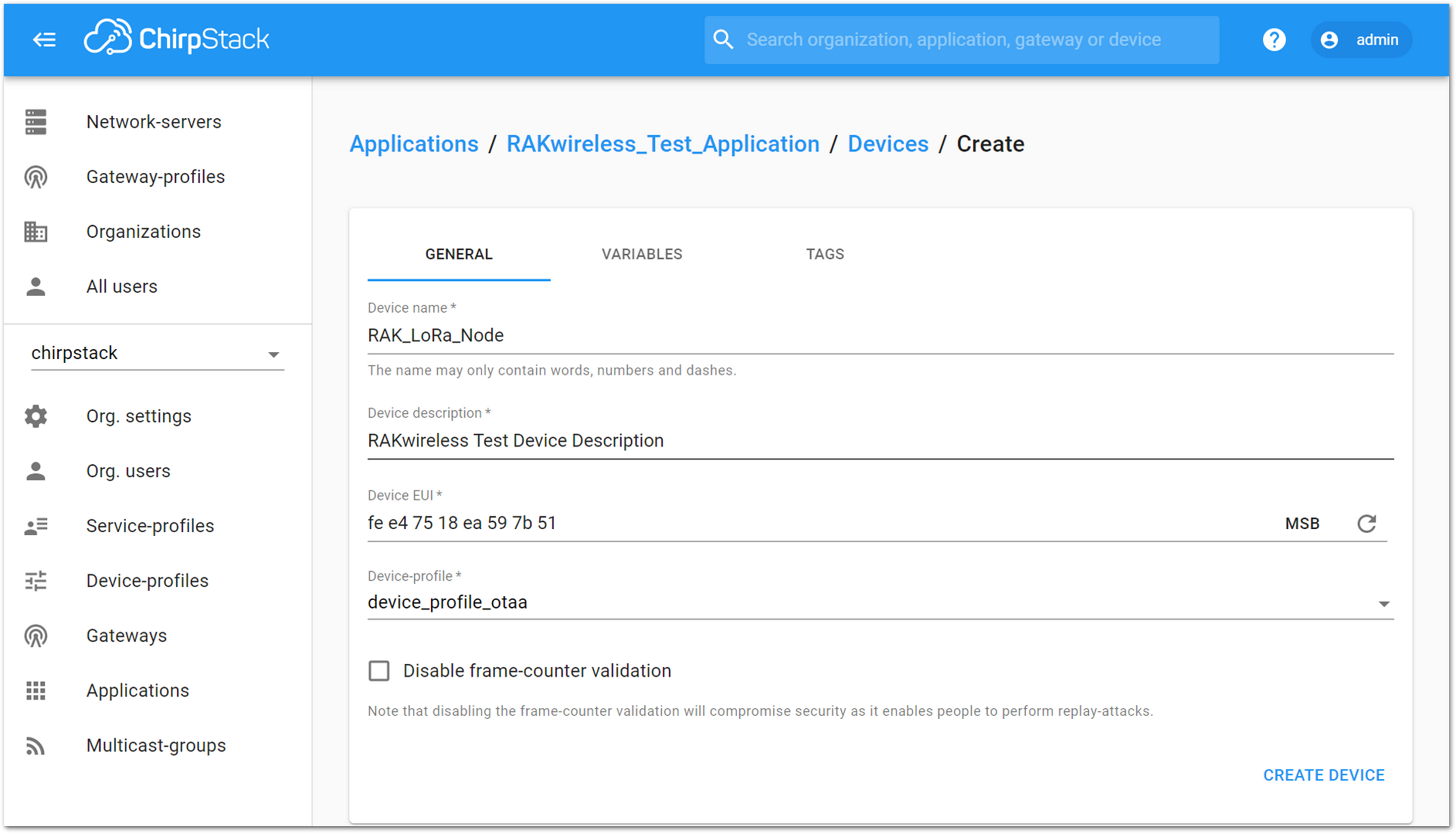 Figure 1: Fill the Device Parameters
- If you want to join in OTAA mode, select DeviceProfile_OTAA in the Device-profile item.
- If you want to join in ABP mode and CN470 frequency, select DeviceProfile_ABP_CN470 in the Device-Profile item.
- If you want to join in ABP mode and other frequencies except AS923 and CN470, select DeviceProfile_ABP in the Device-profile item.
OTAA Mode
- To join ChirpStack in OTAA mode, select DeviceProfile_OTAA.
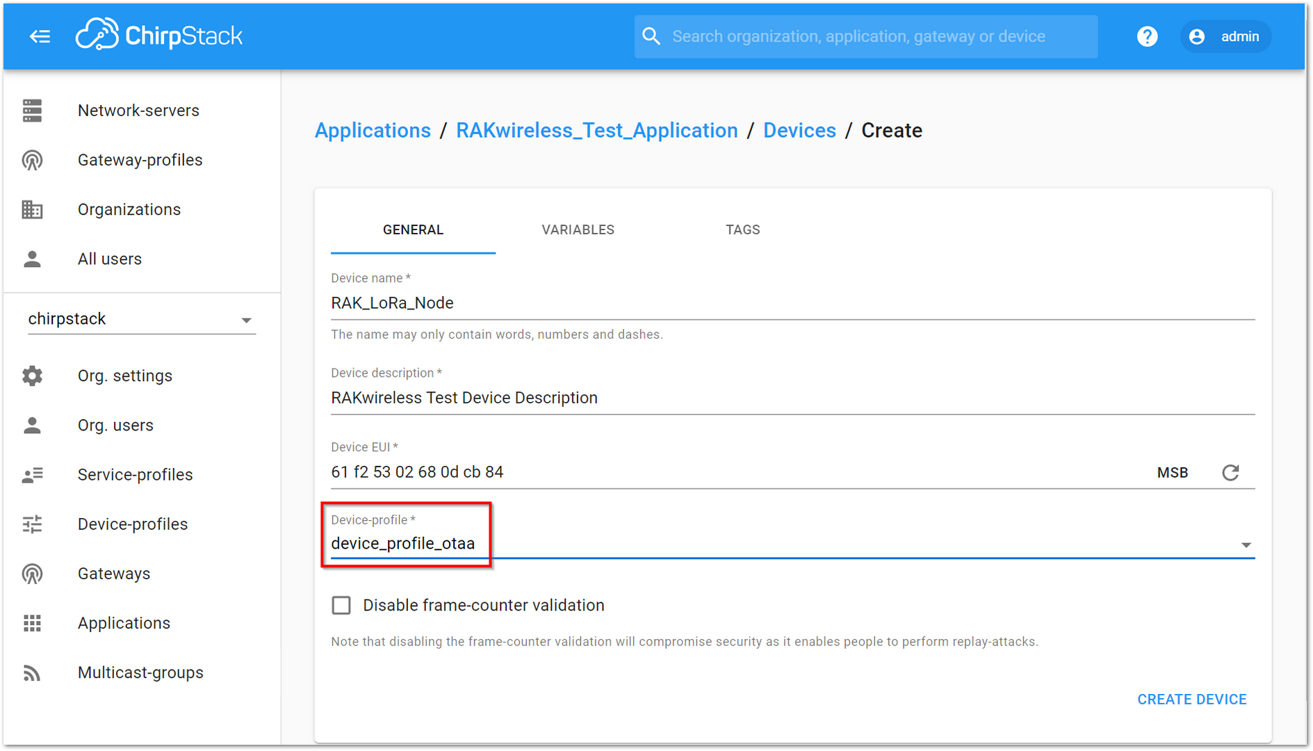 Figure 1: Select OTAA Activation Mode in ChirpStack
- Press the CREATE DEVICE button. You can either manually enter the Application Key or generate it automatically by clicking the icon highlighted in Figure 41.
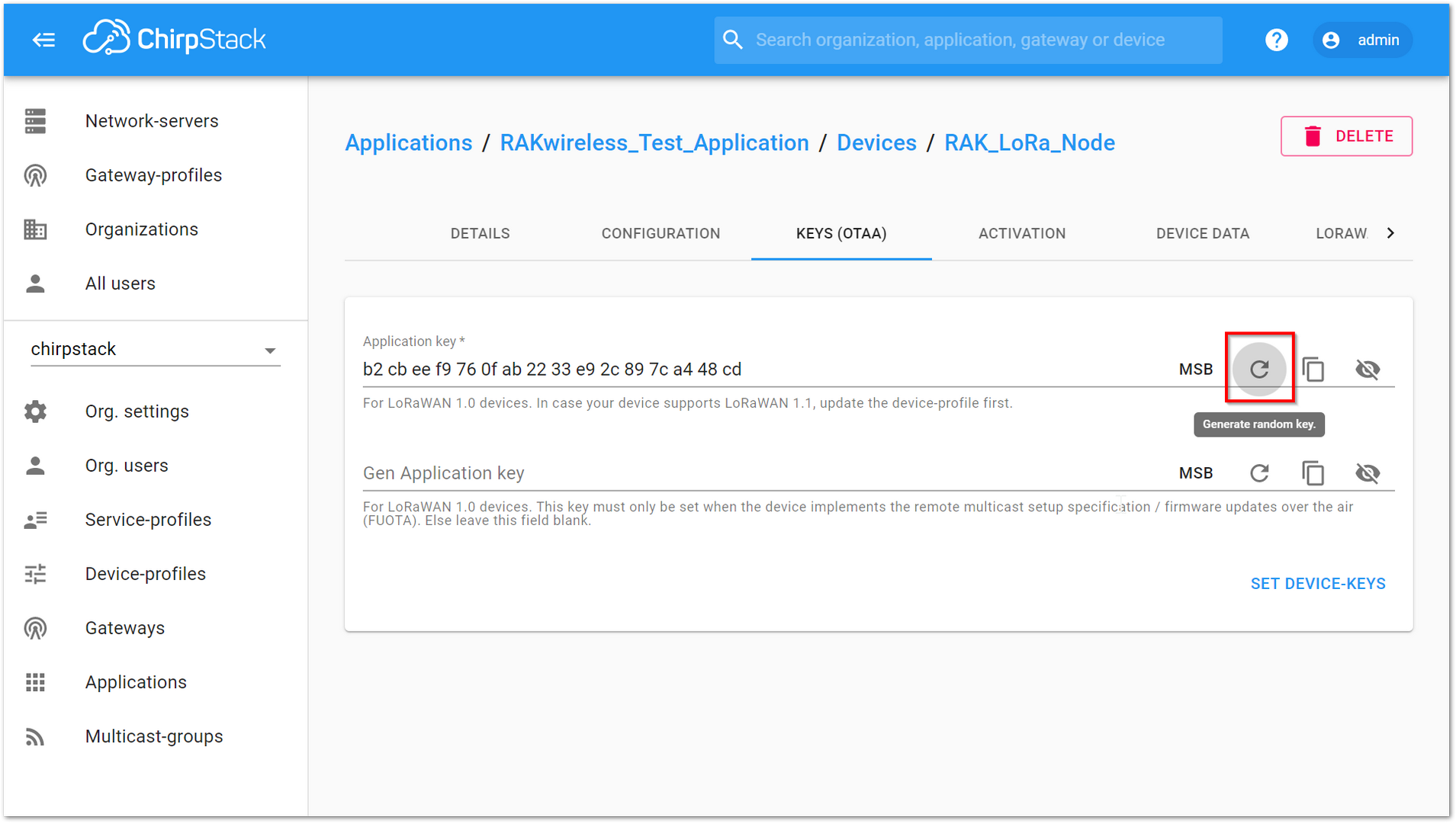 Figure 1: Application Key Generation
- Click the SET DEVICE KEYS button to finalize the configuration on ChirpStack.
- The Device EUI, which was previously set on your RAK811 Breakout Board as
dev_eui, matches the one highlighted in Figure 42.
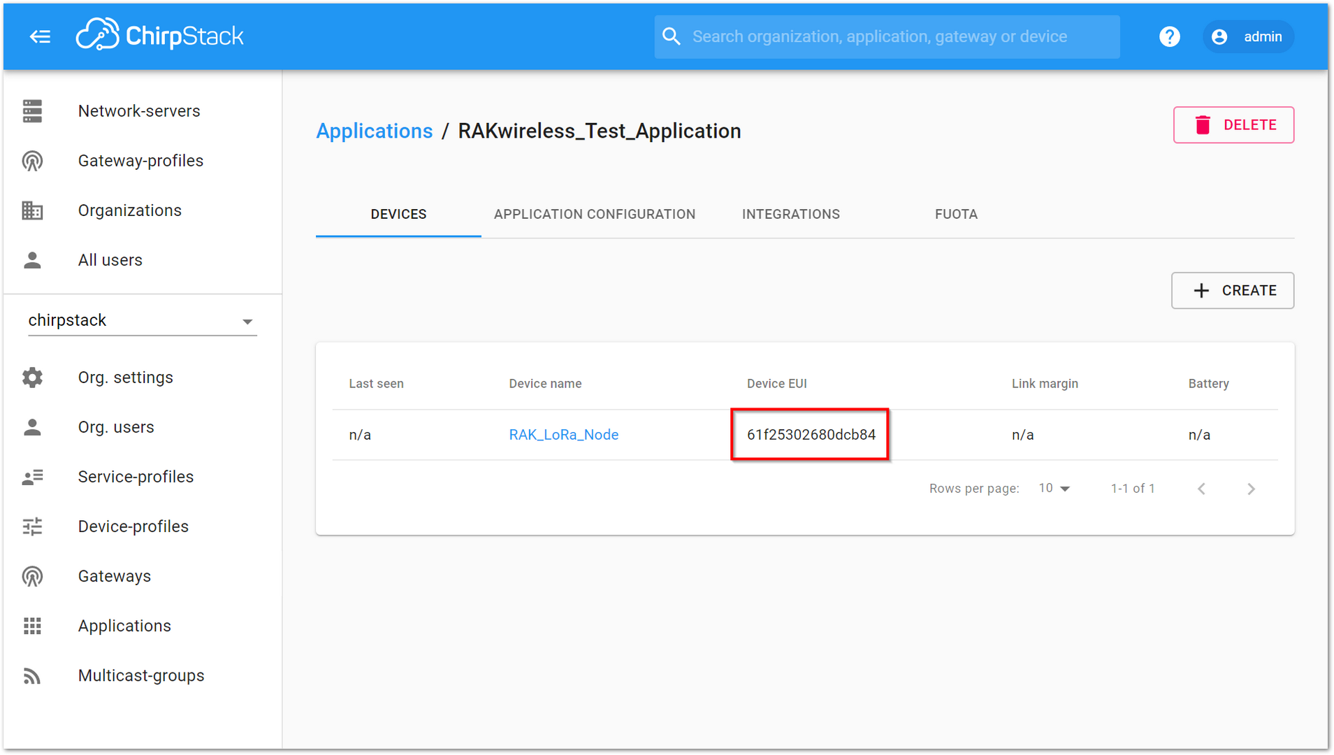 Figure 1: Device EUI Code
- The Application Key, which was previously set as
app_key, should match the one highlighted in Figure 43.
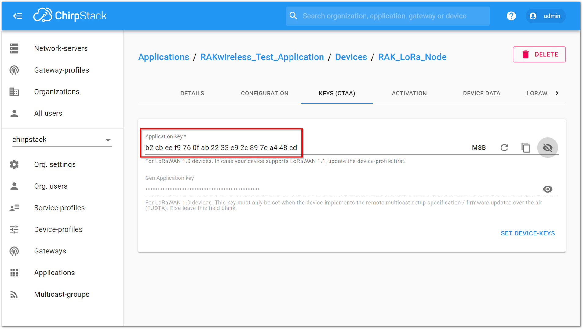 Figure 1: Application Key LoRaWAN
The Application EUI, which was set in the RAK811 Breakout Board as app_eui, is not required for ChirpStack.
- Configure the RAK811 Breakout Board using AT commands. To do this, connect your RAK811 Breakout Board to a PC, power it on, and open the RAK Serial Port Tool on your computer.
at+version
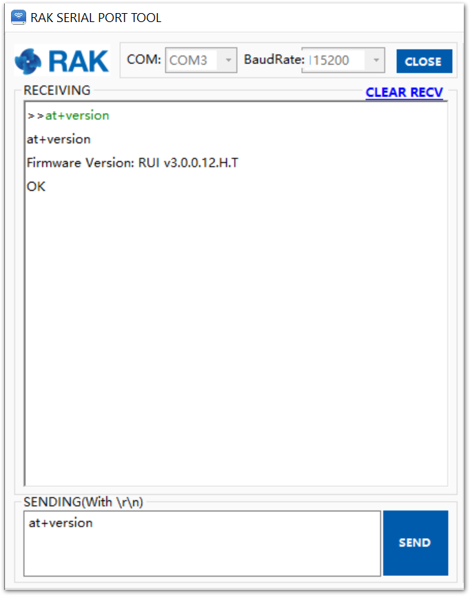 Figure 1: RAK Serial Port Tool
- If the join mode is not in OTAA, just set the LoRa join mode to OTAA and LoRa class to Class A by typing the AT commands shown in Figure 45.
at+set_config=lora:join_mode:0
at+set_config-lora:class:0
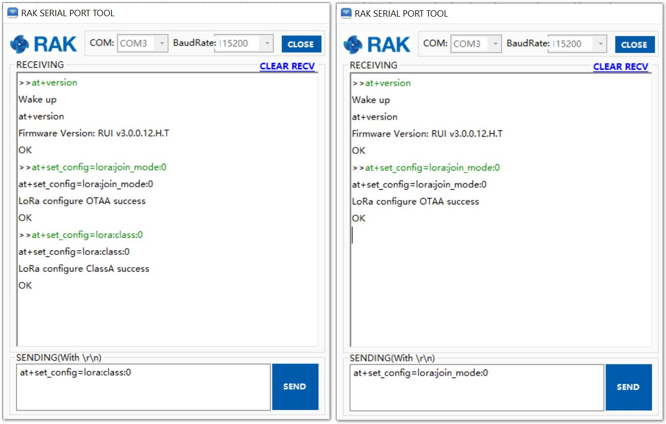 Figure 1: Set of LoRaWAN mode and class
- Type the following AT command to set the Frequency/Region, Device EUI, Application EUI, and Application Key. Remember to replace "XXX" and "XXXX" with the parameters set in the previous steps.
at+set_config=lora:region:EU868
at+set_config=lora:dev_eui:XXXX
at+set_config=lora:app_eui:XXXX
at+set_config=lora:app_key:XXXX
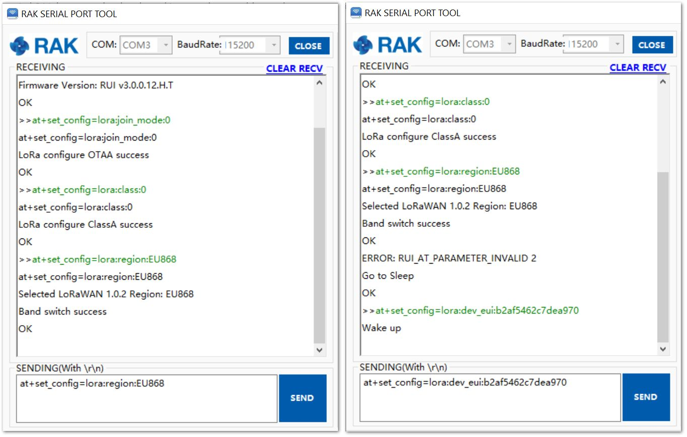 Figure 1: Setting of Frequency and Device EUI
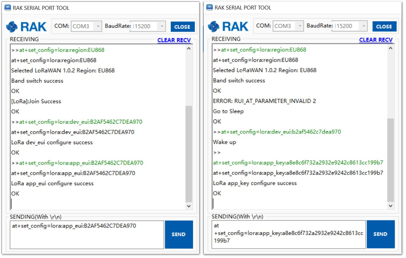 Figure 1: Setting of Application EUI and Key
- Then, join in OTAA mode.
at+join
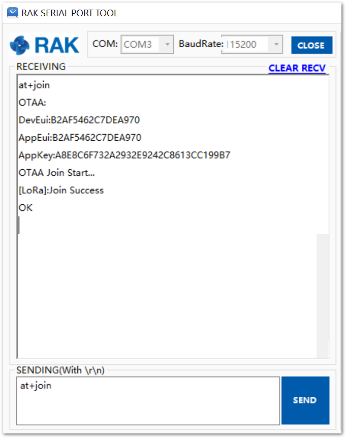 Figure 1: Join in OTAA
- Joined Successfully!
- You should view the JoinRequest and JoinAccept on the ChirpStack page.
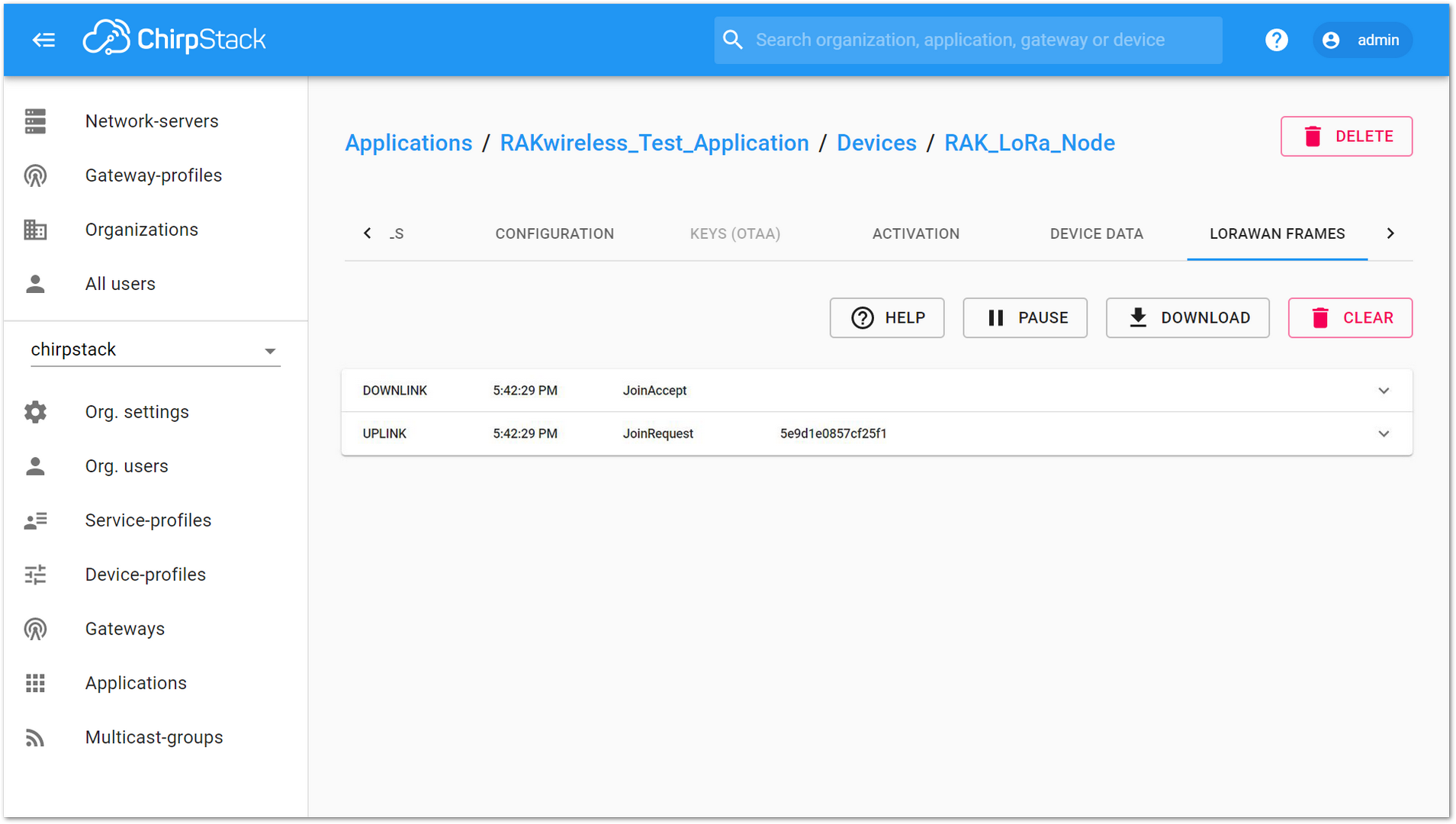 Figure 1: Join Request of the Device in the ChirpStack
- Try sending data from the RAK811 Breakout Board to the ChirpStack by typing the command below in the serial port.
at+send=lora:2:1234567890
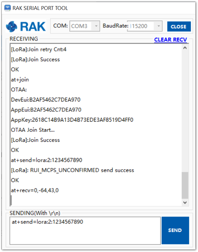 Figure 1: Send Data to ChirpStack
The message will be displayed on ChirpStack page, as shown in Figure 51.
 Figure 1: Message Received in ChirpStack
ABP Mode
- If you select DeviceProfile_ABP or DeviceProfile_ABP_CN470, it means you want to join ChirpStack in ABP mode.
Frequency AS923 in ABP Mode is not supported in Chirpstack.
 Figure 1: Chirpstack ABP Activation
- Save the parameters for ABP in the ACTIVATION item.
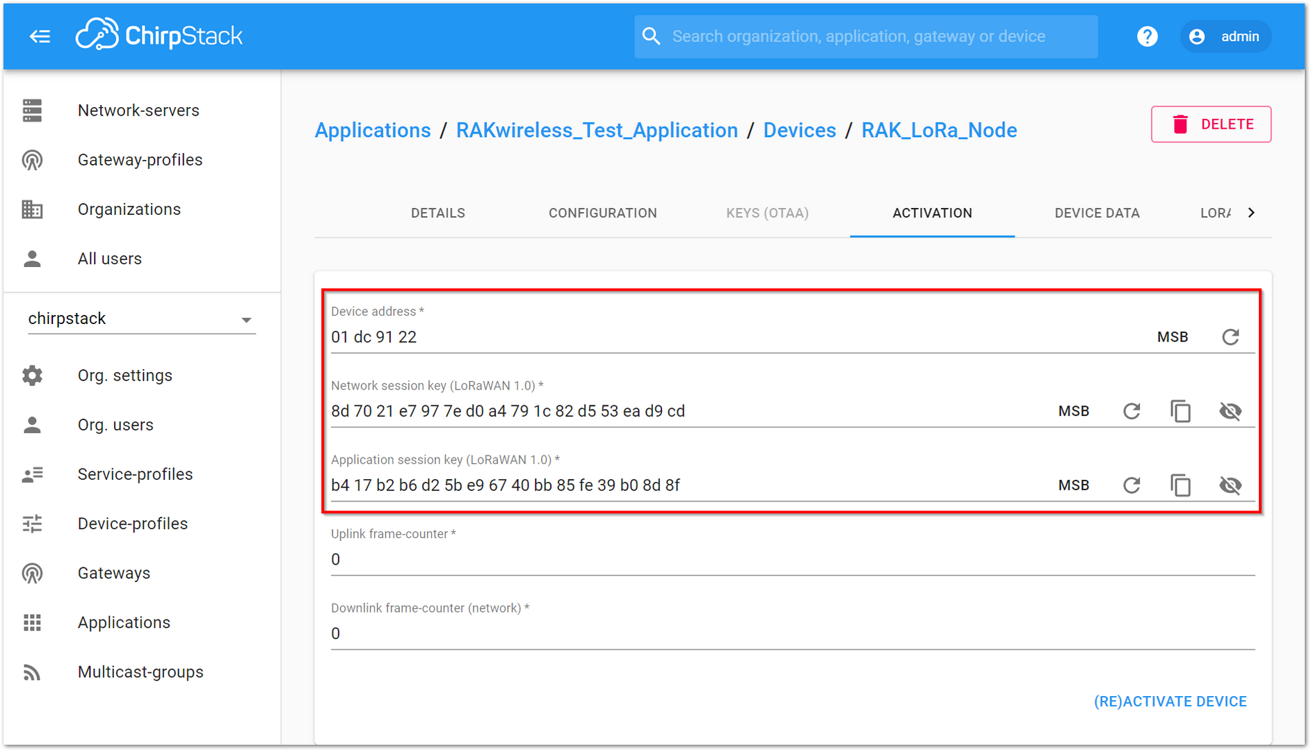 Figure 1: Chirpstack ABP Activation Parameters Needed
- Use the previously saved parameters to configure the RAK811 Breakout Board using AT commands. To set the LoRa join mode to ABP, type the following command:
at+set_config=lora:join_mode:1
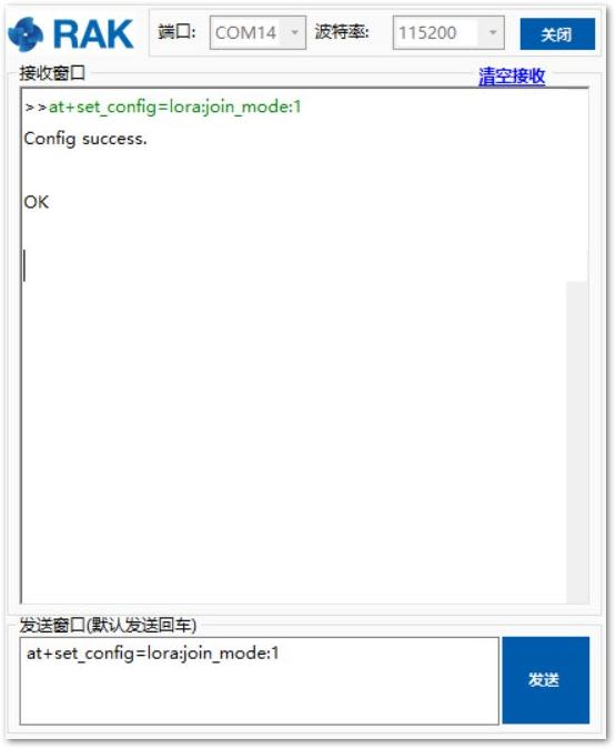 Figure 1: Chirpstack ABP Join Mode via RAK Serial Port Tool
- Set LoRa class to Class A.
at+set_config=lora:class:0
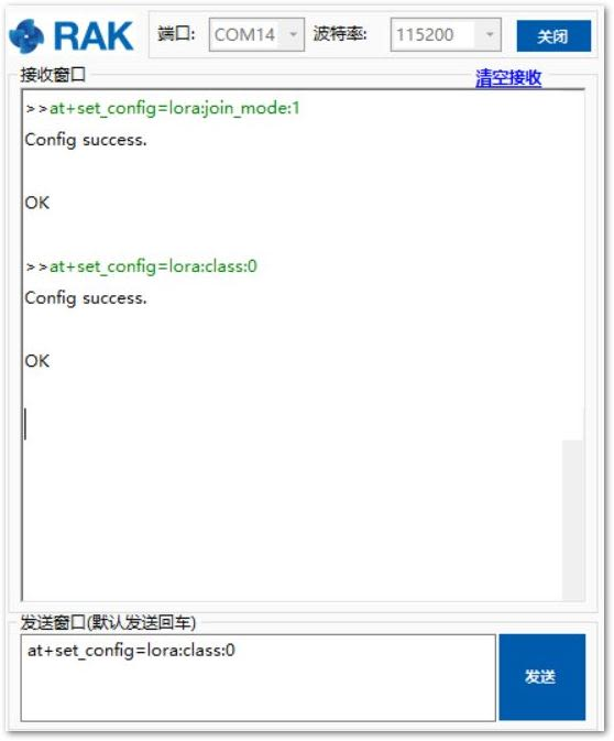 Figure 1: Chirpstack ABP Set Class via RAK Serial Port Tool
- Set the frequency/region to EU868.
at+set_config=lora:region:EU868
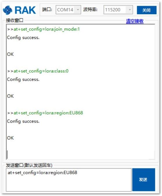 Figure 1: Chirpstack ABP Set Region/Frequency via RAK Serial Port Tool
- Set the Device Address.
at+set_config=lora:dev_addr:XXXX
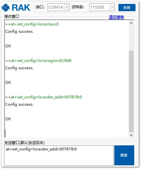 Figure 1: Chirpstack ABP Set Device Address via RAK Serial Port Tool
- Set the Network Session Key.
at+set_config=lora:nwks_key:XXXX
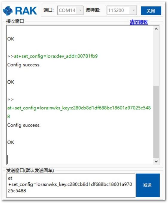 Figure 1: Chirpstack ABP Set Network Session Key via RAK Serial Port Tool
- Set the Application Session Key.
at+set_config=lora:apps_key:XXXX
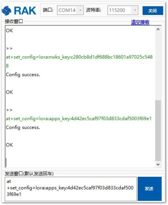 Figure 1: Chirpstack ABP Set Application Session Key via RAK Serial Port Tool
After configuring all the parameters, reset your RAK811 Breakout Board to save the parameters.
- Join in ABP mode.
at+join
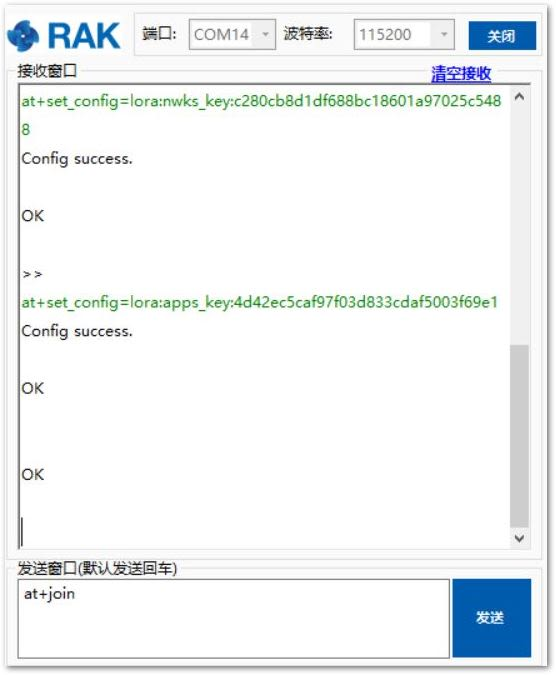 Figure 1: Chirpstack ABP Join via RAK Serial Port Tool
Although joining is not required in ABP mode, you still need to set this AT command to validate the parameters configured for ABP mode.
- Try to send a data from RAK811 Breakout Board to ChirpStack.
at+send=lora:2:1234567890
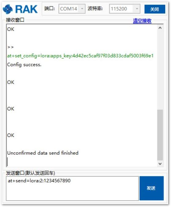 Figure 1: Chirpstack Sample Data Sent via RAK Serial Port Tool
- You will see the data, which is just sent from RAK811 Breakout Board on ChirpStack page:
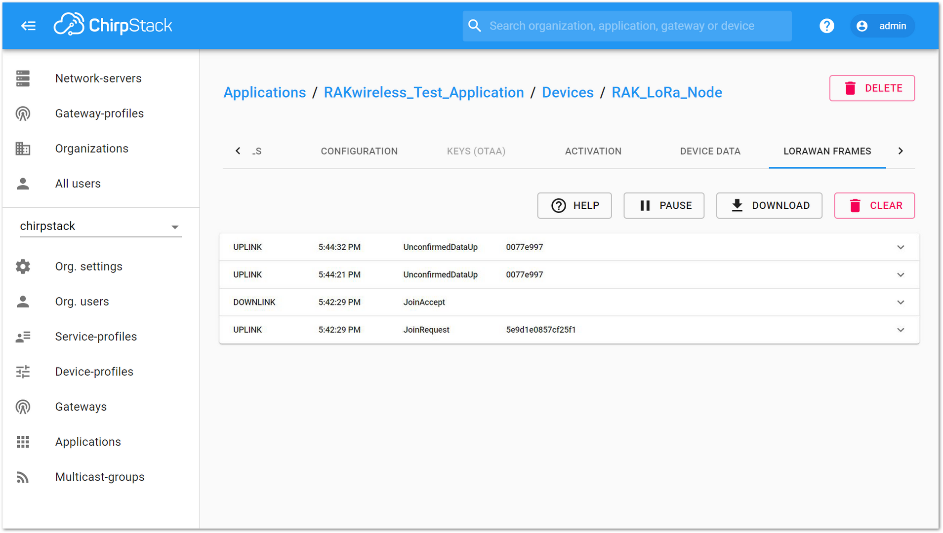 Figure 1: Chirpstack Data Received Preview
LoRa P2P Mode
This section shows how to use LoRa P2P mode. You will be using EU868 as the frequency, although it is applicable to other standard bands.
-
First, find two RAK811 Breakout Board which can work on EU868 frequency and make sure their firmware version isn’t less than V3.0.0.1.
-
Next, connect these two RAK811 Breakout Board with PC through UART, and open two serial port tool on PC.
-
Set the RAK811 to work in LoRa P2P mode. Open the RAK Serial Port Tool and send the following command:
at+set_config=lora:work_mode:1
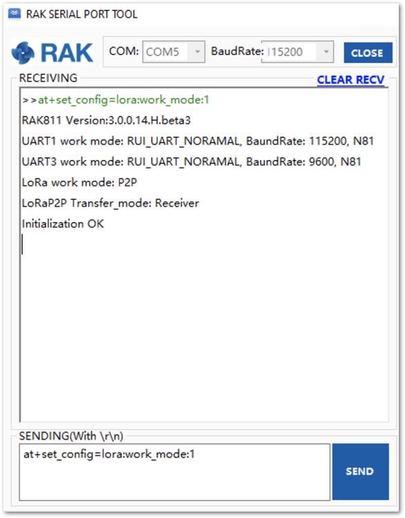 Figure 1: P2P Initialization
- Configure LoRa P2P parameters for both of them.
at+set_config=lorap2p:XXX:Y:Z:A:B:C
For this example, the LoRa parameters are the following:
- Link frequency: 869525000 Hz
- Spreading factor: 7
- Bandwidth: 125 kHz
- Coding Rate: 4/5
- Preamble Length: 5
- Power: 5 dBm
Refer to the Configuring Using AT Commands section to learn more about the definition of the parameters used.
Hence, it is translated into the following RAK811 AT command and sent to both units.
at+set_config=lorap2p:869525000:7:0:1:5:5
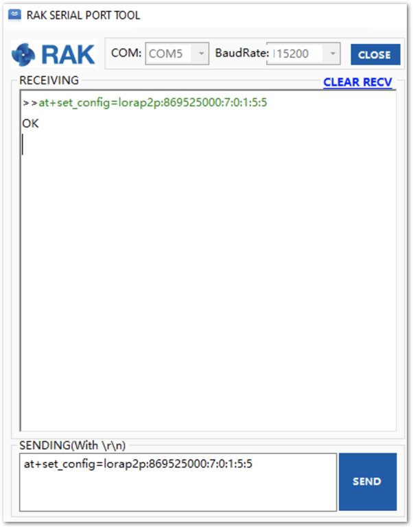 Figure 1: Configure P2P in both RAK811 Breakout Board Nodes
- Set the transmission mode of the module. Unit 1 is configured as the sender, and Unit 2 is set to the receiver by AT command.
at+set_config=lorap2p:transfer_mode:2

at+set_config=lorap2p:transfer_mode:1
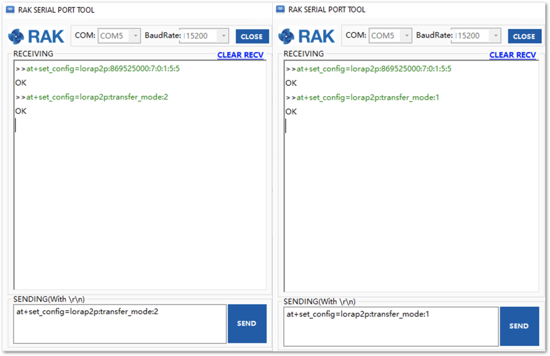 Figure 1: Set Modes in both RAK811 Module
- Try sending a message from Unit 1 to Unit 2.
at+send=lorap2p:1234567890
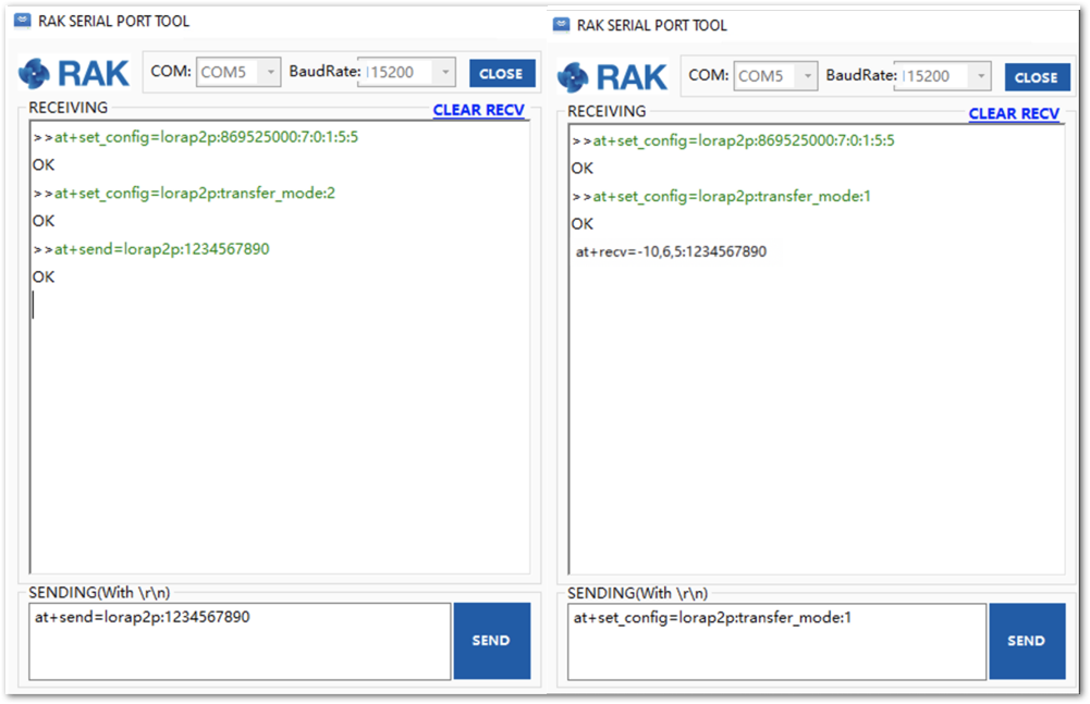 Figure 1: Message sent and received status in the two modules
You have successfully finished your RAK811 Breakout Board set up.
Miscellaneous
Upgrading the Firmware
For RAK811 modules with firmware version V3.0.0.12 and below, you need to use the STM32CubeProgrammer to upgrade the firmware and upload the .hex file (not the .bin file) of the latest RAK811 firmware. Firmware versions below V3.0.0.12 have a different bootloader code and are incompatible with the RAK DFU Tool.
Follow the steps below to upgrade the firmware in Device Firmware Upgrade (DFU) mode via the UART1 interface:
-
Download the latest application firmware of the RAK811 that can be found on the datasheet.
-
Download and open the RAK Device Firmware Upgrade (DFU) tool.
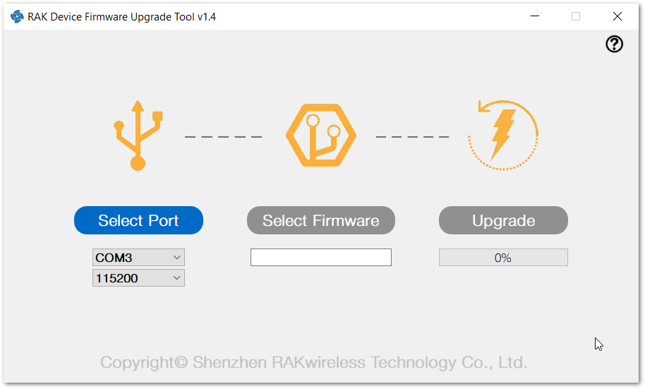 Figure 1: RAK Upgrade Tool
- Click Choose File and choose the firmware you have downloaded for your desired frequency band.
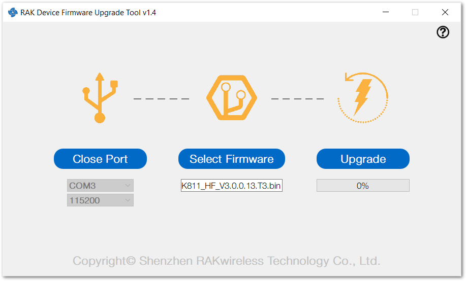 Figure 1: Choose the Correct Upgrade file
- Click Start to upgrade. This may take a minute.
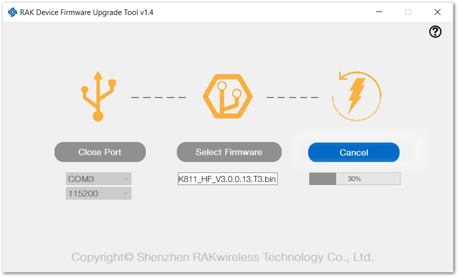 Figure 1: Firmware Upgrading in Process
- You should see the same pop-up window, as shown in Figure 62, if everything was successful.
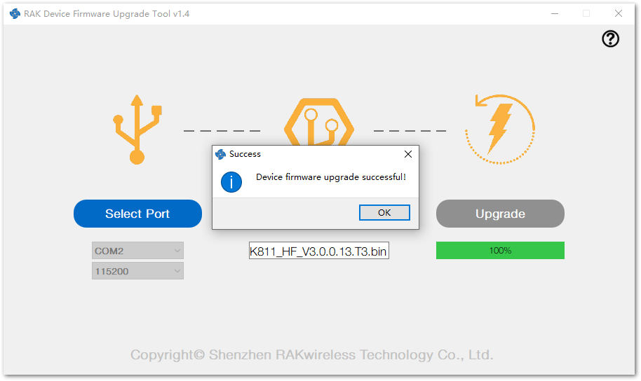 Figure 1: Successfully Upgraded Firmware
- Close the upgrade tool and OPEN the serial port tool again.
- It is recommended to use the RAK Serial Port Tool as it includes ready-to-use AT commands that are very helpful. You can download it for free from the RAK website at this RAK directory.
- Choose the correct COM port and set the baud rate to 115200. Then, open the serial port and enter the AT command shown below to restart. Another option is to press the RST button on the RAK811 Breakout Board.
at+set_config=device:restart
If you want to configure your RAK811 Breakout Board using the available AT commands, check the AT Commands for RAK811 Breakout Board.