RAK7240V2/RAK7240CV2 Unboxing & Installation
Before physically mounting the gateway outdoors, it is recommended to complete the network and LoRaWAN configuration steps described in the Quick Start Guide.
This ensures that once the gateway is powered on at the installation site, it can immediately join the network without requiring on-site configuration or physical access.
Prerequisites
Package Inclusions
Variant with DC input interface
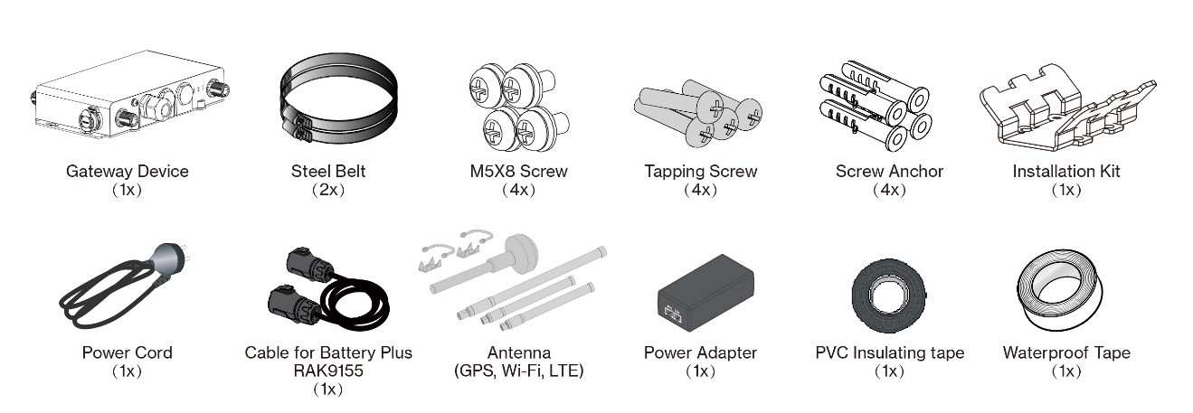 Figure 1: RAK7240V2/RAK7240CV2 package list 1
Variant without DC Input interface
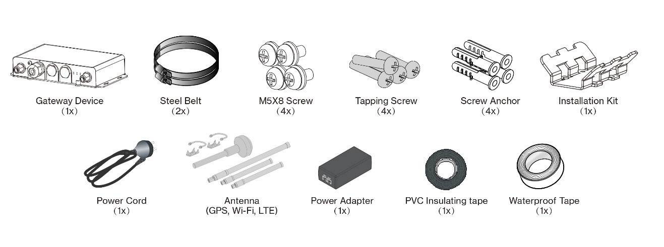 Figure 1: RAK7240V2/RAK7240CV2 package list 2
-
LoRa® antenna is not included and must be purchased separately.
-
LTE antennas are included only with 8-channel cellular models (RAK7240CV2).
Additional Hardware Required
-
Ethernet Cable (RJ-45 Port) – Required for network setup
-
A Windows/MacOS/Linux Computer – For configuration via Web UI
-
LoRa® Antenna(s) – One or two antennas may be required, depending on your gateway model
-
NanoSIM Card (for LTE version) – Size: 12 x 9 x 0.67 mm
Installation
Insert SIM Card (For cellular models only — RAK7240CV2)
The SIM card slot of the cellular versions is not hot-swappable. Make sure the gateway is switched off before inserting or ejecting the SIM card.
- Start by unscrewing the cap of the NanoSIM interface on the gateway enclosure to expose the SIM card slot.
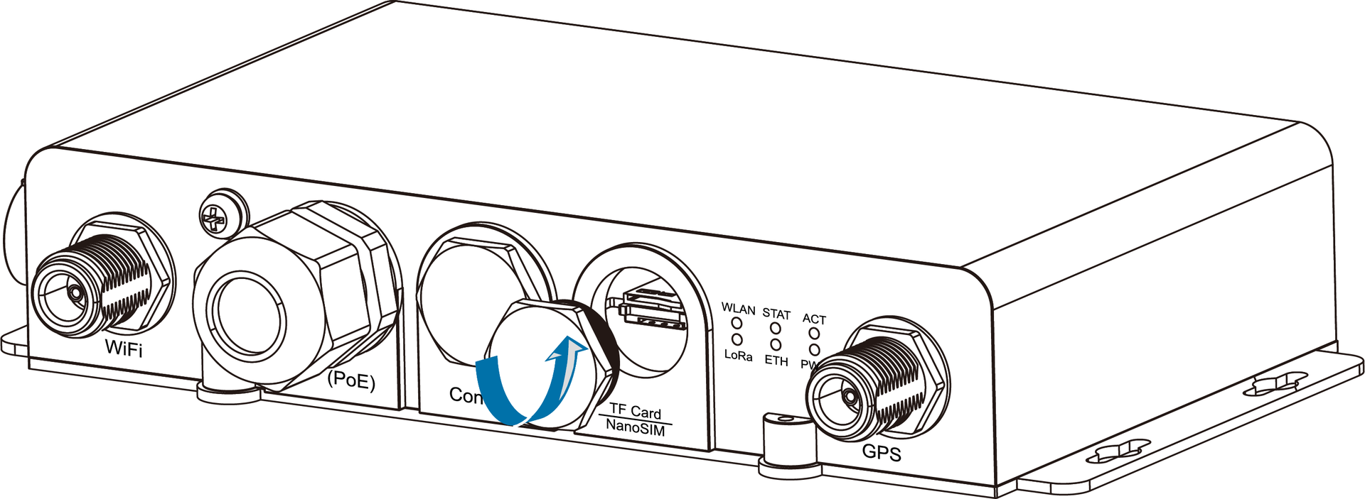 Figure 1: Unscrewing the cap of the NanoSIM interface
- Insert the NanoSIM card into the lower slot labeled “NanoSIM,” with the metal contacts facing up.
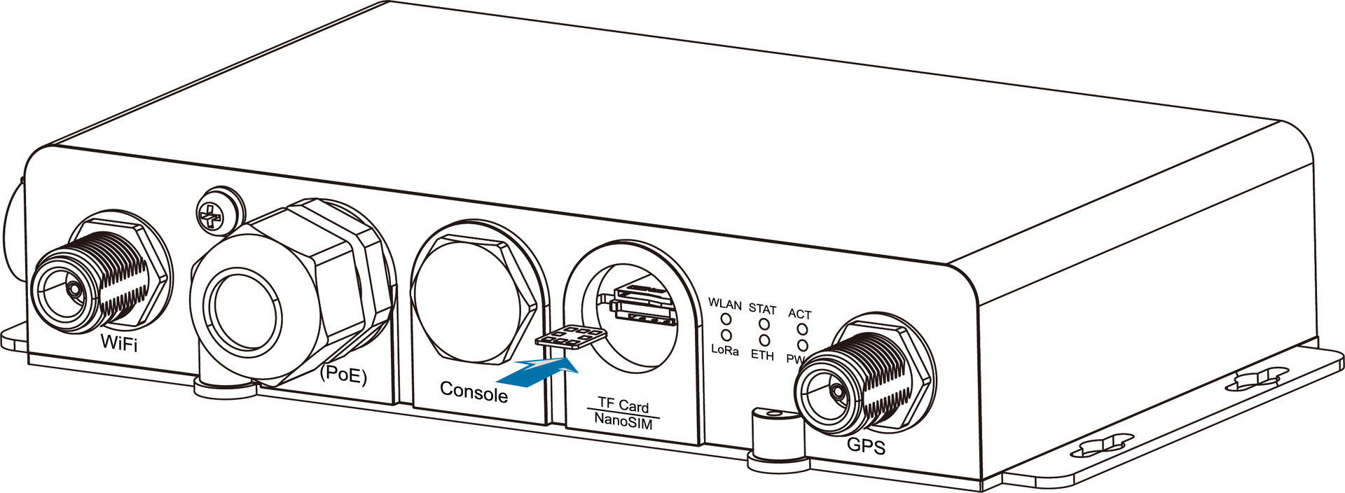 Figure 1: Inserting the SIM card
- Once completed, screw back the metal cap. Make sure it is tightly screwed.
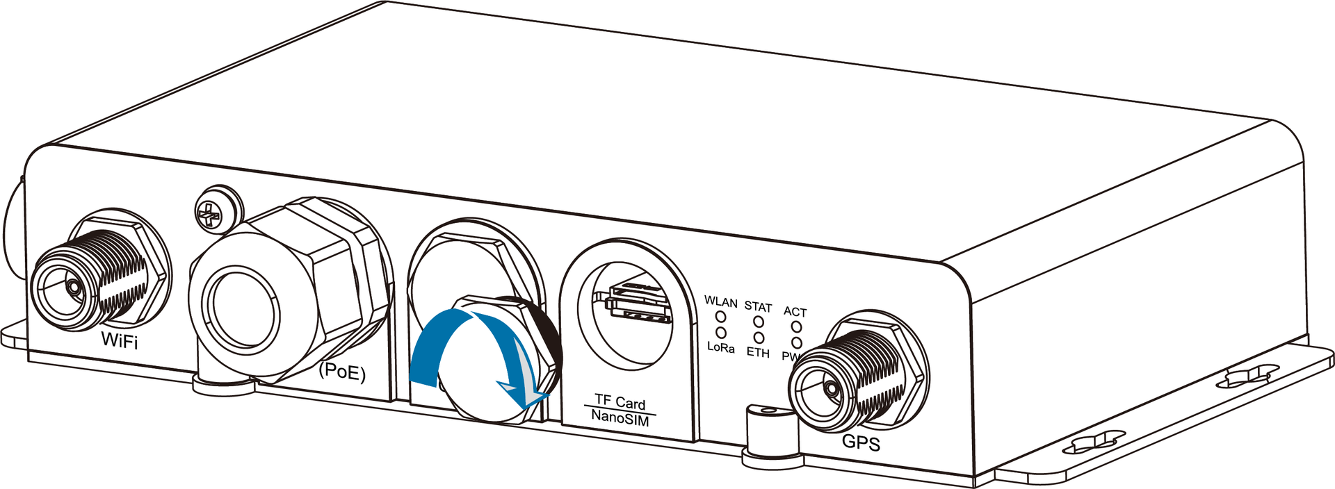 Figure 1: Screwing back the metal cap
Mount the Gateway
- Fix the installation kit at the bottom of the device with four M5 x 8 mm screws.
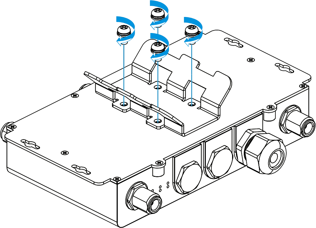 Figure 1: Fixing the installation kit to the RAK7240V2/RAK7240CV2
- Slide the steel band clamps through the rectangular hole of the installation kit. Wrap the band clamps around the pole, lock them, and then tighten the clamps using a screwdriver.
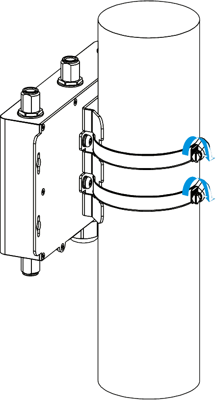 Figure 1: Fixing the RAK7240V2/RAK7240CV2 to a Pole
Install Antennas and Cables
Lightning Protection
Lightning strikes can generate powerful electrical surges that may harm sensitive electronic devices. It is essential to take appropriate precautions to minimize the risk of damage. The warranty provided does not cover damages resulting from lightning strikes or other acts of nature.
To ensure optimal performance and protect your equipment from potential damage, it is strongly recommended to install proper grounding and lightning protection for:
-
All antenna connectors (LoRa®, GPS, Wi-Fi, LTE)
-
The ETH(PoE) port
-
The gateway enclosure
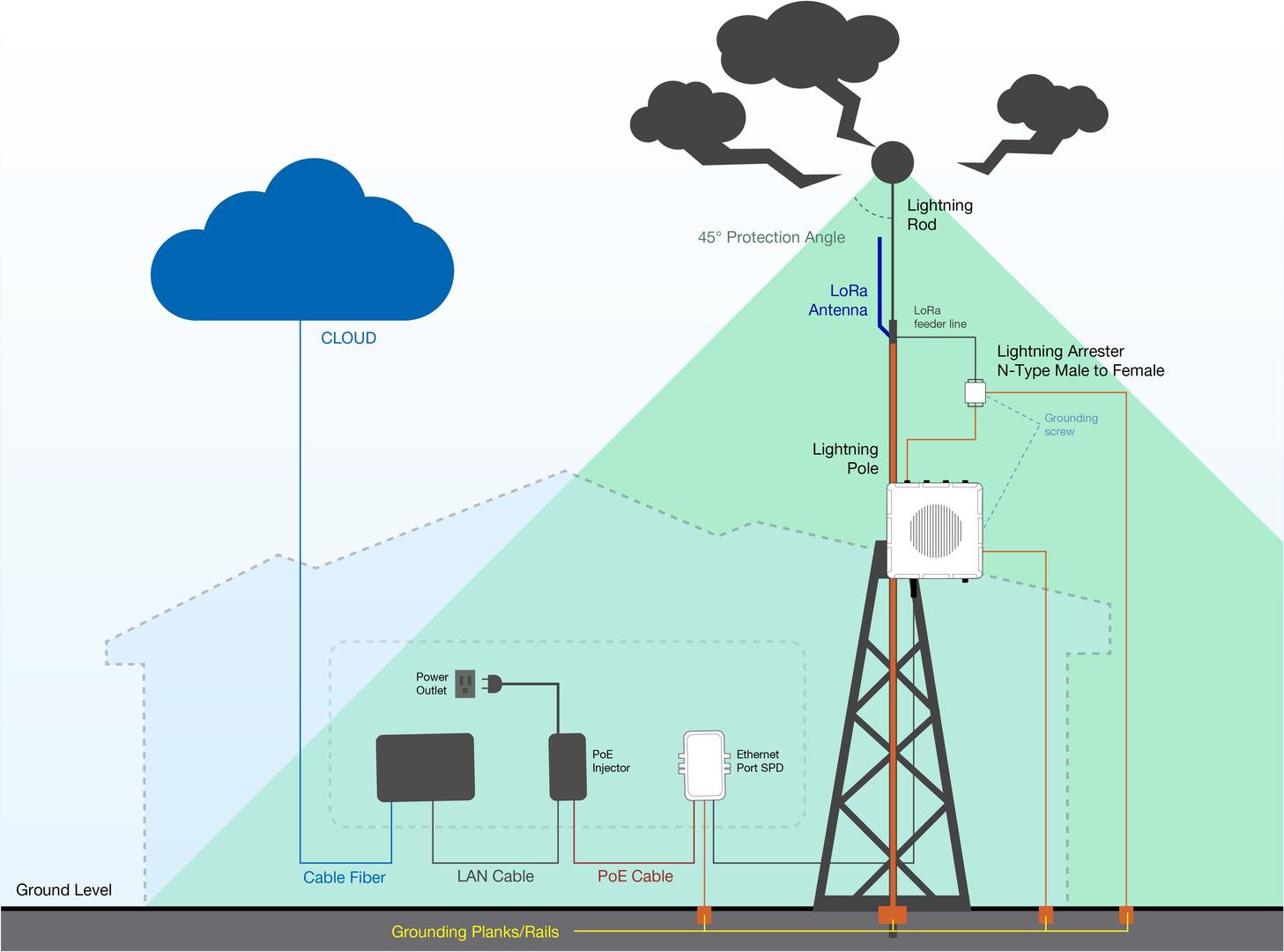 Figure 1: Full lightning protection set-up
Outdoor Surge Protection System
- Antenna Grounding Install a lightning arrestor on each antenna’s N-type terminal (LoRa®, LTE, Wi-Fi, GPS). The arrestors must be N-type Female to Male to match the antenna and enclosure connectors. Use 10 AWG or thicker grounding wire to connect the arrestor's screw terminal to the grounding rail mounted on the building wall or a grounding bar in field deployments.
- Gateway Grounding Connect the grounding screw located on the bottom side of the gateway to the same grounding rail or bar using a 10 AWG or thicker wire. This ensures proper discharge path for any electrical surges through the gateway chassis.
Indoor Surge Protection
To protect indoor devices connected to the gateway (e.g., PoE injectors, switches, routers), install an Ethernet SPD (Surge Protection Device) along the cable between the gateway and the PoE injector. Make sure you connect its grounding wire terminal to an appropriate building grounding point.
Recommended Equipment
- Lightning Arrestor for GPS Antenna: A surge protection device designed specifically for GPS antennas. It uses a high-pass filter to block low-frequency lightning-induced interference while maintaining minimal insertion loss for GPS signals. The device integrates a TVS diode and gas discharge tube (GDT) to protect the DC feed circuit from transients and over-voltage events.
- Lightning arrestor for the LoRa, LTE and Wi-Fi antennas: This is a surge protection device for securing transceivers against over-voltage and surge current induced by lightning bolts. RAKwireless recommends installing lightning arrestors on all N-type antenna terminals, including LTE and 2.4G Wi-Fi antennas.
- Signal Surge Protective Device: Designed for CAT6 or Class E network cables, this SPD protects Ethernet-connected equipment from voltage surges induced by lightning or internal switching transients. It is widely used in industrial and office communication systems, including Gigabit Ethernet, ATM, ISDN, and VoIP.
Connect Antennas and Cables
After completing lightning protection installation (if applied):
-
Connect the LoRa®, Wi-Fi, and GPS antennas to their respective ports. If lightning arrestors have been installed, connect the antennas through the arrestors.
-
For cellular versions, connect the LTE antennas in the same way.
-
(Optional) If using PoE for power or Ethernet for data, connect an Ethernet cable to the ETH (PoE) port.
Weather Protection
To better protect the Ethernet cable gland and all antenna connectors from from moisture and environmental damage, you need to cover them with PVC tape.
- Clean the surface area of the connector that will be wrapped. Wrap a layer of PVC tape with a 50% overlap according to the rotation direction of the connector. Continue wrapping the PVC tape to about 10 mm below the end of the connector.
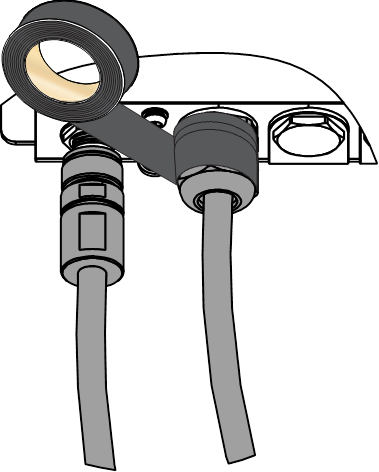 Figure 1: Wrapping with PVC tape
- Cut off about 50 cm waterproof tape. Stretch it to double its length and wrap three layers around the connector with a 50% overlap. Hold the tape in place with your hand for a few seconds.
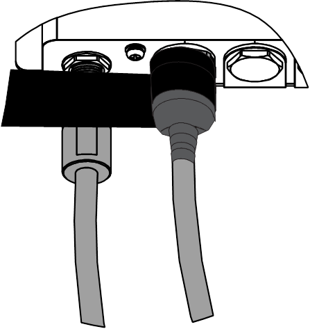 Figure 1: Wrapping with waterproof tape
- Wrap three additional layers with PVC tape with natural uncoiling force and a 50% overlap. Ensure to cover the head and the tail of the connector.
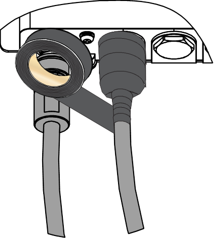 Figure 1: Final PVC wrapping
Power On the Gateway
Do not power the device if any antenna port has been left open. In case you do not desire to use one or more antenna features, make sure to terminate the port with a 50 Ohm load.
Your gateway supports multiple power input options depending on the model variant:
PoE (Power over Ethernet)
-
Connect the Ethernet cable—already attached to the gateway’s ETH (PoE) port—to the PoE port of the injector.
-
Plug the injector into a power outlet to power up the gateway.
 Figure 1: Powering the gateway using PoE
DC Power Input (9–24 V DC)
The gateway includes a pre-terminated DC power cable, designed for direct connection with RAK Battery Plus.
To use RAK Battery Plus, simply connect the included DC power cable between the battery and the gateway’s DC input port.
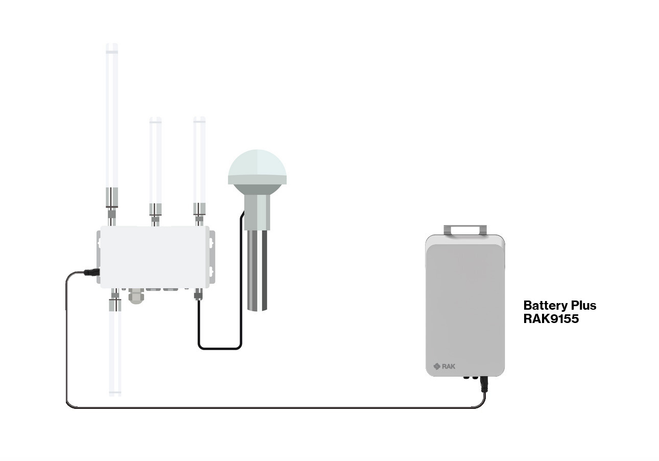 Figure 1: Powering the gateway using RAK Battery Plus
RAK9155 Battery Plus is not included in the bundle, it needs to be purchased separately.
If you’re using your own 9–24 V DC power supply, you may trim the open end of the cable and connect the wires to your power source.
Polarity:
Red wire = Positive (+)
Black wire = Negative (–)
Use caution when trimming and wiring. Incorrect polarity may damage the gateway and void the warranty.