RAK7249 Quick Start Guide
Prerequisites
What Do You Need?
- RAK7249 WisGate Edge Max
- A Windows/Mac OS/Linux Computer
The SIM card slot of the cellular versions is not hot-swappable. Make sure the gateway is switched off before inserting or ejecting the SIM card.
What's Included in the Package?
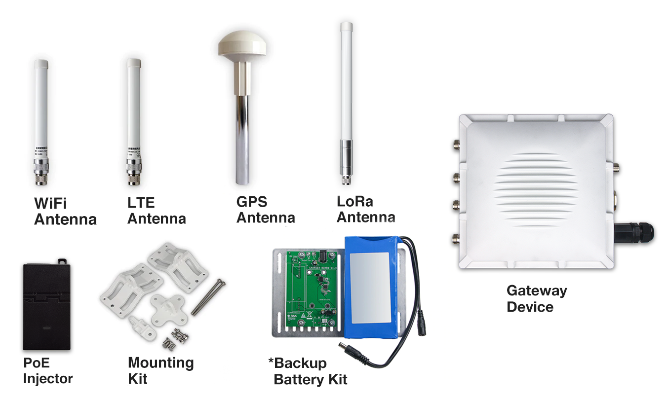 Figure 1: RAK7249 Package Contents
- The included type and number of antennas and the Backup Battery Kit is optional, depending on the purchased bundle.
Product Configuration
gateway-installation-guide
For details about the interfaces and connectors of RAK7249 WisGate Edge Max Gateway enclosure, refer to the Datasheet.
Assembly
- Fix the support plate on the base with three M3*6 screws.
 Figure 1: Fixing the support plate
- Install the motherboard with four M3*6 screws.
 Figure 1: Installing the motherboard
- Install the LoRa card. The motherboard supports two LoRa cards. Slot one supports only SPI type, and slot two supports only USB type.
 Figure 1: Installing the LoRa card
-
If your board supports the cellular function, you can install your SIM card into the motherboard’s SIM card slot.
-
Installation of RF cables, Ethernet cable, and reserved hole plugs.
 Figure 1: Installing the cables and plugs
- Connect the cables to the motherboard. The connectors on the motherboard are shown in Figure 6.
 Figure 1: Connecting the cables to the motherboard
You must use the Wi-Fi MAIN connector to connect the Wi-Fi antenna.
-
If you have a Backup Battery Kit, connect with the backup battery to the motherboard.
-
Fix the M3 hexagon spacers on the plate with four screws, and then fix the battery charging PCB board on top of them.
 Figure 1: Fixing the battery charging PCB board
- Fix the battery with cable ties beside the charging PCB board. If the cable tie is not long enough, two ties can be connected.
 Figure 1: Fixing the battery
- Fix the four M3*30mm hexagon spacers on the bottom plate.
 Figure 1: Adding Spacers
- Connect the cables as shown in Figure 10.
- Connect the PH2.0 socket on the motherboard and the charging PCB board with the 2pin signal cable.
- Connect the DC socket of the charging PCB board and the battery socket with a DC Plug cable.
- Plug the output plug of the battery into the DC socket of the motherboard.
 Figure 1: Connecting the cables
- Fix the Charge Module in the enclosure and tighten with four screws.
 Figure 1: Fixing the Charge Module
- Close the top cover with M4*12 screws. Make sure that the rubber seal is placed correctly in the groove between the box and the lid to prevent leaks.
 Figure 1: Closing the enclosure
Installation
Instructions on mounting and securing the mounting kit to the enclosure and the bearing pole.
- Fix the included cross bracket on the bottom of the enclosure with four M6*12 bolts.
 Figure 1: Mounting the cross bracket
- Place two pieces of the clamp around the pole and tighten them with the included M6*110 bolts, washers, and nuts.
 Figure 1: Mounting the clamp to the pole
- Connect the pole clamp and the cross bracket by securing the last piece of the mounting kit in place using M6*30 bolts, washers, and nuts.
 Figure 1: Fixing the enclosure to the pole clamp
Weather Protection
To better protect the Ethernet cable gland and the antenna connector from the weather, you need to cover them with PVC tape.
- Clean the surface area of the connector that will be wrapped. Wrap a layer of PVC tape with a 50% overlap according to the rotation direction of the connector. Continue wrapping the PVC tape to about 10 mm below the end of the connector.
 Figure 1: Wrapping with PVC tape
- Cut off about 50 cm waterproof tape. Stretch it to double the length. Wrap three layers around the connector with a 50% overlap. Hold the tape in place with your hand for a few seconds.
 Figure 1: Wrapping with waterproof tape
- Wrap three additional layers with PVC tape with natural uncoiling force and a 50% overlap. Make sure to cover the head and the tail of the connector.
 Figure 1: Final PVC wrapping
solar-panel-and-battery-kit-installation
This document shows the step-by-step guide on how to set-up the Solar Panel and Battery Kit used for the RAK7249 - Macro Outdoor Gateway. Such steps must be thoroughly read and understood to avoid damaging the device.
Package List
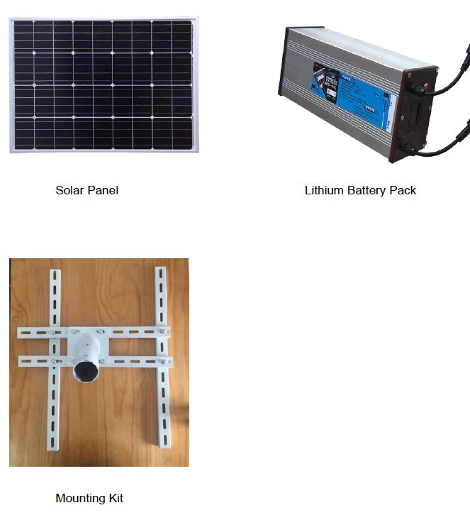 Figure 1: solar-panel-and-battery-kit-installation Package List
Specifications
Solar Panel
1. Dimensions
The dimension of the Solar Panel included in the kit is 665 x 815 millimeter. Provided in the image below are the detailed dimensions of the solar panel for extended functions.
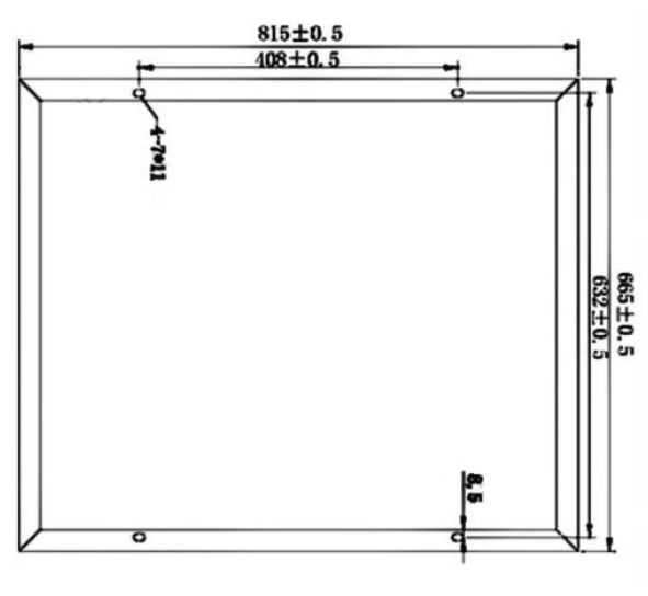 Figure 1: Solar Panel Dimensions
2. Electrical Characteristics
The table below is the electric characteristics of the Solar Panel included in the kit. It is best advised to have your electric parameters within the set values to maximize its functions and to avoid damage that could furtherly affect your RAK7249 - Macro Outdoor Gateway's performance.
| Maximum Power (Pmax) | 80 Watts |
|---|---|
| Voltage at Pmax (Vmp) | 18 Volts |
| Current at Pmax (Imp) | 2.2 - 5.5 Amperes |
| Open Circuit Voltage (Voc) | 21.6 Volts |
| Short Circuit Current (Isc) | 2.3-6.5 Amperes |
Lithium Battery
1. Dimensions
The dimensions of the Lithium Battery included in the kit is 140 x 90 x 350 millimeter.
2. Operational Temperature
The operational temperature of the Lithium Battery is -20˚C ~ 60˚C. It is advised to have your ambient temperature be within this temperature range to avoid failures or damage to the battery.
3. Electrical Characteristics
| Nominal Output Voltage | 12.6 Volts |
|---|---|
| Nominal Output Current | 2 Amperes |
| Capacity | 50 Ah (Ampere-hour) |
| Charge Voltage | 18 Volts |
Installation Guide
- Install the bolts in the holes which are circled in red in the following image below. This will make an "H-shaped" base, for the Solar Panel to be mountable on the top. The circular pipe in the middle of the shape is meant to fit over a circular shaped pole, so the whole construction sits on top with the panel facing upwards on an angle.
Tighten the nuts and make sure that the rails that make up the base are holding tight against each other.
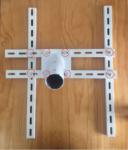 Figure 1: H-Shaped Nuts and Bolts Placement for the Bracket
- Mount the battery on top of the two parallel rails in the middle. Make sure it is as close as possible to the middle of the construction. Fasten it to the rails with four bolts, each having a washer and a nut. Refer to the image below on how to insert the bolts into the railing that is part of the bottom of the battery casing.
Tighten the bolts as possible as the battery is quite heavy.
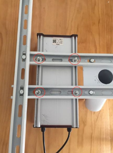 Figure 1: Mounting the Battery to the Bracket
- Connect the input port power cable of the Lithium Battery to the screw terminals on the back of the Solar Panel. The image below shows the connection on the back of the solar panel.
Make sure to follow the connection in the image below as interchanging the wires would reverse the polarity. Reversing the polarity when connecting the battery is dangerous and may cause a fire.
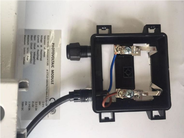 Figure 1: Lithium Battery Input Cord to Solar Panel Connection
- The following image then shows where the cable connection between the solar panel entering the input terminal on the battery is performed in Step 3.
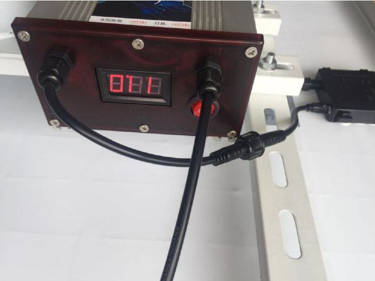 Figure 1: Lithium Battery to Solar Panel Outside Connection
- Connect the Lithium Battery output terminal cable to the input power cable of the RAK7249 - Macro Outdoor Gateway as shown in the following figure.
 Figure 1: Lithium Battery Output Cord to RAK7249 - Marco Outdoor Gateway Connection
Your battery life will vary depending on local illumination intensity. For a 50Ah battery and an 80W solar panel, such as the ones used in the kit, the RAK7249 - Macro Outdoor Gateway should function for about 4 days. This is the worst case scenario where there is constant heavy rain and or constant presence of clouds.
If you live in an extreme condition environment that results in operational time significantly less than 4 days, reconsider increasing the battery capacity and installing a solar panel with greater power output to compensate such issues.
- Mount the whole installation you have assembled on top of a circular pole. Put the panel facing up and insert the pole in the pipe opening on the bottom of the construction. Make sure the pole is of a sufficiently small diameter to fit with a recommended value of 65 millimeters. Use 6 pieces of M8-bolts to fix the bottom to the construction as shown in the image below.
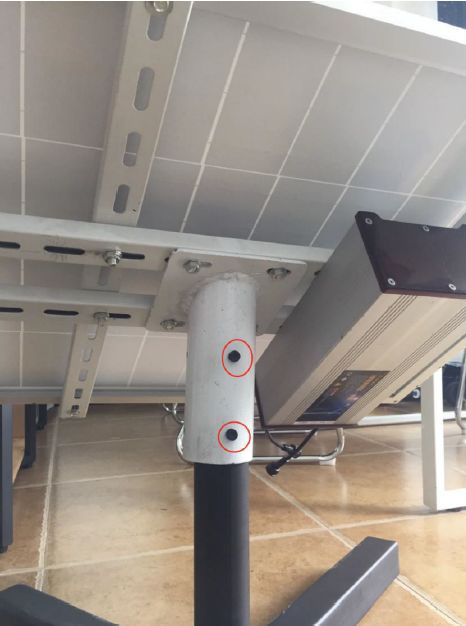 Figure 1: Installing Bolts in the Kit into the Vertical Circular Pole
Lightning Protection
In this document, we will be discussing how to set up your lightning surge protection system whether be your RAK7249 WisGate Edge Max situated outdoor or indoor. Such protection system must be taken into consideration to ensure a fully functional Gateway without interruption or damage from the lightings.
 Figure 1: Full lighting-protection Set-up Diagram
Outdoor Surge Protection System
Antenna Grounding
RAKwireless recommends a lightning arrestor to be installed on all the antenna N-Type terminals (LoRa, LTE, Wi-Fi and GPS). It is recommended to use a 10-AWG or better grounding wire to connect the arrestor to the tower mounted LoRa antenna. The arrestors have to be Female to Male type in order to fit the antenna and housing connectors. Make sure you use a 10 AWG or better wire to connect the screw terminals of the arrestors to the grounding rail mounted on the building wall (grounding bar in case of field deployment as in the picture).
Gateway Grounding
Additionally, it is recommended to use another 10 AWG or better grounding wire to connect the screw terminal on the bottom right side of the Gateway casing to the grounding rail (bar).
No additional protection for the Ethernet cabling is required at the Gateway side. There is a surge protection system built-in (GDT + Anti-surge resistor).
Indoor Surge Protection
For the purpose of protecting the indoor equipment and circuitry connected to the Gateway you need to install an Ethernet port SPD lightning arrester. It should be positioned along the cabling connecting the Gateway to the PoE injector. Make sure you connect its grounding wire terminal to an appropriate building grounding point. Thus your PoE injector and network switch/router should be surge protected. Please refer to the images in the diagram below for the Outdoor and Indoor portion of the surge protection system. Should you fail to adhere to the recommendations in this document RAKwireless carries no responsibility for any damage your equipment incurs due to lightning strike!
Recommended Equipment
Lightning Arrestor for the LoRa, LTE, and Wi-Fi antennas
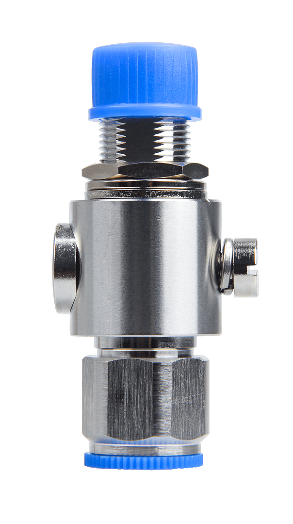 Figure 1: Lightning Arrestor for LoRa , LTE and Wi-Fi Antennas
This is a surge protective device for securing transceivers against over-voltage and surge current induced by bolts of lightning. RAKwireless recommends installing lightning arrestor on all N-type antenna terminals including LoRa, LTE, and 2.4G Wi-Fi antennas.
Lightning Arrestor for the GPS Antenna
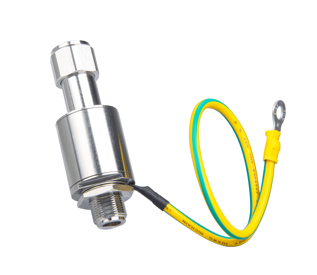 Figure 1: Lightning Arrestor for GPS
This lightning arrestor connects between antenna and GPS receiver. A surge protection device for securing transceiver against transients, over-voltage, and surge currents induced by bolts of lightning.
For the purpose of protecting the indoor equipment and circuitry connected to the gateway, you need to install an Ethernet port SPD lightning arrestor.
By adopting a high pass filter, this product can effectively suppress the low-frequency interference induced by lightning while letting through the GPS signal with low insertion loss. A transient suppression device (TVS) and a gas discharge tube (GDT) is adopted for the protection of the DC feed circuit.
Antenna Feeder Line
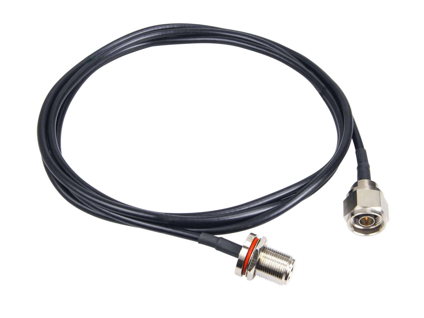 Figure 1: Antenna Feeder Line
Antenna Feeder Line for RAK7249 Lightning Protection. This antenna feeder line is an NJ-NF adapter cable with a length of 1.5m. It is an RG8 coaxial cable with N-type connector as the antenna feeder.
Signal Surge Protective
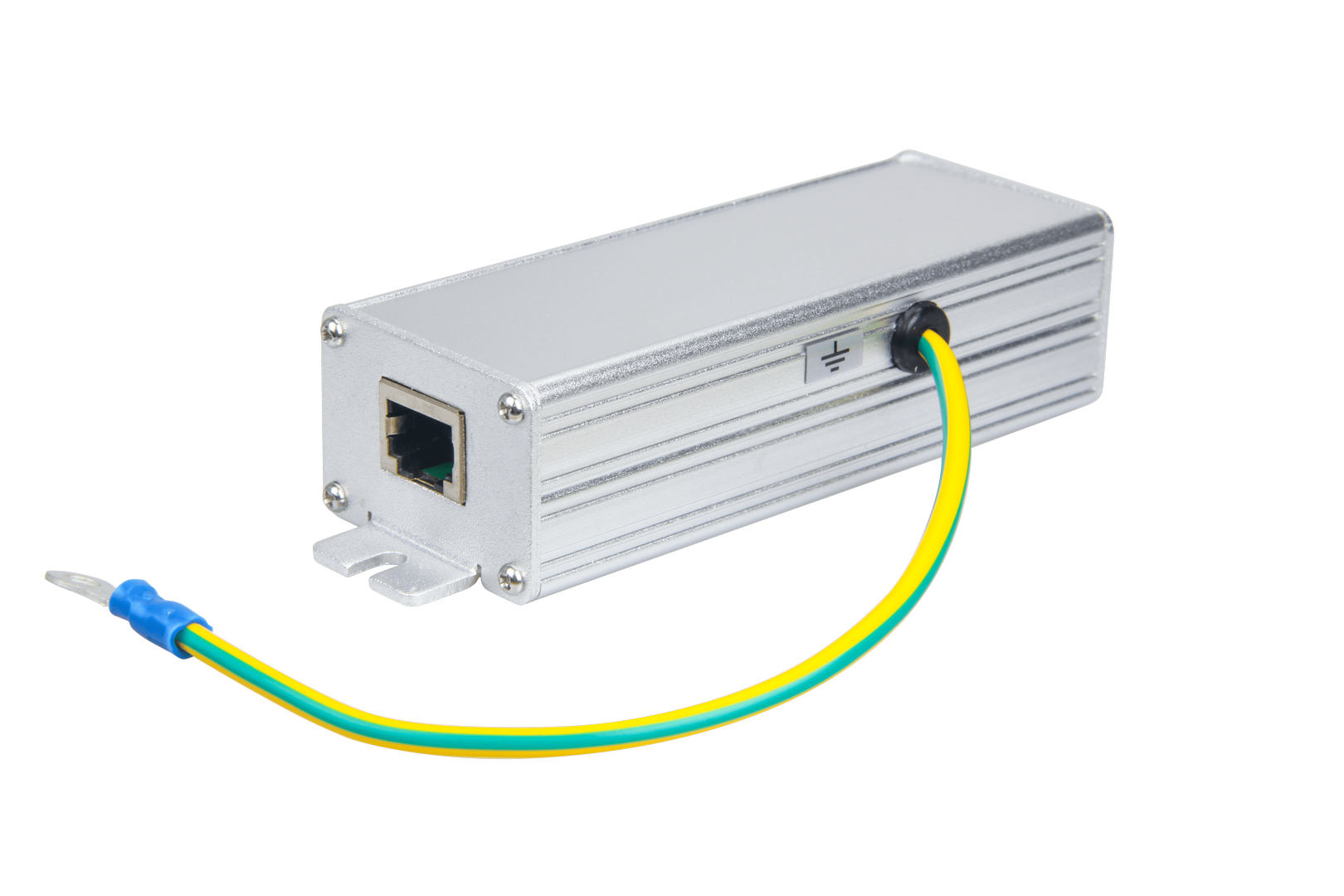 Figure 1: Signal Surge Protective Device
This surge protective device is suitable to Category 6 cable or Class E cable for protection of equipment from surge and over-voltage induced by lightning or produced in the inner systems. It is widely used in office and industry comprehensive network wiring projects or the similar telecommunication applications, such as Gigabit Ethernet, ATM, ISDN and VoIP systems.
High performance chips with smallest parasitic capacitance are adopted in the product, all line protection for the 8 lines, fast response, giving it a ideal choice for protection of lightning effect.
Multiple stage protection structure provides good protection of lightning effect, the tolerable lightning impulse current is 10 kA(between 8 lines in total to the PE ), the product complies with the related international and domestic standards.
Ethernet Cabling
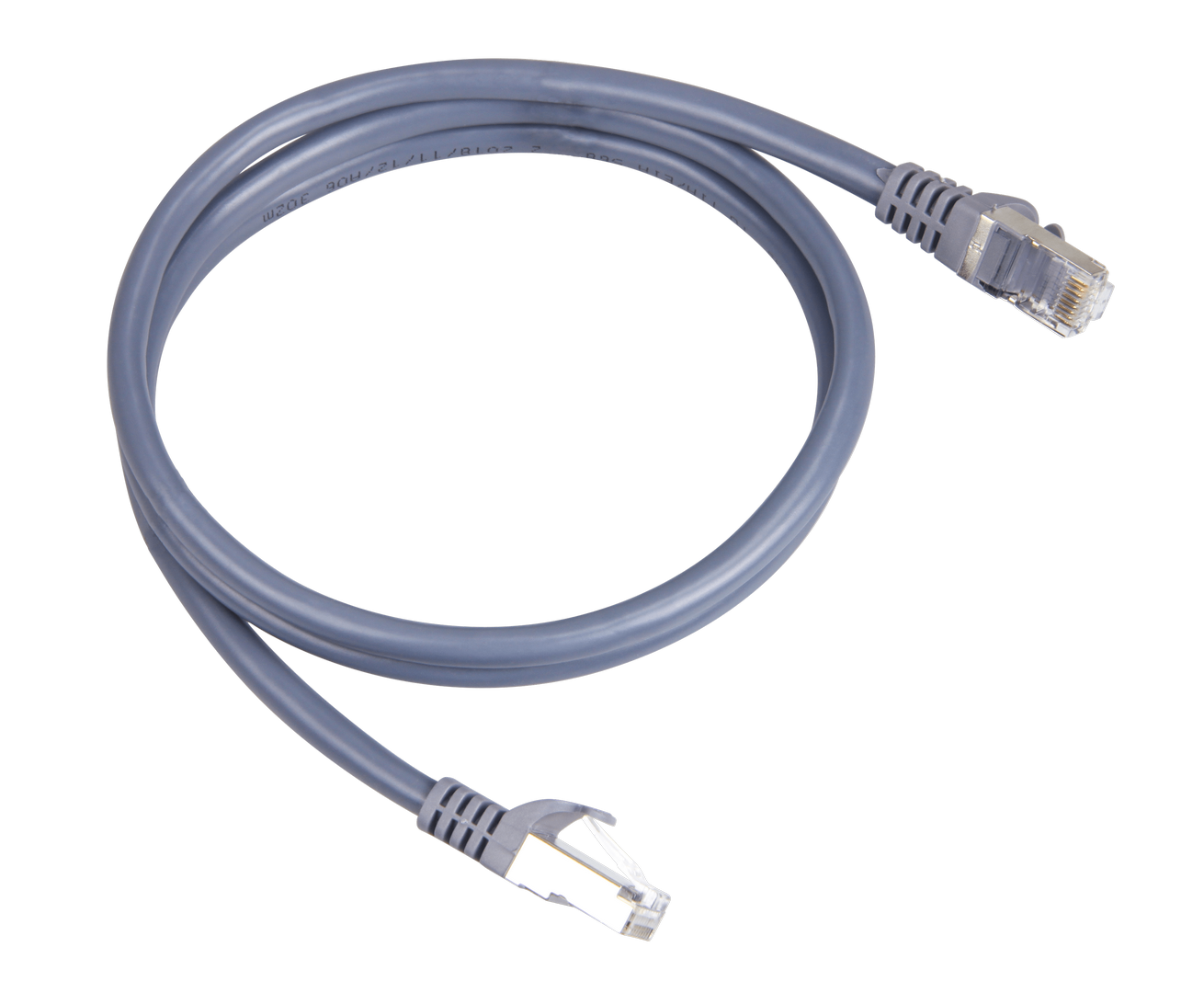 Figure 1: Ethernet Cabling
CAT5 Ethernet Cable for outdoor surge protection system. It is used for connections between the PoE injector, Ethernet SPD, router/switch, and the Ethernet/PoE port on RAK7249. The length of this product is 1 meter.
Power on the Gateway
In this section, it is assumed that you have read and performed the procedures listed in the outdoor-deployment Category. Listed below are the individual sections for you to read depending on your Gateway application:
- Attach the antennas
First and foremost screw on the antennas. All 5 of them should be installed (WiFi, LoRa, LTE-DIV, LTE-MAIN on the top, and GPS on the bottom) same with the image shown below.
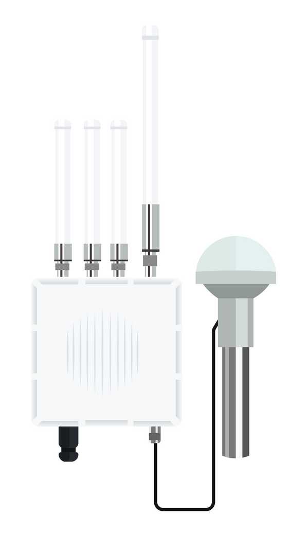 Figure 1: RAK7249 WisGate Edge Max with the Antennas installed
Do not power the device if any antenna port has been left open. In case you do not desire to use one or more antenna feature, make sure to terminate the port with a 50 Ohm load.
- Power on the Gateway
It is recommended to use a CAT5 Cable to provide power to the Gateway. Attach one end to the PoE injector and the other to the Ethernet Port on the bottom of the casing.
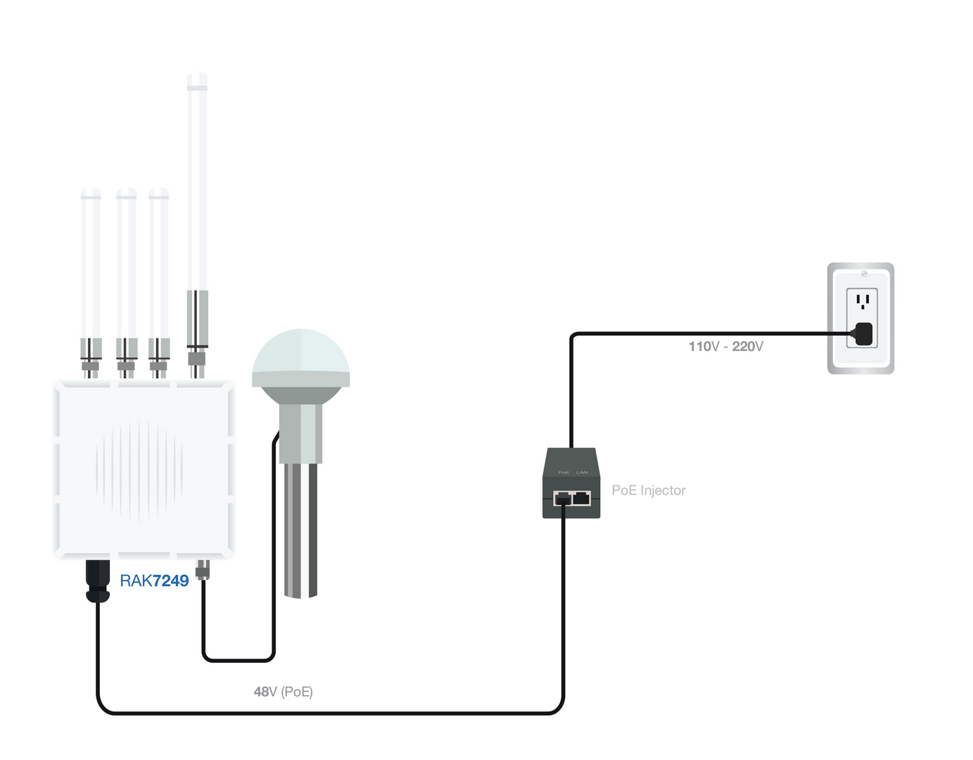 Figure 1: Powering the Gateway using PoE
Access the Gateway
In this section, several ways in accessing the gateway are provided to have different alternatives for you to choose depending on the availability of the requirements needed.
Do not power the device if the LoRa Antenna port has been left open to avoid potential damage in the RAK7249 WisGate Edge Max."
Wi-Fi AP Mode
By default, the Gateway will work in Wi-Fi AP Mode which means that you can find an SSID named like "RAK7249_XXXX" on your PC's Wi-Fi Network List. "XXXX" is the last two bytes of the Gateway MAC address. To access the Web Management Platform, input the IP Address: 192.168.230.1 in your Web browser.
No password is required to connect via Wi-Fi
Using your preferred Web browser, input the aforementioned IP Address and you should see the same Log-in Page shown in the following image. Login the credentials provided below:
- Username: root
- Password: root
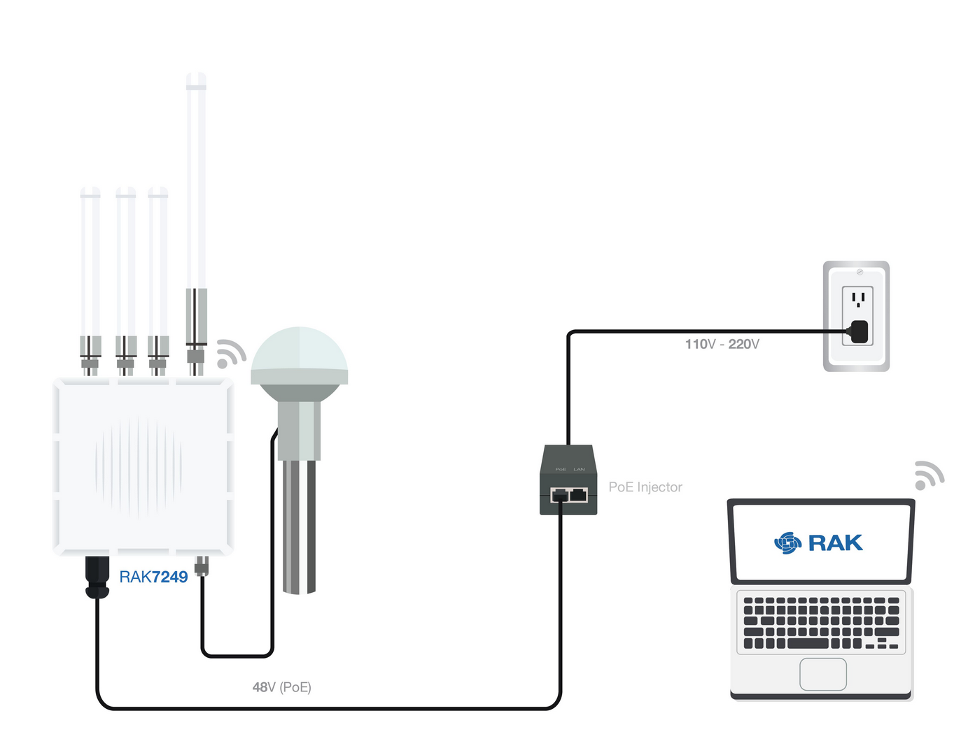 Figure 1: Accessing the Gateway via Wi-Fi AP Mode
WAN Port (Ethernet)
Connect the Ethernet cable to the port marked “ETH” on the Gateway and the other end to the PoE port of the PoE injector. Connect the LAN port of the PoE injector to your PC.
The default IP is 169.254.X.X. The last two segments(X.X) are mapped from the last four bits of the MAC address of your gateway. For example, the last four bits of the MAC address are 0F:01, and the IP address is 169.254.15.1. Make sure to manually set the address of your PC to one in the same network (for example 169.254.15.100). Use the same credentials for the Web UI as for AP mode.
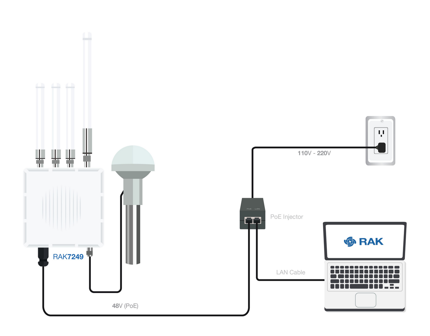 Figure 1: Accessing the Gateway via WAN Port (Ethernet)
Access the Internet
Connect through Wi-Fi
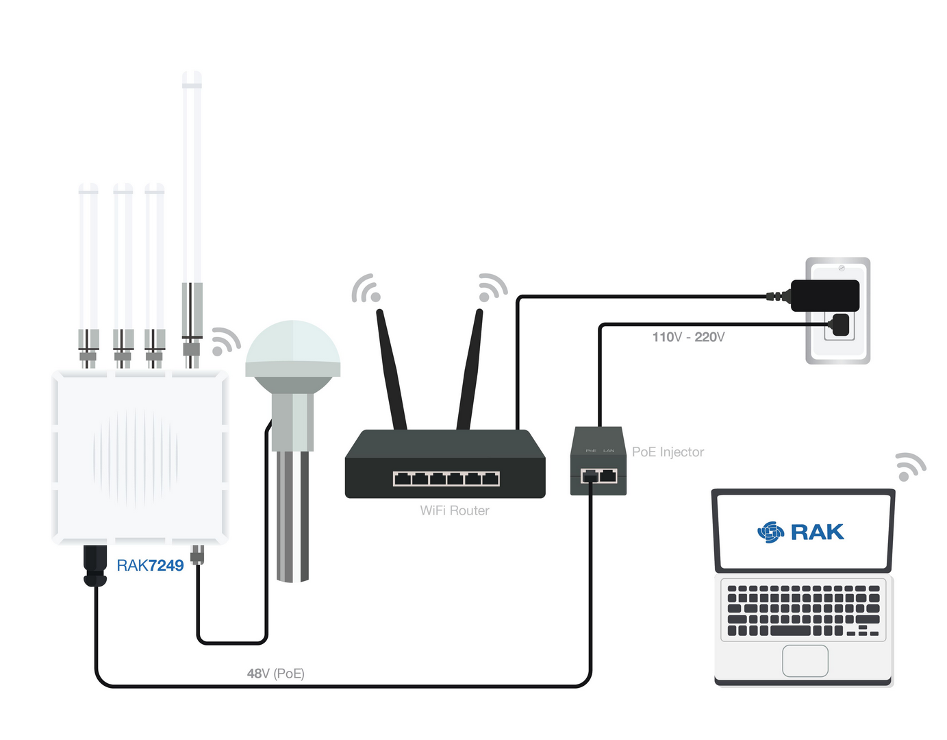 Figure 1: Accessing the Internet using Wi-Fi
Go into the Network>Wi-Fi Menu and make sure to enable the Wireless Client as it is disabled initially. Enter or click "Scan" to choose your ESSSID, select the right Encryption method and enter the correct Key.
 Figure 1: Connect through Wi-Fi Credentials
Assuming you have entered the correct parameter values you should get an IP address assigned by your Wi-Fi router's (AP) built-in DHCP server. You can use this new IP address to log in via a web browser (same way as in AP mode).
Connect through Ethernet/PoE
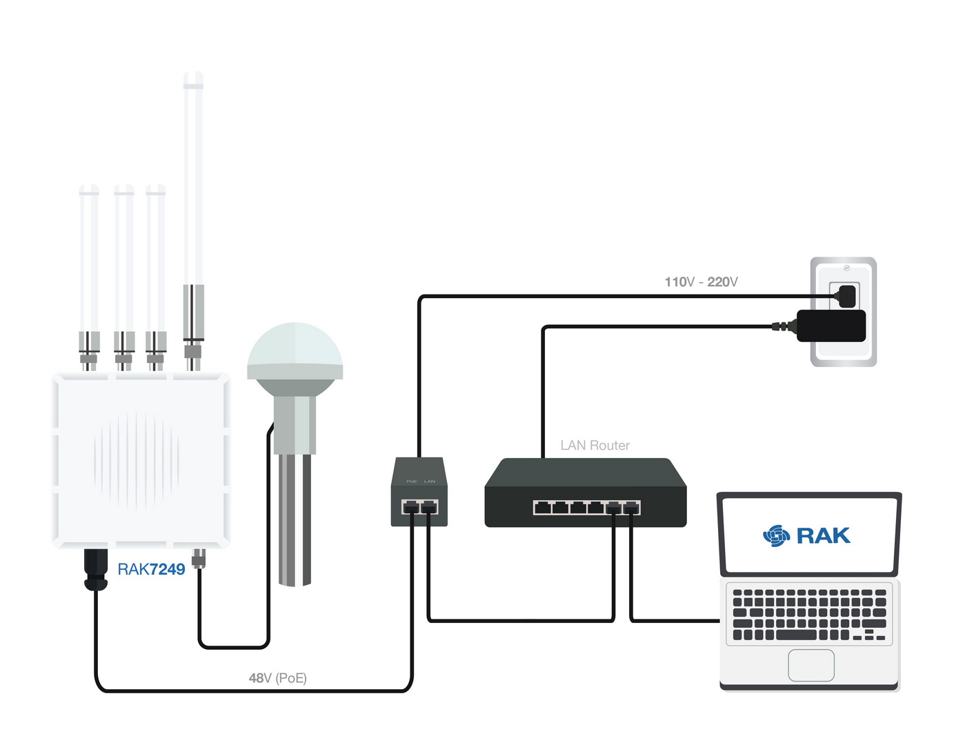 Figure 1: Accessing the Internet through Ethernet
Connect the Ethernet cable to the port marked “ETH” on the Gateway and the other end to the PoE port of the PoE injector. Connect the LAN port of the PoE injector to your router. The router’s DHCP server should assign an IP Address to the Gateway. You can change the default settings below if you wish (details in the User Manual).
 Figure 1: Connect through Ethernet Settings