RAK7391 WisGate Connect Assembly Guide
Indoor Rack Enclosure
- Install the CM4 module. The module does not need to be fixed with screws but it is recommended.
 Figure 1: Install the CM4
- If there should be an M.2 card in your configuration, install it on the back of the RAK7391.
 Figure 1: Install the M.2 card
- Fix the RAK7391 bottom of the lining plate with four M3*6 screws.
 Figure 1: Fix the boar to the lining
- Pass the RF cable/connector through the circular openings in the shell and secure it using the washer and nut. Ensure the pigtails are sufficiently long and that the connector polarity matches your antenna's polarity (SMA or RP-SMA). If these connectors are not needed for your setup, use the provided rubber plugs to seal the openings.
 Figure 1: Fix the antenna connectors
- Install the necessary modules based on your use case. For LoRaWAN concentrators, ensure they are installed in MiniPCIe slots #1 or #2, which support SPI and USB2 interfaces. Slot #3 is equipped with USB3 and PCIe interfaces.
 Figure 1: Add different types of Hats
 Figure 1: Add different types of Hats
- Install the RF cable/connector and LCD on the front panel according to your setup requirements, and secure the display with M2*3 screws. Rubber plugs can be inserted into the spare RF holes. Make sure the pigtails are long enough and that the connector polarity matches your antenna (SMA/RP-SMA).
 Figure 1: Fix the antenna connectors and display
The quantity of included RP-SMA connectors varies depending on the selected product variant.
- Attach the RF cable connectors on the upper cover to the corresponding connectors on the modules and connect the DuPont cable to the socket on the motherboard. Carefully align and secure the upper cover. Close it and fasten it with eight M2.5*5 countersunk screws.
 Figure 1: Connect the cables
 Figure 1: Close the enclosure
- If your setup doesn't require WisBlock modules, install the small cover plate at the side window opening and fix it with two M2.5*5 countersunk screws.
 Figure 1: Close the WisBlock access point
- Install the LoRa, WiFi, and LTE antennas based on your setup requirements.
- LoRa Antenna: Install the LoRa antenna to the appropriate LoRa connector.
- WiFi Antenna: Install the WiFi antenna, which is marked with a blue sticker, to the designated WiFi connector on the gateway.
- LTE Antenna: Install the LTE antenna, which is marked with a gray sticker, to the designated LTE connector on the gateway.
Indoor Desktop Enclosure
- Fix the plate to the bottom of the enclosure with four M3*4 screws.
 Figure 1: Fix the plate to the bottom of the enclosure
- If your configuration includes an M.2 card, install it on the back of the RAK7391.
 Figure 1: Install the M.2 card
- Fix the RAK7391 board to the plate with four M3*6 screws.
 Figure 1: Fix the board to the plate
- Install the necessary modules based on your use case. For LoRaWAN concentrators, ensure they are installed in MiniPCIe slots #1 or #2, which support SPI and USB2 interfaces. Slot #3 is equipped with USB3 and PCIe interfaces.
 Figure 1: Add different types of modules
 Figure 1: Add different types of modules
- Prepare the front and back panels by adding the RF cable/connectors and the OLED screen as needed. Make sure the pigtails are long enough and that the polarity of the connector matches the polarity of your antennas (SMA/RP-SMA). Rubber plugs can be used to seal unused antenna holes.
 Figure 1: Prepare the front panel
 Figure 1: Prepare the back panel
The quantity of included RP-SMA connectors varies depending on the selected product variant.
- Fix the front and back panels to the bottom of the casing using two M2.5*8 screws to fix each one. Connect all the cables to the corresponding connectors.
 Figure 1: Attach the front and back panels
- Fix the top cover using twelve M2.5*8 screws.
 Figure 1: Attach the top cover
- If your setup doesn't require WisBlock modules, install the small cover plate at the side window opening and fix it with two M2.5*5 countersunk screws.
 Figure 1: Close the WisBlock access point
- Stick the four anti-slip pads.
 Figure 1: Add anti-slip pads
- Install the LoRa, WiFi, and LTE antennas based on your setup requirements.
- LoRa Antenna: Install the LoRa antenna to the appropriate LoRa connector.
- WiFi Antenna: Install the WiFi antenna, which is marked with a blue sticker, to the designated WiFi connector on the gateway.
- LTE Antenna: Install the LTE antenna, which is marked with a gray sticker, to the designated LTE connector on the gateway.
DIN Rail Mounting
A minimum clearance/free space of 180 × 180 mm is required for the device. This measurement does not include antennas directly mounted to the connectors.
For proper airflow and cable management, reserve an additional 10-20 mm clearance on each side.
- Attach the DIN rail mounting clips to the device using four M3*6 countersunk screws.
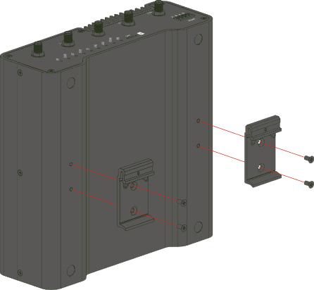 Figure 1: DIN rail mounting clips on the RAK7391
- Mount the device onto the DIN rail.
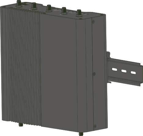 Figure 1: RAK7391 mounted on a DIN rail
Wall Mounting
- Remove the four screws from the device, then attach the mounting brackets using the same screws.
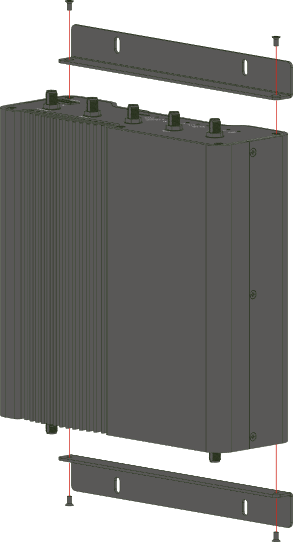 Figure 1: Wall mounting brackets on the RAK7391
- Using a 5 mm drill bit, drill the mounting holes in the wall and insert the wall anchors.
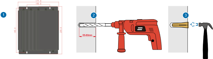 Figure 1: Wall preparation for RAK7391 installation
- Secure the device to the wall using four self-tapping screws.
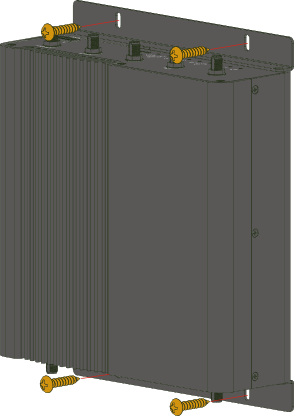 Figure 1: RAK7391 secured to the wall
Outdoor Enclosure
Assembly
- Fix the plate inside of the enclosure using four M3*4 screws.
 Figure 1: Fix the plate
- Install the RF cable/connector in the left antenna connector opening and seal the right one with a plug. Ensure the pigtail is long enough to connect to the designated module. If an external antenna is not needed, plug both openings.
 Figure 1: Add an antenna connector
- Install the CM4 module. While it does not require screws for installation, securing it with screws is recommended for stability.
 Figure 1: Install the CM4
- If your configuration includes an M.2 card, install it on the back of the RAK7391.
 Figure 1: Install the M.2 card
- Fix the RAK7391 on the lining plate with four M3*6 combination screws.
 Figure 1: Fix the board to the plate
- Install the necessary modules based on your use case. For LoRaWAN concentrators, ensure they are installed in MiniPCIe slots #1 or #2, which support SPI and USB2 interfaces. Slot #3 is equipped with USB3 and PCIe interfaces.
 Figure 1: Install additional modules
 Figure 1: Install additional modules
- If using the enclosure's built-in antennas, attach the IPEX connectors to their corresponding positions, including the RF antenna connector. Carefully position the antenna plate along the edge of the bottom shell and secure it with seven M3*6 combination screws.
 Figure 1: Fix the antenna plate
If your setup does not require the built-in GPS, 2 LTE, or 2 Wi-Fi antennas, you can omit installing the antenna plate.
- Close the top cover and secure it with twelve M4*12 combination screws, ensuring the rubber seal is properly positioned. Finally, install the vent valve on the back of the enclosure.
 Figure 1: Close the enclosure
- Close the gateway, ensure proper grounding, and connect it according to your specific setup requirements.
 Figure 1: Final touches
Installation
Instructions on mounting and securing the mounting kit to the enclosure and the bearing pole.
- Fix the device bracket on the bottom of the enclosure with four M6*12 screws.
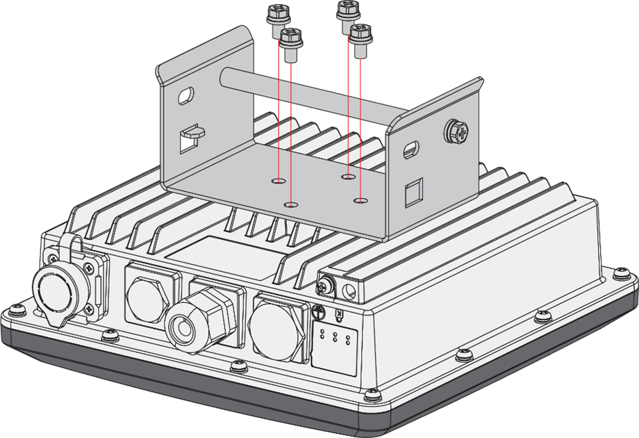 Figure 1: Fix the bracket to the enclosure
- Position and tighten the pole clamps together around the pole with bolts, washers, and nuts.
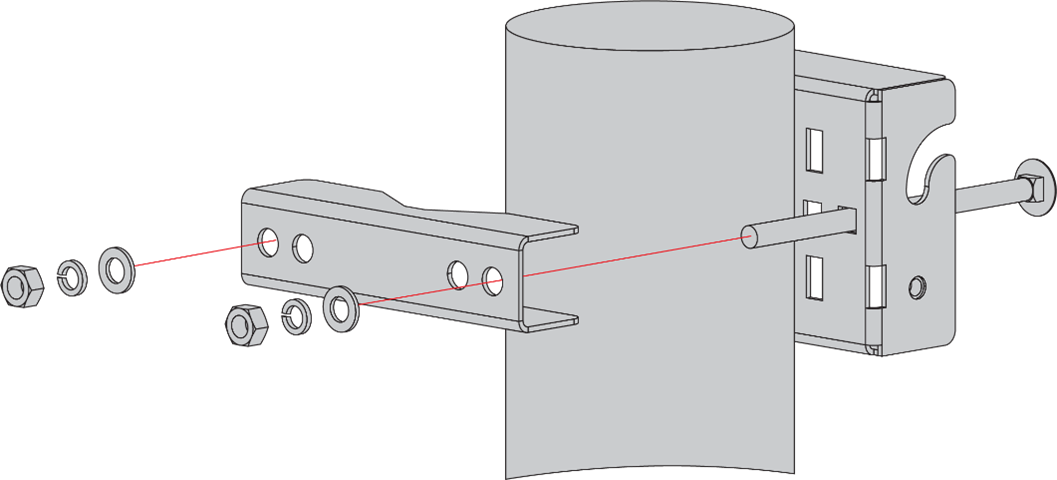 Figure 1: Position and secure the pole clamps around the pole
The brackets support poles with a diameter of 50-100 mm. For poles with a larger diameter, steel strips can be used. Note that steel strips are not included in the standard mounting kit and must be purchased separately if required.
- Hang up the enclosure and fasten it with two M6*12 screws.
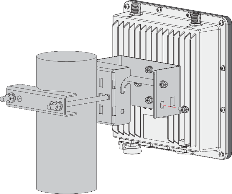 Figure 1: Fix the enclosure to the pole
Connect the PoE Adapter
- Connect the Ethernet cable from the enclosure to the Ethernet port labeled PoE on the adapter.
- Connect an Ethernet cable from your LAN network to the Ethernet port labeled LAN on the adapter.
- Connect one end of the power cord to the adapter. Connect the other end of the power cord to a power outlet.
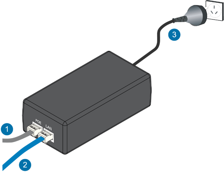 Figure 1: PoE adapter
Weather Protection
To better protect the Ethernet cable gland and the antenna connector from the weather, you need to cover them with PVC tape.
- Clean the surface of the connector to be wrapped. Wrap a layer of PVC tape with a 50% overlap, following the connector's rotation direction. Extend the wrapping approximately 10 mm below the end of the connector.
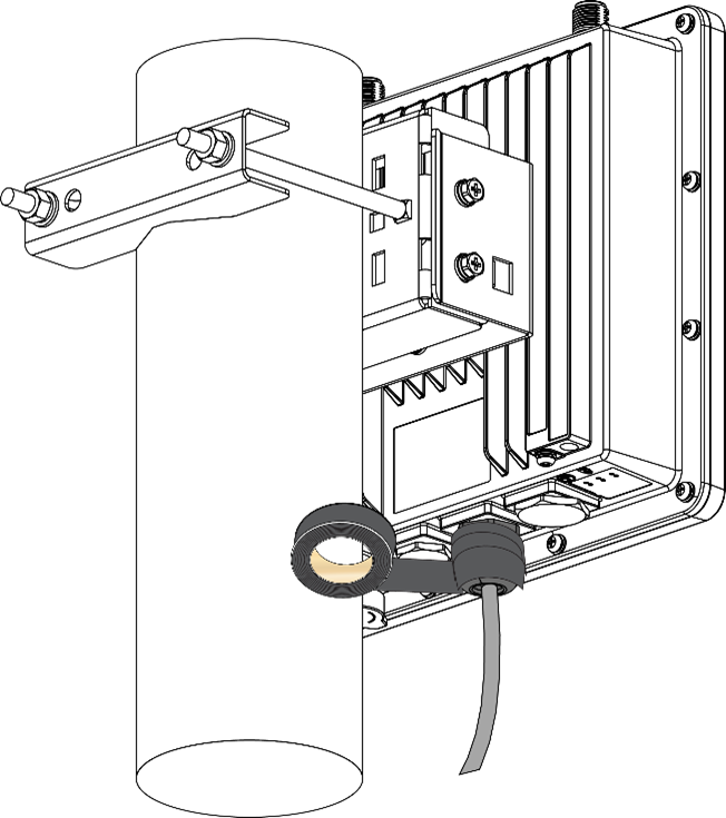 Figure 1: Wrap with PVC tape
- Cut a 50 cm length of waterproof tape and stretch it to double its length. Wrap three layers around the connector with a 50% overlap. Hold the tape firmly in place with your hand for a few seconds to secure it.
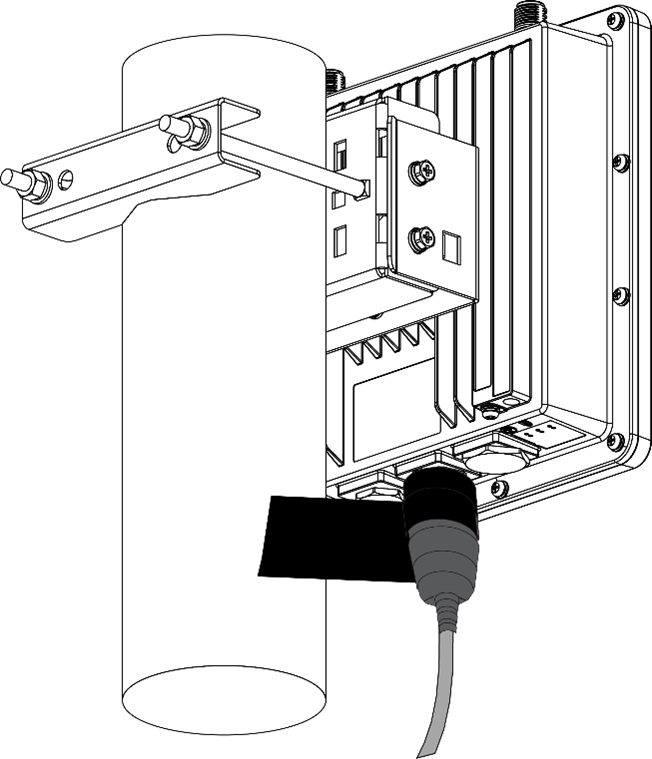 Figure 1: Wrap with waterproof tape
- Wrap three additional layers with PVC tape with natural uncoiling force and a 50% overlap. Make sure to cover the head and the tail of the connector.
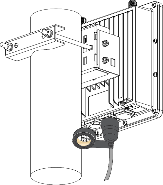 Figure 1: Final PVC wrapping