RAK7590 Field Tester Pad Datasheet
Product Overview
The RAK7590 Field Test Pad is a handheld device designed for indoor and outdoor LoRaWAN network testing and deployment verification. It enables real-time measurement of uplink and downlink signal quality (RSSI, SNR) and packet loss rate, helping users evaluate network coverage during installation or maintenance.
This device features a large LCD screen for on-device parameter configuration and test result visualization. With its built-in GPS module, users can associate test data with precise location information and view signal distribution on the map. It also supports test report viewing and downloading for efficient data tracking and comparison.
The RAK7590 works with the Field Test Data Processor Extension on WisGateOS 2, which performs backend data parsing and analysis to deliver a complete LoRaWAN® network testing workflow from data collection to performance evaluation.
Key Features
- Designed based on the Raspberry Pi CM4 platform.
- LoRaWAN® 1.0.3 compliant, supporting RU864, IN865, EU868, US915, AU915, KR920, and AS923-1/2/3/4 bands.
- Supports TTN, ChirpStack, AWS IoT Core for LoRaWAN, and private networks using WisGateOS 2 Built-in Network Server (no Internet required).
- Map display with offline map support, enabling field testing in areas without Internet connectivity.
- Supports manual location labeling for marking specific test points.
- Heatmap visualization for quick signal-quality assessment.
- Built-in test report viewer with export options for data comparison and analysis.
- Equipped with a 20,000 mAh (3.7 V) rechargeable lithium battery, providing over 11 hours of operation on a full charge.
- Supports dual power modes: USB Type-C external power input or internal rechargeable battery.
- Built-in GPS, Wi-Fi, and BLE antennas.
- External LoRa® antenna for enhanced RF performance.
- Supports OTAA activation and Class A modes.
- Integrated RTC with up to 5 years of operation using its auxiliary power source.
- Features a 7-inch, 1024 × 600 resolution LCD screen.
Specifications
Interfaces
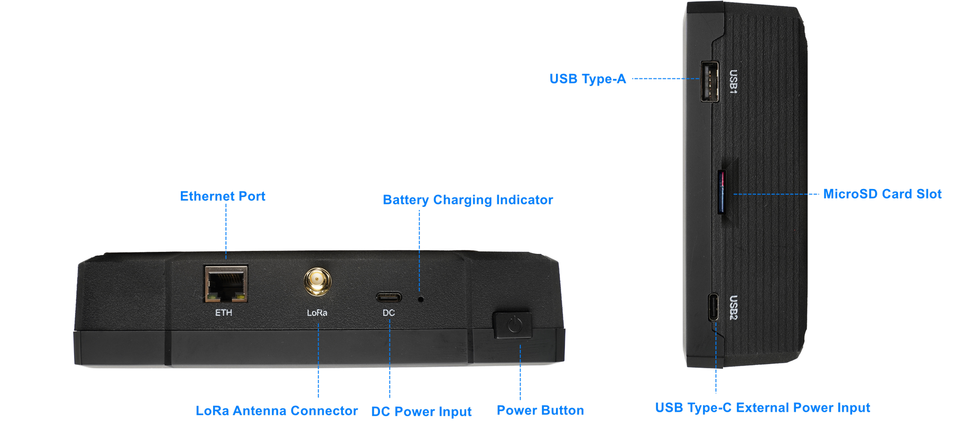 Figure 1: RAK7590 Physical Interface
| Interface | Description |
|---|---|
| Power Button | Switch battery power on/off. The USB Type-C power source is not controlled by this switch. |
| Battery Charge Indicator | The red light is on when the battery is charging, and off when the battery is not charging. |
| DC Power Input | Supports 5V/3A power input. Provides power to charge the battery. |
| LoRa Antenna Connector | SMA connector for connecting the LoRa antenna, supporting LoRaWAN communication. |
| Ethernet Port (ETH) | 10/100/1000M Ethernet RJ45 port, used wired network connection for CM4 |
| USB 1 | USB Type-A port for connecting external USB devices ,such as USB flash drives or Keyboard |
| MicroSD Card Slot | Slot for inserting a MicroSD card that contains the device's firmware. This card is essential for the device's operation and must not be removed during normal use. |
| USB 2 | USB Type-C external power input (5 V, ≥2 A recommended) for powering the device. Does not charge the battery. |
Main Display
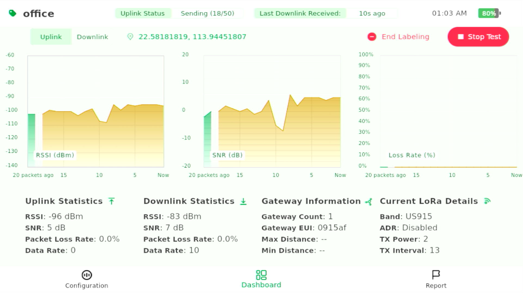 Figure 1: RAK7590 Screen
| Parameter | Description |
|---|---|
| Test Label | Displays the test label. NULL means no label is applied. If a labeling test is being conducted, the input label will be displayed here. |
| Uplink Status | Displays the status of uplink transmission: - Join Success: Device successfully joined the network. - Join Failed: Device failed to join the network. - Send Success: Packet sent successfully. - Send Failed: Packet failed to send. - Sending (x/50):Indicates the number of uplink packets sent during the labeling test, out of the total being sent. - Idle: Device is not actively communicating. |
| Last Downlink Received | Shows the time since the last downlink packet was received (e.g., "XXs ago"). - Green text: Last uplink was successful. - Red text: Last uplink failed. |
| System Time | Displays the current system time. |
| Battery Level | Shows the battery percentage of the device. |
| Uplink/Downlink RSSI/SNR/Packet Loss Graph | Displays the real-time graph of RSSI, SNR, and Packet Loss Rate for the last 20 packets. Switch between Uplink and Downlink by clicking the tabs. |
| GPS Signal | Displays GPS coordinates if available. If there is no GPS signal, it will show No GPS. |
| Start/End Labeling | Button to start or end the labeling test. Clicking Start Labeling begins the test, and once the test is running, the button changes to End Labeling to stop the test. |
| Start/Stop Test | Button to start or stop the test. Clicking Start Test begins the non-label test. Once the test is running, the button changes to Stop Test to stop all ongoing tests. |
| Uplink Statistics | Displays radio signal quality metrics from the device to the gateway: - RSSI (Received Signal Strength Indicator) - SNR (Signal-to-Noise Ratio) - Packet Loss (Percentage of uplink packets lost) - Data Rate (The speed of data transmission, typically measured in bits per second) |
| Downlink Statistics | Displays radio signal quality metrics from the gateway to the device via LinkCheck mode: - RSSI (Received Signal Strength Indicator) - SNR (Signal-to-Noise Ratio) - Packet Loss (Percentage of downlink packets lost) - Data Rate (The speed of data transmission, typically measured in bits per second) |
| Gateway Information | Information about the connected gateway: Gateway Count: Displays the number of gateways that received the uplink. Gateway EUI: Shows part of the EUI (unique ID) of the nearest gateway to help identify it easily. Max Distance: Farthest gateway (minimum unit: 250 meters). Min Distance: Nearest gateway (minimum unit: 250 meters). Note: GPS must be available for distance calculation. |
| Current LoRa Details | Shows current LoRa settings and configuration: Band: The LoRa frequency band being used. ADR (Adaptive Data Rate): Indicates whether ADR is enabled or disabled. TX Power: The transmission power setting, typically expressed in dBm. TX Interval: The interval between transmissions, typically expressed in seconds. |
RF Characteristics
LoRaWAN Operating Frequencies
The RAK7590 Field Tester for LoRaWAN supports the regional bands shown in the table below. When purchasing this device, pay attention to specifying the correct variant for your region.
| Region | Frequency (MHz) | RAK7590 Field Tester for LoRaWAN |
|---|---|---|
| Russia | RU864 | 8xx MHz version |
| India | IN865 | 8xx MHz version |
| Europe | EU868 | 8xx MHz version |
| North America | US915 | 9xx MHz version |
| Canada | US915 | 9xx MHz version |
| Australia | AU915 | 9xx MHz version |
| Korea | KR920 | 9xx MHz version |
| Asia | AS923-1/2/3/4 | 9xx MHz version |
Antenna
| Antenna Type | Frequency Range | Antenna Gain | LNA Gain | Efficiency |
|---|---|---|---|---|
| GPS Antenna | 1575.42 – 1602 MHz | 0.6 dBi | 22 dB | 42% |
| Wi-Fi Antenna | 2400 – 2500 MHz | 3.12 dBi | — | 79.95% |
| BLE Antenna | 2400 – 2500 MHz | 3.12 dBi | — | 79.95% |
Electrical Characteristics
Power Supply
| Item | Specification |
|---|---|
| DC Power Input | 5 V / 3 A (for normal and fast battery charging) |
| USB 2 (Type-C) | 5 V / 2 A (provides power to the device but does not charge the battery) |
| Power Usage Recommendation | - For indoor configuration or static use, you can turn off the battery and power the device directly via USB Port 2. - Use the built-in battery when external power is not accessible (outdoor/mobile). |
Power Consumption
| Item | Specification |
|---|---|
| Maximum Power Consumption | 7.3 W (continuous LoRa TX + GPS acquisition mode) |
| Power Consumption After Shutdown | Battery standby current: ~0.6 mA |
| Long-term Storage Time | Up to 3 years powered off after a full charge |
Battery & Charging
| Item | Specification |
|---|---|
| Battery Capacity | Built-in 20,000 mAh @ 3.7 V rechargeable lithium battery |
| Battery Runtime | Operates for over 11 hours on a full charge |
| Charging Time | ~10 hours from low battery to full charge (using recommended power adapter) |
| Charging Recommendation | For battery charging, always use the DC 5V/3A input. |
Environmental Characteristics
The table below lists the operation and storage temperature requirements.
| Parameter | Min. | Typical | Max. |
|---|---|---|---|
| Storage Temp. Range | -20° C | +25° C | +60° C |
| Operation Temp. Range | -20° C | +25° C | +40° C |
Mechanical Characteristics
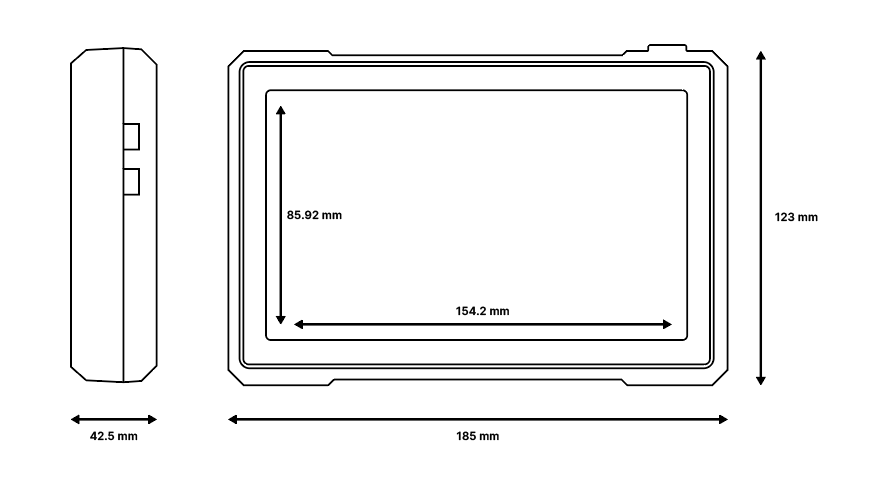 Figure 1: Mechanical characteristics
Firmware
Download the latest firmware version of RAK7590 via the RAK Wireless Downloads.