RAK7590 Field Tester Pad LoRaWAN Network Setup
This guide outlines the necessary steps to configure the LoRaWAN network and prepare devices for field testing.
Test Site With RAK Gateway Deployed
Applicable Scenarios
A test site with an existing RAK gateway usually falls under:
- LoRaWAN network acceptance testing
- Ongoing project maintenance checks
- Installation quality verification and adjustments
- Troubleshooting RF/coverage issues caused by environmental changes (e.g., new buildings, obstacles)
- Evaluating optimal sensor placement within an existing network
Network Setup Approach
Based on the LNS configuration of the on-site gateway, choose the corresponding network setup procedure to ensure your LoRaWAN network is properly prepared in advance.
Cloud LNS Configuration
If the on-site gateway is connected to a cloud-based LoRaWAN Network Server (LNS), refer to the following configuration guides.
- Verify the gateway’s operational status remotely
- Ensure the gateway is powered and online
- Confirm uplinks are being forwarded normally through the LNS
- Confirm the gateway’s LNS configuration
- Check frequency plan and server address
- Register the Field Tester Pad on the same LNS
- Configure the Pad's LoRaWAN parameters under Configure LoRa Settings on the Field Tester Pad
- Register the Field Tester Pad on the LNS by following the instructions in Configure LoRaWAN Network Server
- Prepare the Extension configuration
- Complete all server-side settings required by the Field Test Data Processor Extension by following the instructions in Configure Field Test Data Processor Extension
- Prepare any extension-side parameters that will be needed on-site
- On-site: Install and configure the Extension on the gateway
- Download and install extension, refer to How to Add an Extension
- Apply the pre-prepared configuration parameters
- On-site: Start the Field Tester Pad
- Once the Pad joins the LNS successfully, proceed with basic functionality checks.
- On-site: Perform an initial RF check
- Place the Pad directly under the gateway.
- RSSI should be close to 0 (e.g., –15 to –25 dBm)
- SNR should be high (e.g., 15~20 dB)
- Move the Pad away from the gateway, RSSI and SNR should decrease accordingly.
- Place the Pad directly under the gateway.
Switch to Built-in Network Server
For sites with restricted networks, no internet access, or where rapid testing is required. Because the Built-in Network Server must be configured directly on the gateway, all server-side setup is performed on-site.
Follow the procedures in:
- Configure LoRa Settings on the Field Tester Pad.
- Configure LoRaWAN Network Server > Built-in Network Server (WisGateOS 2)
- Configure Field Test Data Processor Extension
Perform an initial RF check
- Place the Pad directly under the gateway.
- RSSI should be close to 0 (e.g., –15 to –25 dBm)
- SNR should be high (e.g., 15~20 dB)
- Move the Pad away from the gateway, RSSI and SNR should decrease accordingly.
Test Site Without RAK Gateway Deployed
Applicable Scenarios
A site without a RAK gateway is typically associated with the following scenarios:
- LoRaWAN network feasibility evaluation
- Pre-project technical survey
- Coverage prediction vs. actual measurement comparison
- Evaluating the optimal placement for gateway installation
Network Setup Approach
- Prepare at least one RAK gateway
- Select a suitable RAK LoRaWAN gateway model for the target environment
- Configure all LoRaWAN network settings in advance. Choose the appropriate LNS deployment based on the site’s expected internet availability.
Follow the procedures in:NOTE
- If the site has internet access, the gateway can be connected to a cloud platform (e.g., TTN, ChirpStack).
- If the site has no internet, configure the gateway to use the Built-in Network Server mode.
- Bring deployment materials to the site
- The pre-configured RAK gateway
- Power supply (or PoE injector)
- Mounting hardware
- A site map, including the planned gateway installation point and testing route
- On-site: Install and power on the gateway
Mount the gateway at the planned location and provide stable power.
NOTE
If a Cloud LNS is used, ensure the gateway has a working internet connection on-site.
- Start the Field Tester Pad
- Power on the Field Tester Pad
- Once the Pad joins the LNS successfully, proceed with basic functionality checks.
- On-site: Perform an initial RF check
- Place the Pad directly under the gateway.
- RSSI should be close to 0 (e.g., –15 to –25 dBm)
- SNR should be high (e.g., 15~20 dB)
- Move the Pad away from the gateway, RSSI and SNR should decrease accordingly.
- Place the Pad directly under the gateway.
LoRaWAN Configuration Guide
This chapter provides general configuration instructions for the Field Tester Pad, LoRaWAN Network Servers (LNS), and gateway extensions.
Configure LoRa Settings on the Field Tester Pad
In this section, you will learn how to configure the LoRa settings on the Field Tester Pad.
- Navigate to the Configuration page from the main screen of the Field Tester Pad.
- On the Configuration page, you will find several fields that allow you to configure:
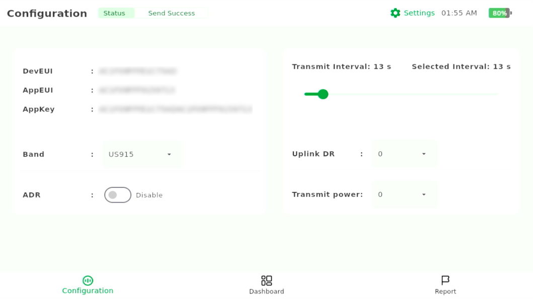 Figure 1: Configuration
- DevEUI: The unique identifier for your device.
- AppEUI: The application identifier.
- AppKey: The key used to securely communicate between your device and the network server.
- Band: The LoRa frequency band (e.g., US915).
- ADR (Adaptive Data Rate): Adjusts the data rate for optimal network performance.
- Transmit Interval: The interval at which the device will transmit data.
- Uplink Data Rate (Uplink DR): Controls the data rate for uplink communication.
- Transmit Power: Sets the transmit power level for the device.
NOTETo change the DevEUI, AppEUI, or AppKey, simply tap on the respective field, and the on-screen keyboard will appear. Enter the new values as needed.
- After editing the settings, tap the Apply button to save and apply the changes.
warning
- When you tap Apply, any ongoing field testing will stop automatically. You will need to manually restart the test from the Dashboard page.
- It may take a few seconds for the changes to be applied to the LoRa chip. Once the changes are successfully applied, a success message will appear on the screen (a toast message).
Configure LoRaWAN Network Server
In this section, you'll configure the LoRaWAN network server (LNS) for your Field Tester Pad based on the network infrastructure available at your test site.
Built-in Network Server (WisGateOS 2)
In the absence of internet access or when a private network is required, you can use the gateway’s Built-in Network Server. This configuration eliminates the need for external network support, enabling devices to register and transmit data through the gateway’s internal server, which is ideal for sites requiring secure or isolated network connections.
Set the Gateway to the Built-in Network Server
This section demonstrates how to connect your RAK gateway to a LoRaWAN Network Server (LNS).
- Log into the WisGateOS 2 web UI.
- Navigate to LoRa > Configuration.
- In the Work Mode section, select Built-in Network Server.
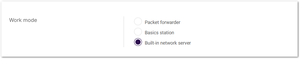 Figure 1: LoRa Configuration Work Mode
- Select the log level and frequency band.
 Figure 1: Log And Frequency Band Configuration
Make sure the frequency band configured on the gateway matches the LoRaWAN Band setting of your Field Tester Pad.
Register the Field Tester Pad
- Navigate to LoRa > Applications tab.
- Click the Add application button (or the add one now link).
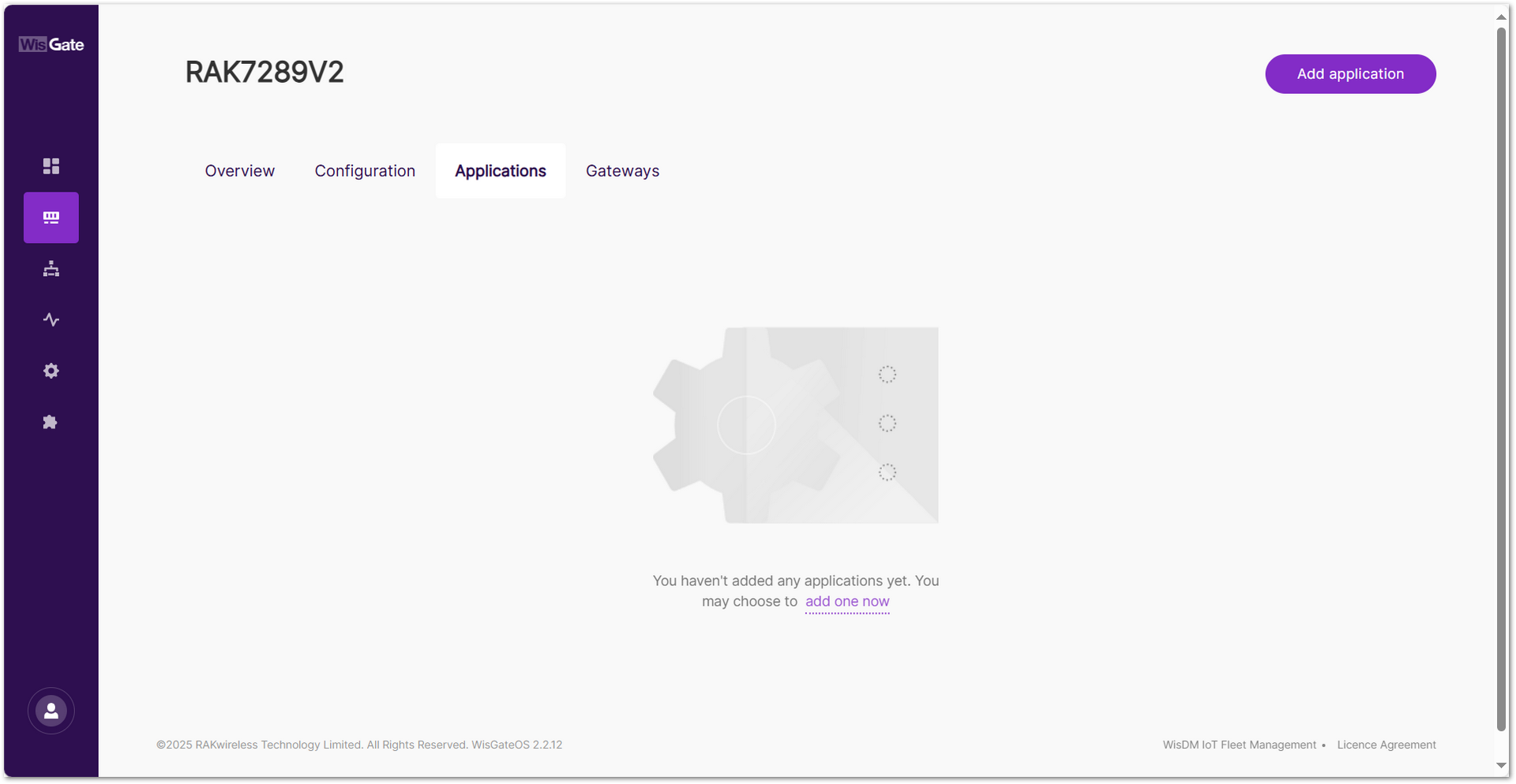 Figure 1: Built LNS Application Menu
 - You will be redirected to the application configuration page. Fill in the following fields:
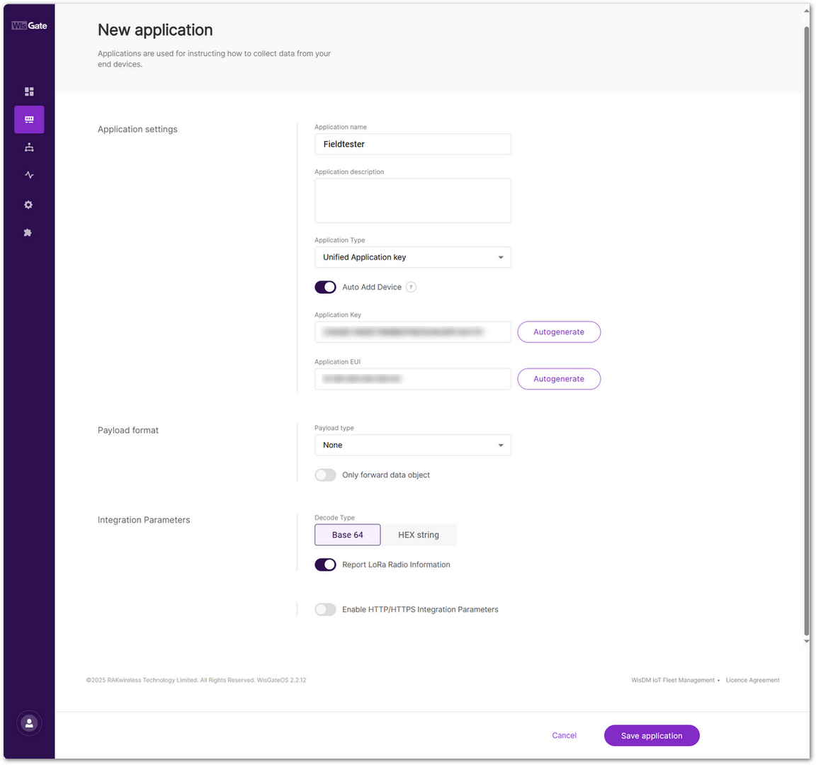 Figure 1: New Application Data Fields
- Application name: Name of the application.
- Application description: Description of the application (optional).
- Application Type
- Unified Application key: All devices will use the same application key.
- Separate Application keys: Each device or group of devices has a unique key.
- Auto Add Device: When enabled, devices with matching AppKey and AppEUI will be added automatically after a successful join request.
- Application Key: Required for Unified Application Key setup.
- Application EUI: Required for automatic device registration when Auto Add Device is enabled.
- Click Save application to complete the creation.
- Once the application is saved, navigate to: Your Application > Configuration. Click End Devices to proceed.
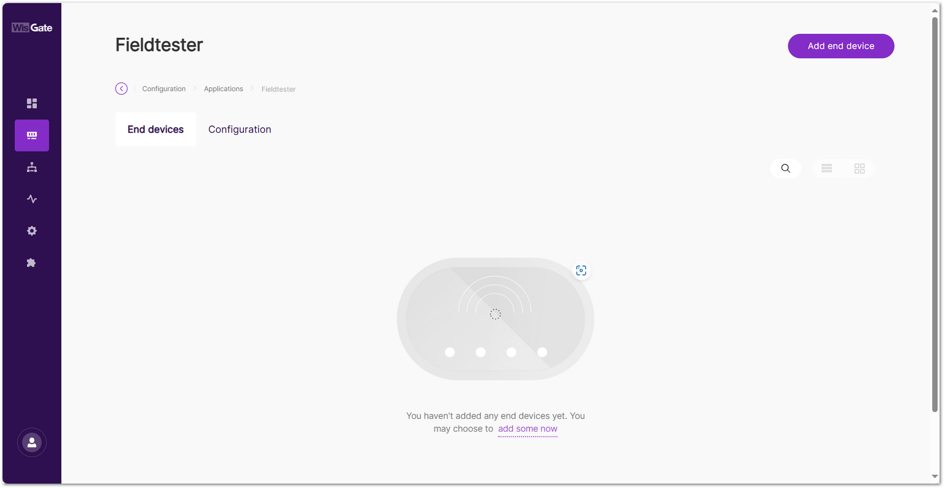 Figure 1: Application End Devices Menu
 - In the End device information interface, fill in the following information.
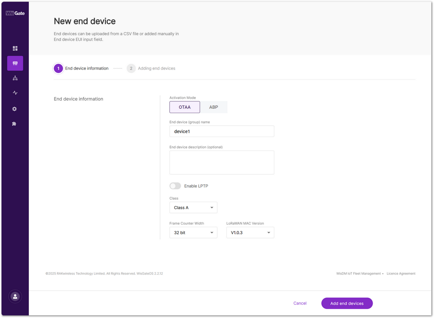 Figure 1: End Device OTAA Configuration
- Activation Mode: Select OTAA.
- End device (group) name: Name of the end device (group).
- End device description (optional): A description of the end device, optional.
- Class: Class A
- Frame Counter Width: Keep the default value.
- Click Add end devices to enter the device adding page.
- In the Adding end devices interface, enter the device EUI in the End Device EUI (main) field and click the Add to End Devices list button.
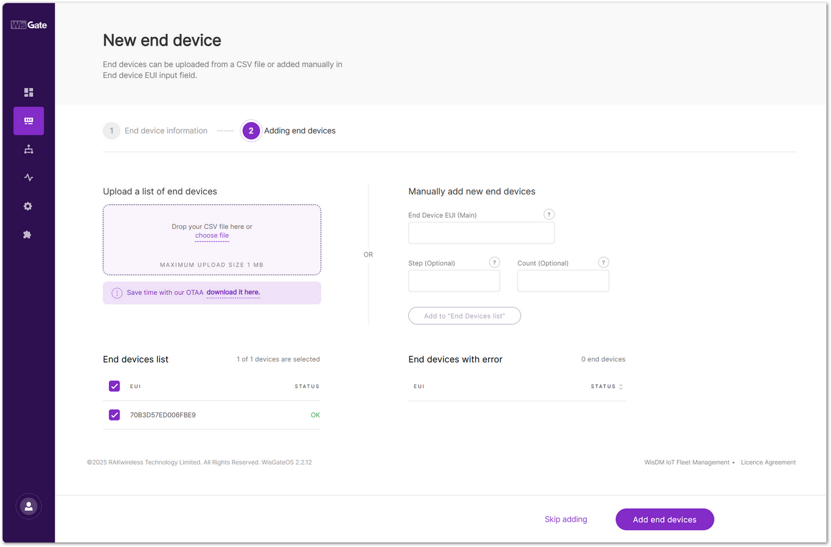 Figure 1: Add New End Device
 - Click Add end devices to add the Field Tester Pad to the application.
- Click Add to confirm and proceed.
- Tap Start Test on the Field Tester Pad dashboard and wait for the device to join the network.
Once registered, the Field Tester Pad will begin sending periodic uplinks to the Built-in LNS.
Now, the device is operating in LinkCheck Mode, as the Field Test Data Processor Extension has not yet been configured. In this mode, the device only displays downlink signal quality metrics.
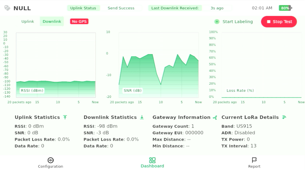 Figure 1: LinkCheck Mode
Next, install and configure the Field Test Data Processor Extension to enable uplink metric reporting.
After the configuration is complete, the device will operate in Field Tester Mode and display both uplink and downlink signal metrics.
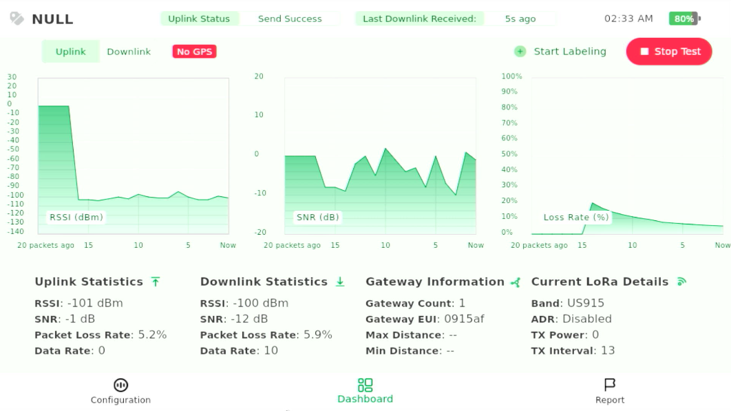 Figure 1: Field Tester Mode
The Things Network (TTN)
Connect the Gateway to TTN
This section describes how to connect and configure a RAK gateway with The Things Network (TTN). TTN supports multiple connection methods, including UDP Packet Forwarder, Basics™ Station (LNS), and Basics™ Station (CUPS). The exact steps depend on your deployment requirements.
To complete the setup, refer to the corresponding official tutorials:
- Registering a RAK Gateway in TTN v3
- Connect RAK Gateways to TTN via UDP Packet Forwarder
- Connect RAK Gateways to TTN Using Basics™ Station (LNS)
- Connect RAK Gateways to TTN Using Basics™ Station (CUPS)
Ensure the frequency band configured on the gateway matches the LoRaWAN Band setting of your Field Tester Pad.
Register the Field Tester Pad
To connect your Field Tester Pad to The Things Network (TTN), a community-based LoRaWAN Network Server (LNS), visit the TTN Console.
- Choose the appropriate cluster for your region. You can either select your country or manually choose the nearest TTN cluster.
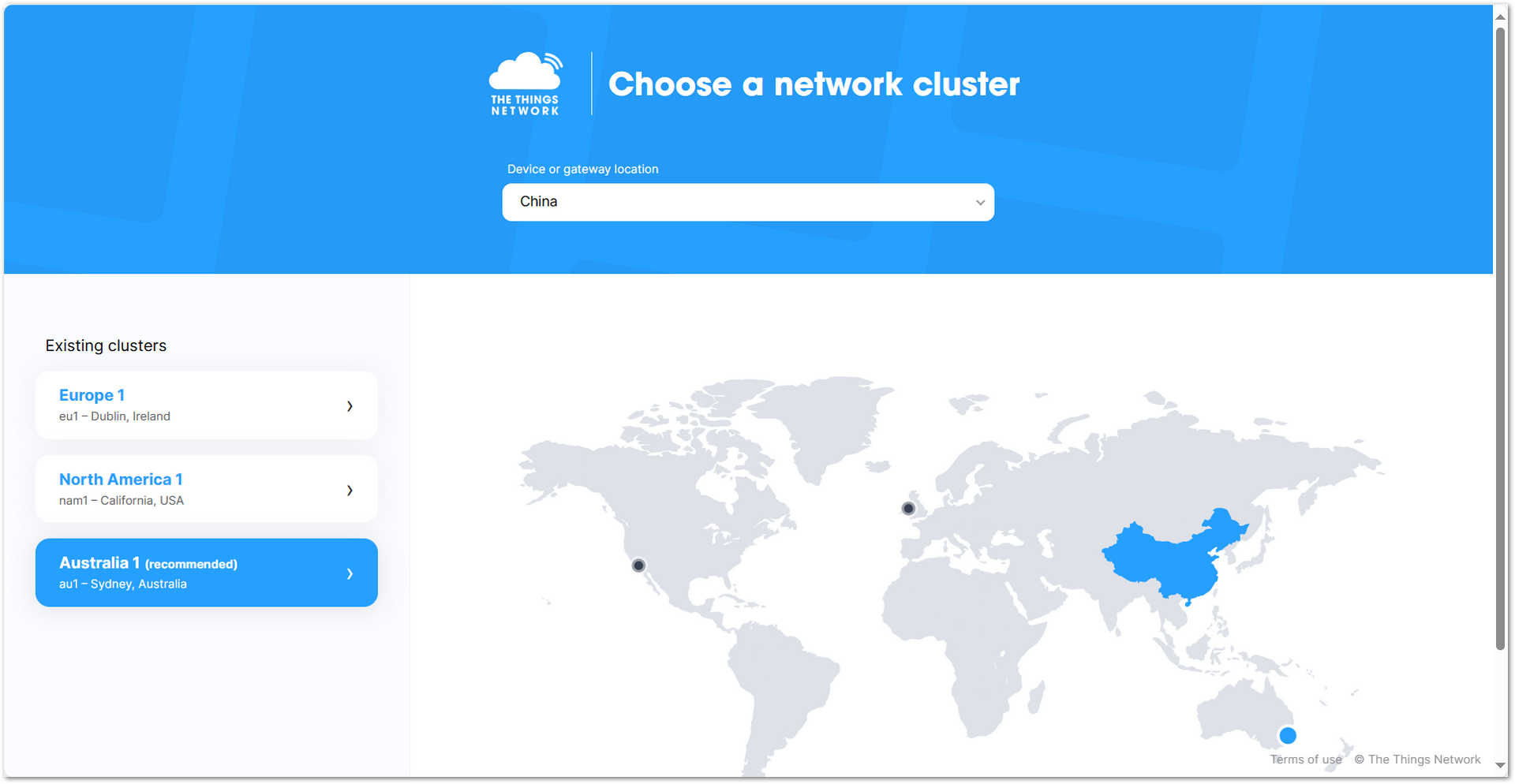 Figure 1: The Things Network Cluster Selection
- On the homepage, click Applications > + Add application
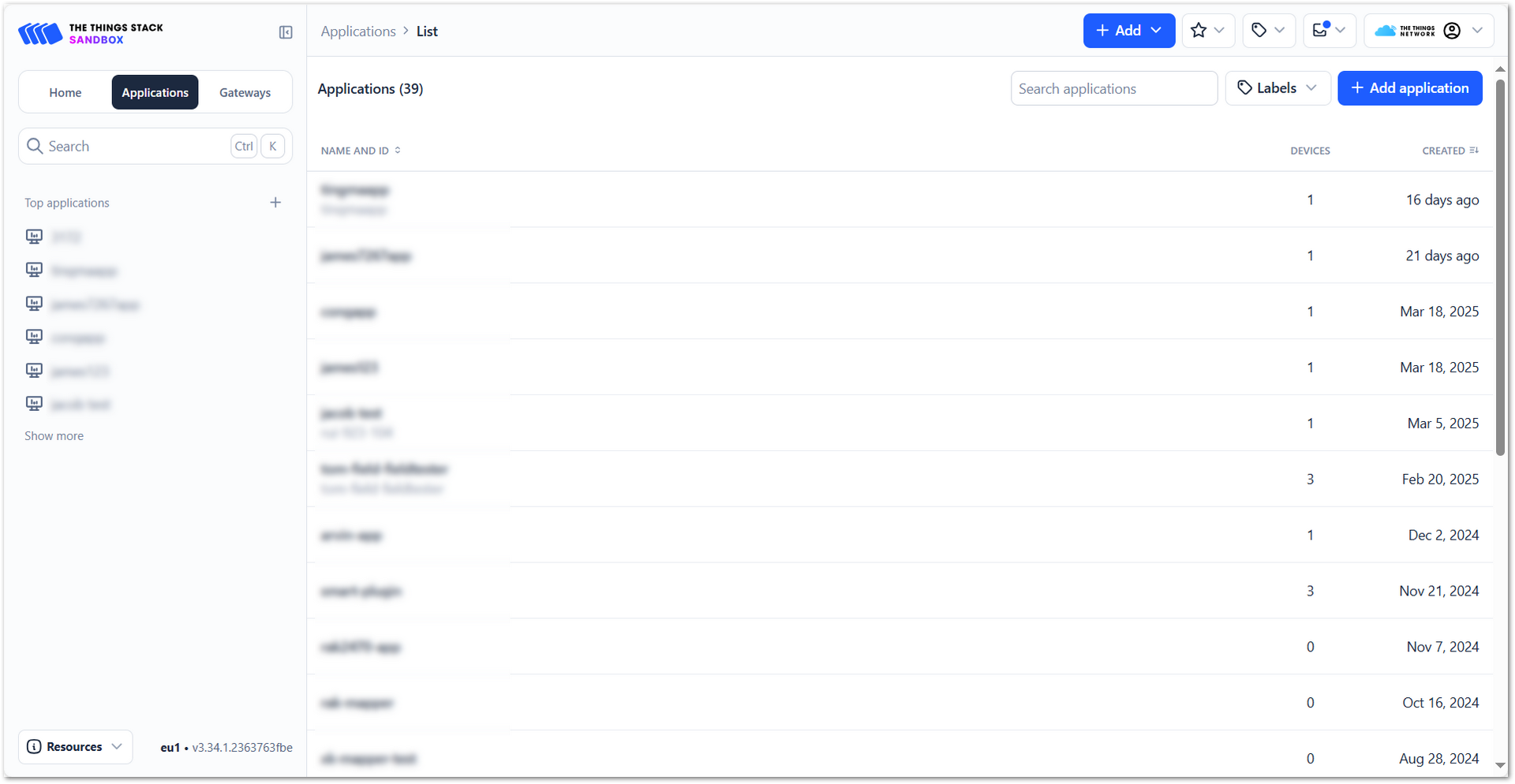 Figure 1: The Things Network Add Application
- Add Application ID, Application name, and Description then click Create application.
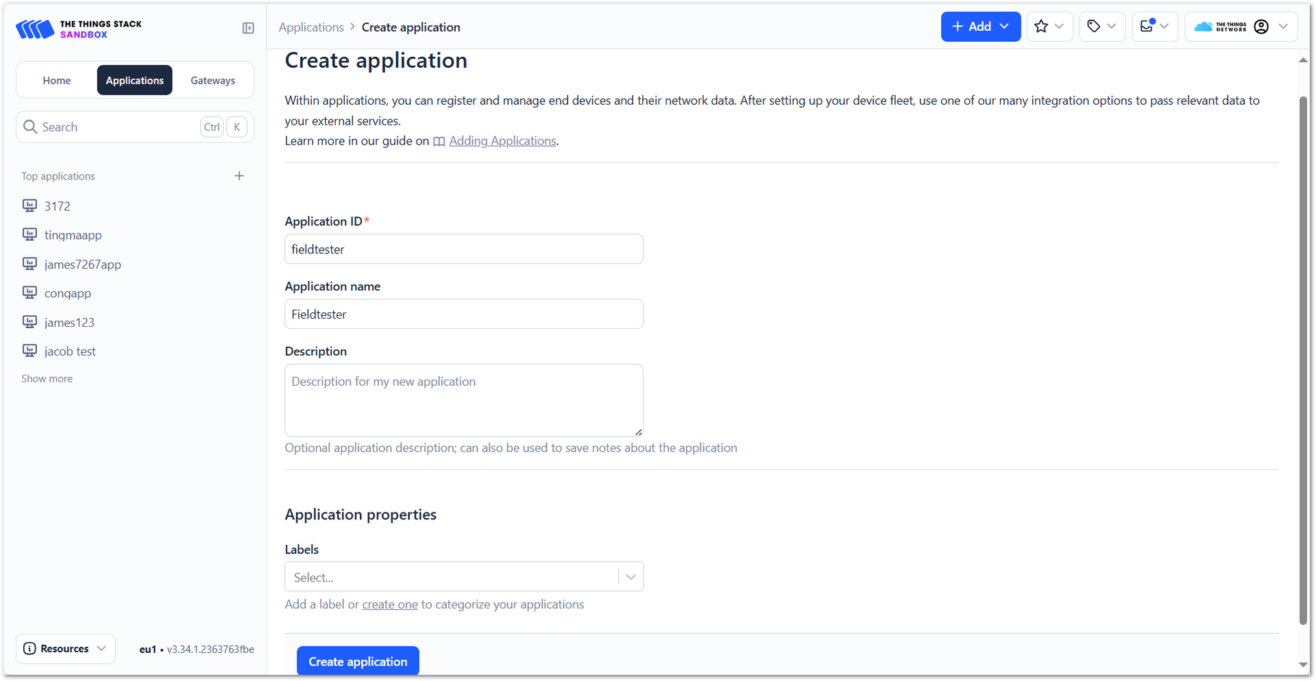 Figure 1: The Things Network Create Application
- Click Register end device within your newly created application.
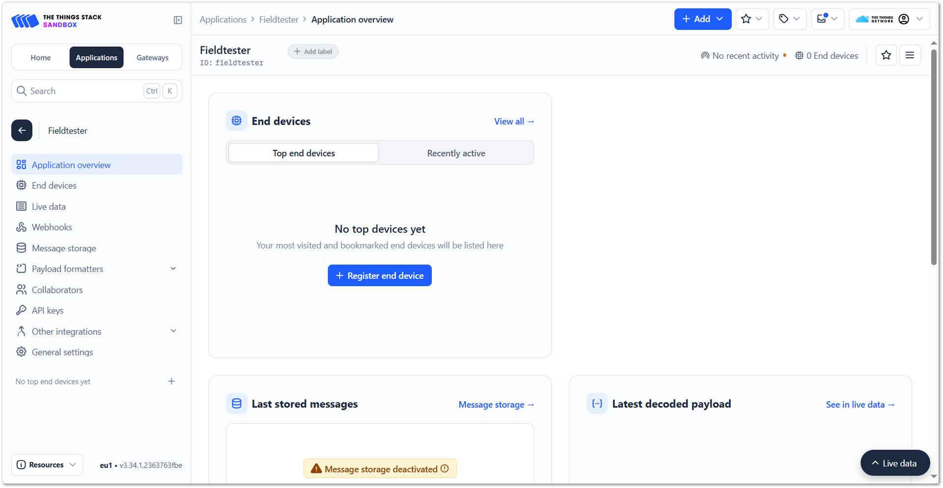 Figure 1: The Things Network Register End Device
- Choose Enter end device specifics manually. This will allow you to add the Frequency plan, LoRaWAN version, Regional Parameters version, and JoinEUI. The values of these parameters depend on the hardware you use. If your device has a preconfigured JoinEUI, you must use it. Click Confirm after putting all the details.
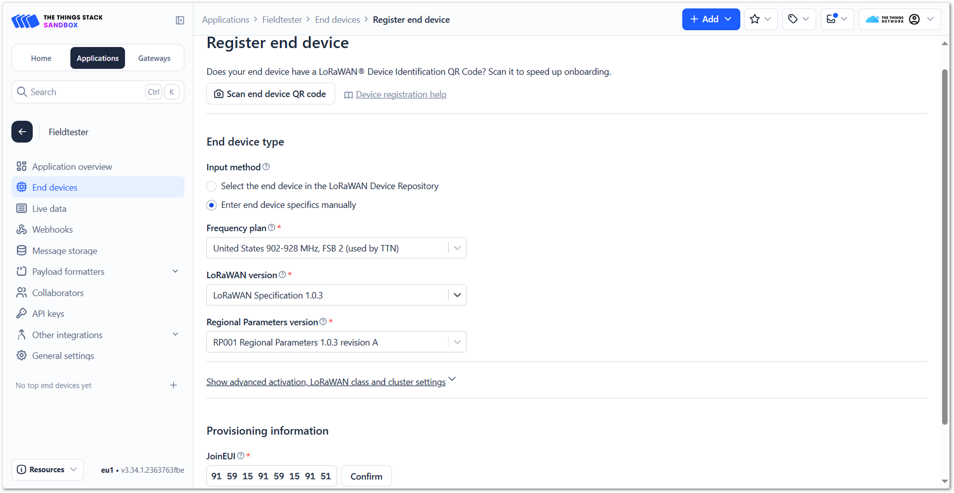 Figure 1: The Things Network JoinEUI and Parameters
- After confirming the JoinEUI, you can proceed to add the other OTAA parameters: DevEUI and AppKey.
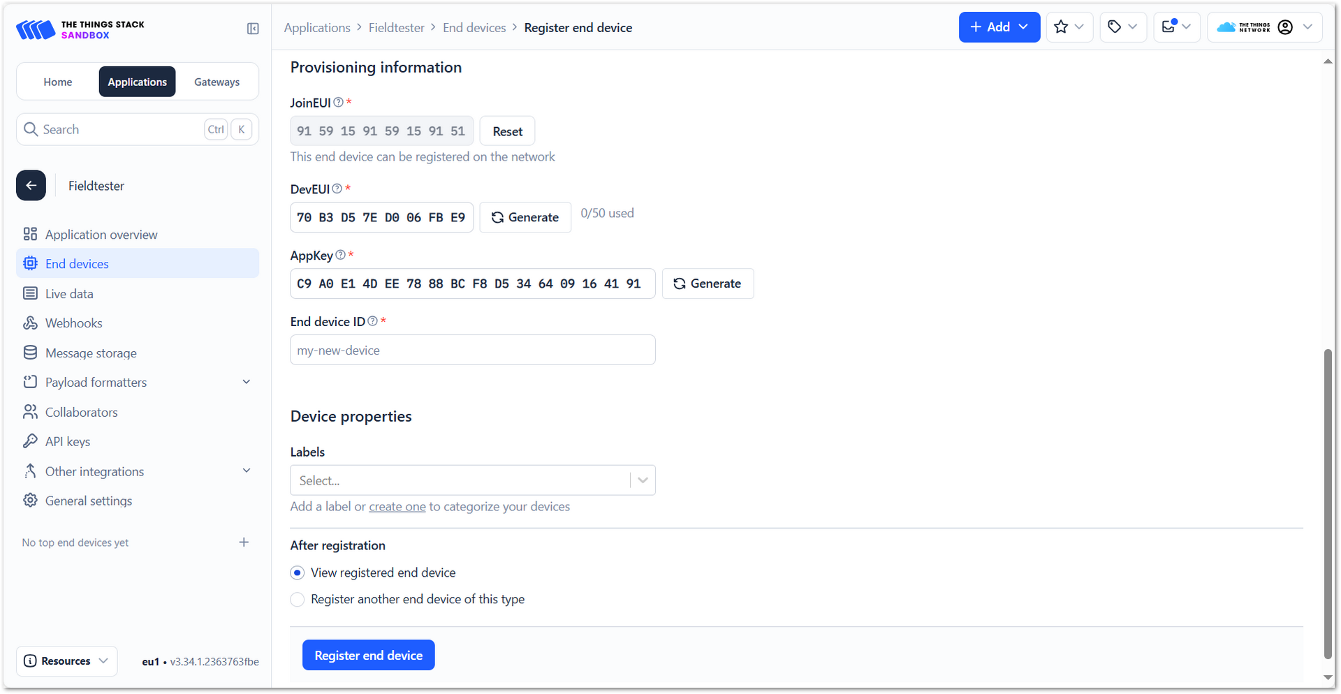 Figure 1: The Things Network DevEUI and AppKey
- Click Register end device.
Once registered, the Field Tester Pad will begin sending periodic uplinks to the TTN LNS.
Now, the device is operating in LinkCheck Mode, as the Field Test Data Processor Extension has not yet been configured. In this mode, the device only displays downlink signal quality metrics.
Figure 1: LinkCheck ModeNext, install and configure the Field Test Data Processor Extension to enable uplink metric reporting .
After the configuration is complete, the device will operate in Field Tester Mode and display both uplink and downlink signal metrics.
Figure 1: Field Tester ModeChirpStack v3
Connect the Gateway to ChirpStack v3
This section explains how to connect and configure a RAK gateway with ChirpStack v3. ChirpStack supports multiple connection methods such as UDP Packet Forwarder, Basics™ Station (LNS), and MQTT (JSON/Protobuf). The specific method you choose depends on your deployment requirements.
To complete the setup, refer to the corresponding official tutorials:
- Registering a RAK Gateway in ChirpStack v3
- Connect RAK Gateways to ChirpStack v3 via UDP Packet Forwarder
- Connect RAK Gateways to ChirpStack v3 Using Basics™ Station (LNS)
- Connect RAK Gateways to ChirpStack v3 via MQTT (Protobuf)
- Connect RAK Gateways to ChirpStack v3 via MQTT (JSON)
Make sure the frequency band configured on the gateway matches the LoRaWAN Band setting of your Field Tester Pad.
Register the Field Tester Pad
- Log in to your ChirpStack account and on the main dashboard page click Device-profiles.
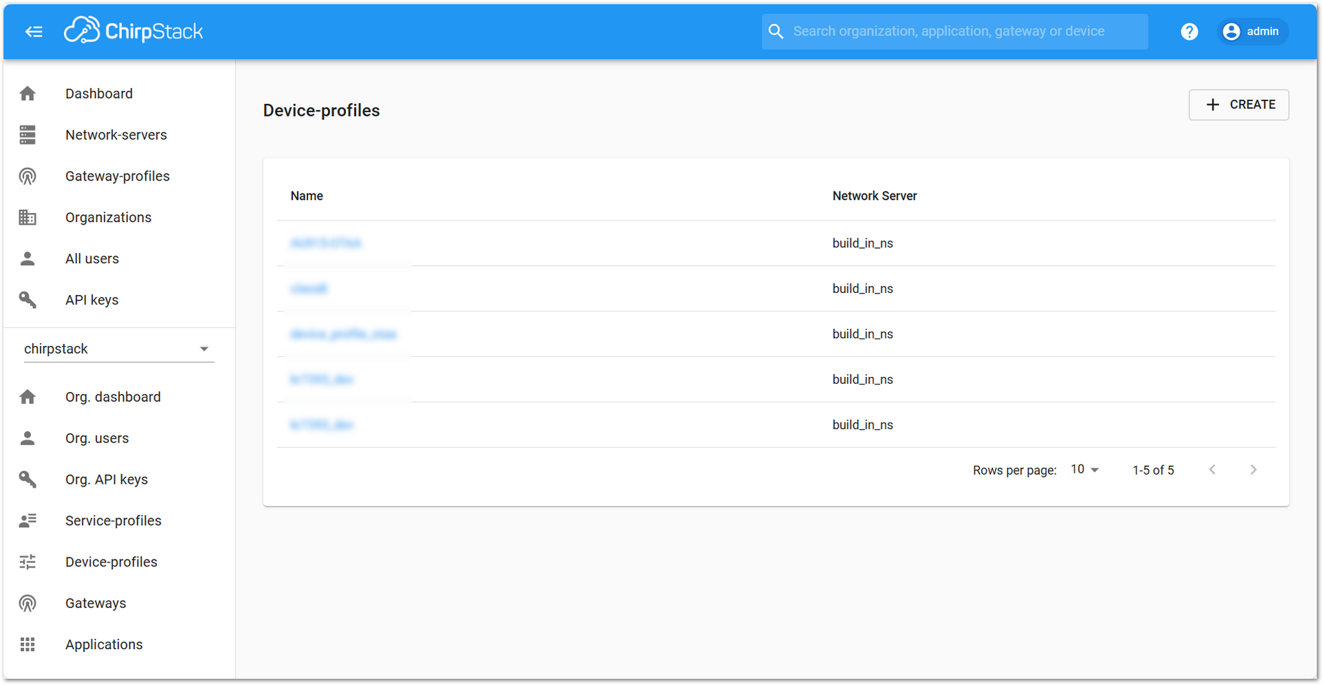 Figure 1: Device profile
- Click + CREATE and fill in the following parameters:
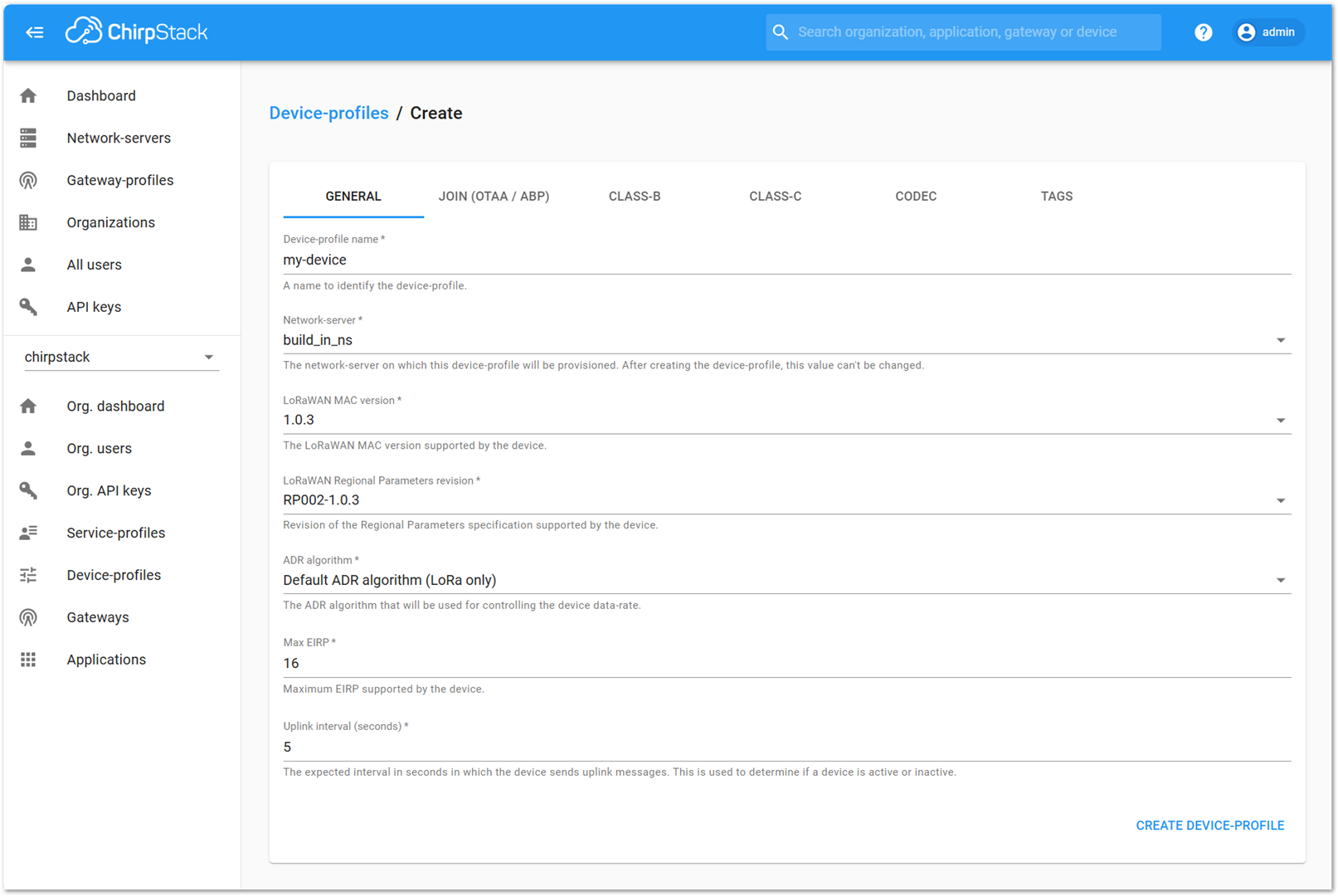 Figure 1: Add Device profile information
- Device-profile name: Provide a descriptive name
- Network-server: build_in_ns
- LoRaWAN MAC version: Select the appropriate version supported by your device
- LoRaWAN Regional Parameters revision: Choose the revision that matches your region
- ADR algorithm: Select Default ADR algorithm (LoRa only)
- Max EIRP: Enter the maximum EIRP supported by the device
- Uplink interval (seconds): Set the desired uplink interval (e.g., 300 seconds or 5 minutes)
- Go to the Join (OTAA / ABP) tab. Check the option: Device supports OTAA.
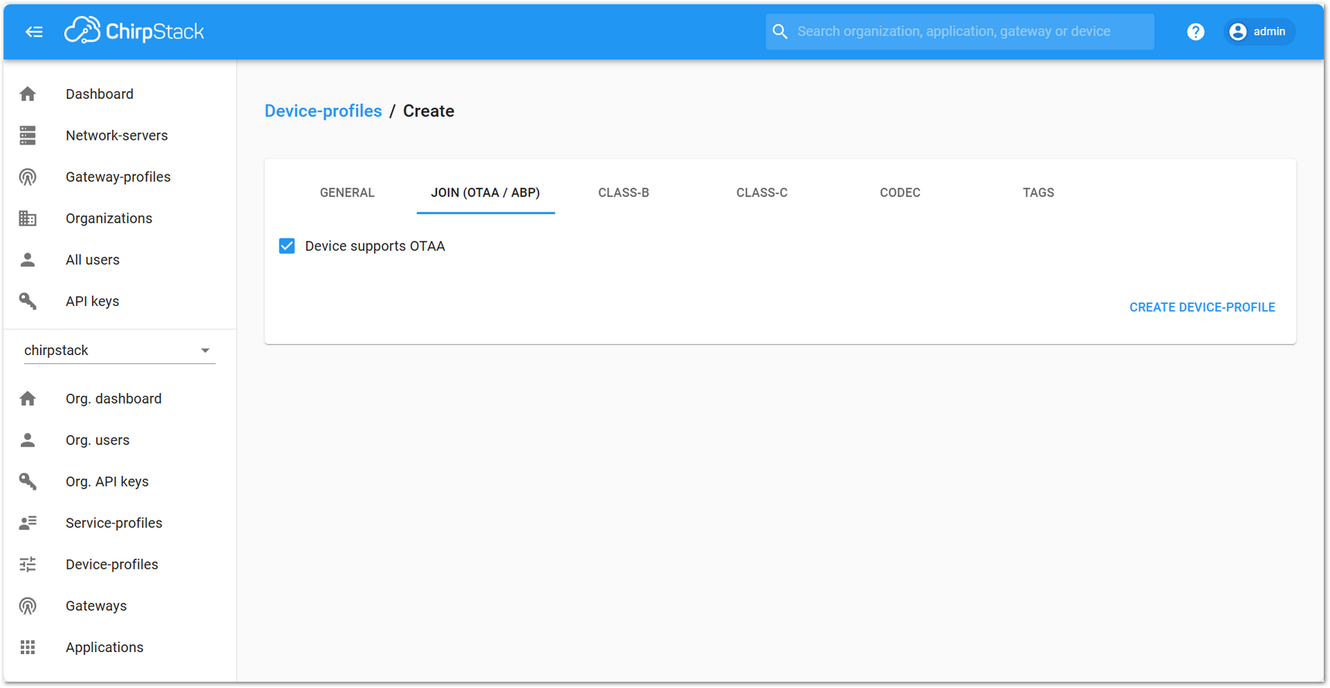 Figure 1: Check Device supports OTAA
- Click CREATE DEVICE PROFILE.
- In the left sidebar, go to Applications.
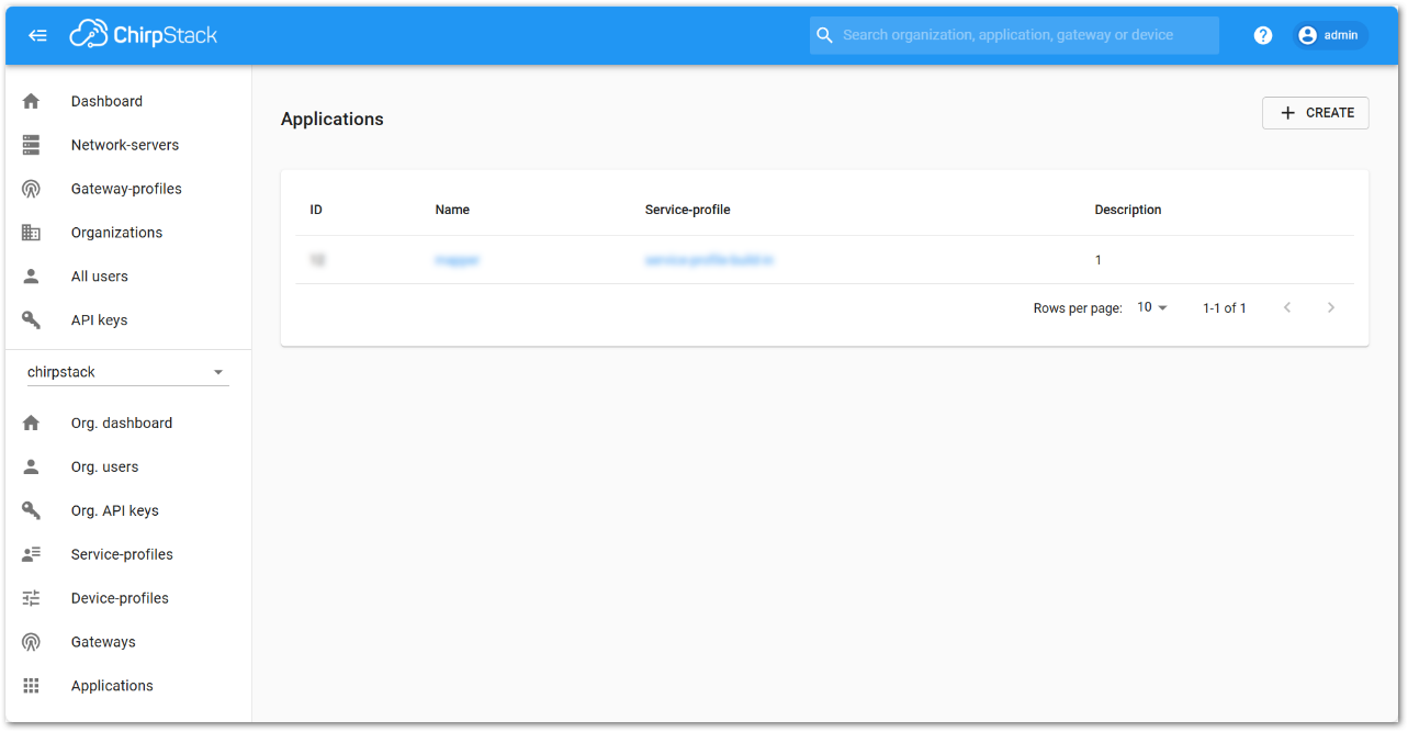 Figure 1: ChirpStack Application
- Click + CREATE.
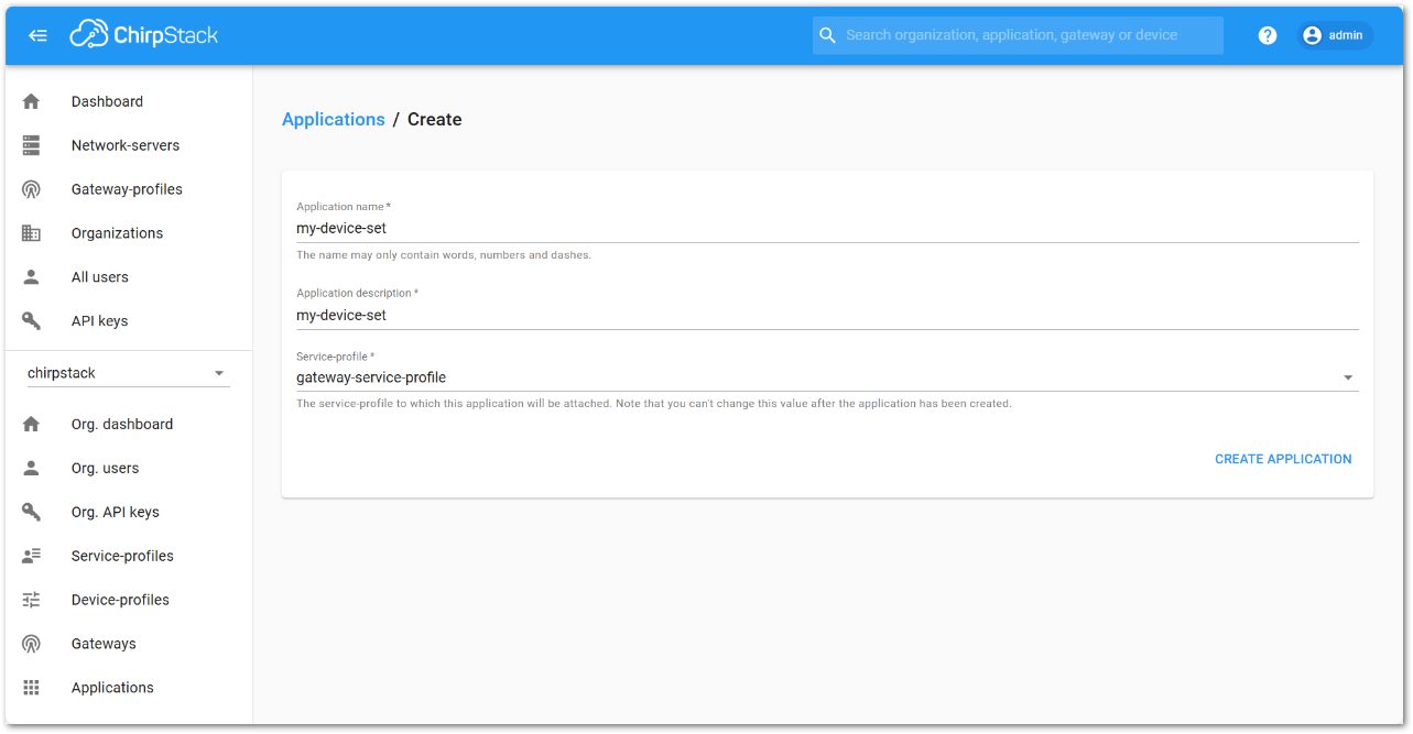 Figure 1: Add Application information
- Fill in the application parameters, then click CREATE APPLICATION.
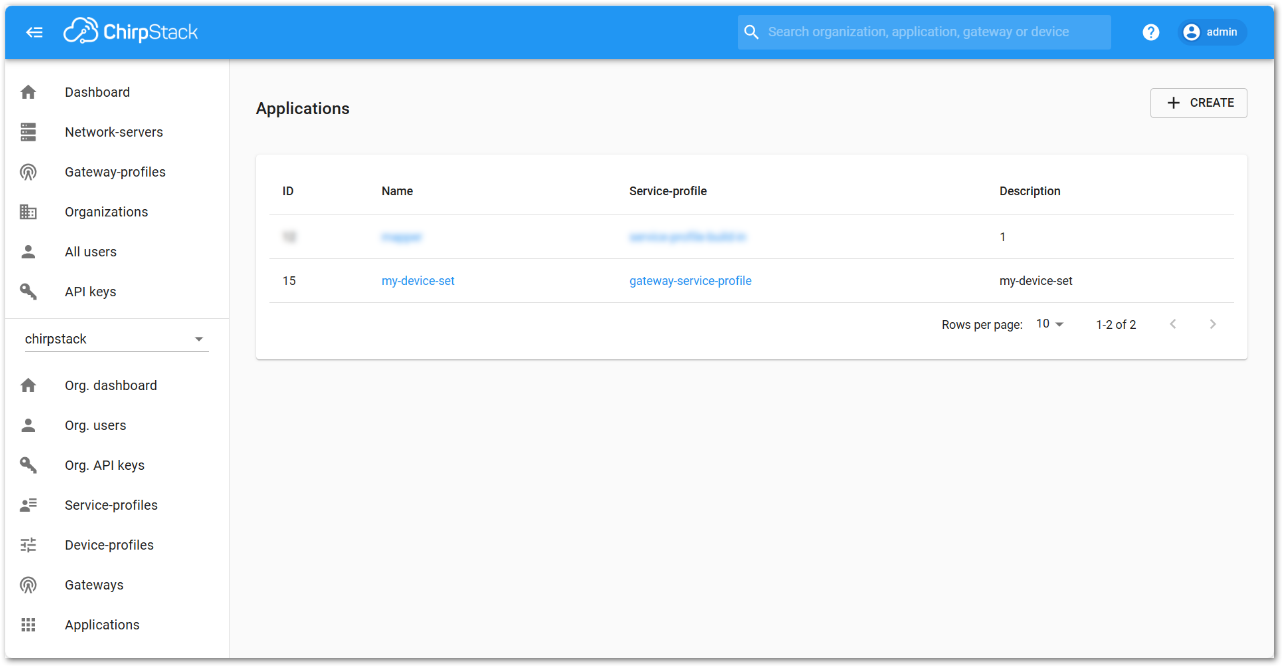 Figure 1: Fill in the application parameters
- Click the name of the application you just created.
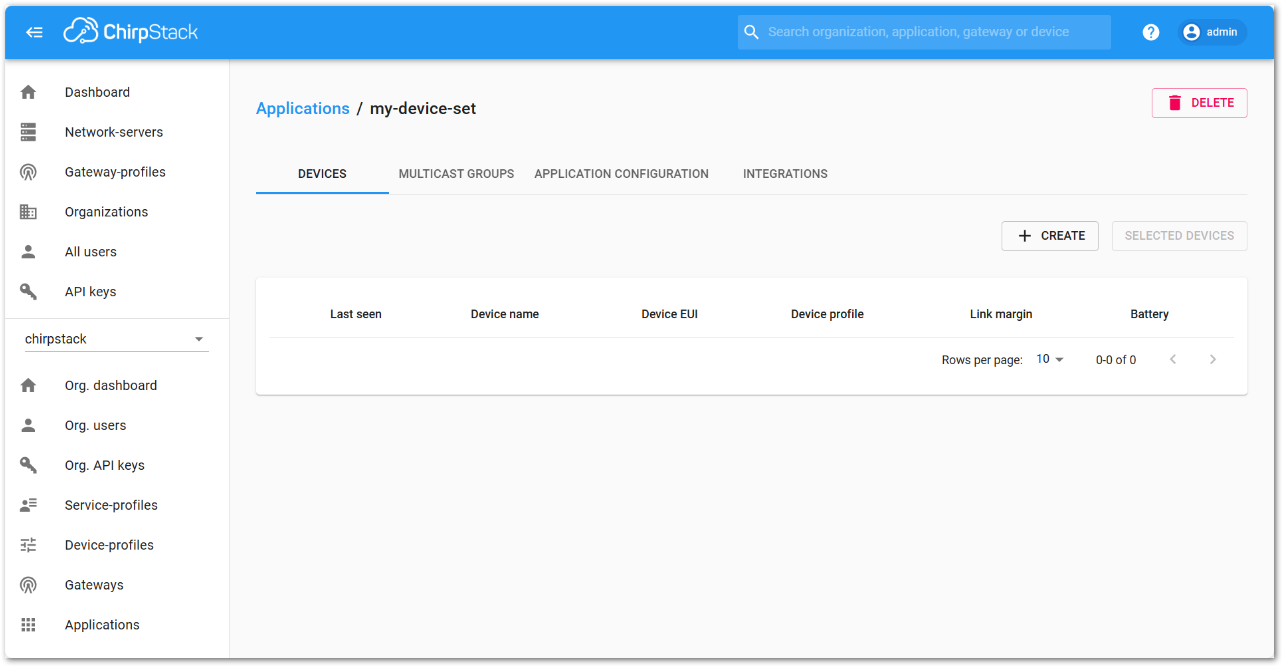 Figure 1: Click the name of the application
- Click + CREATE to register a new device, and fill in the device parameters:
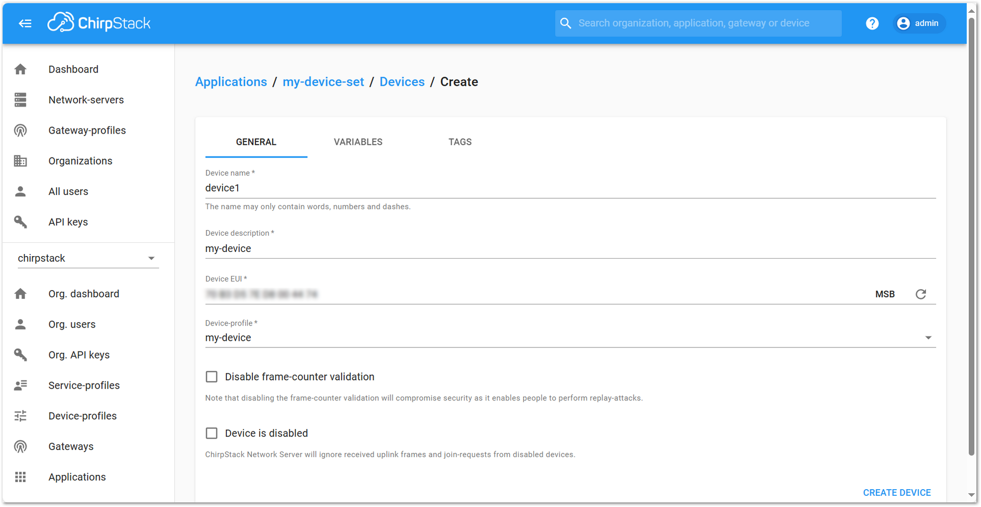 Figure 1: Register a new device
- Device name: A unique name for the device
- Device description: A short description
- Device EUI: Must match the EUI of your Field Tester Pad
- Device-profile: Select the device profile you created earlier
- After saving by clicking CREATE, go to the KEYS (OTAA) tab.
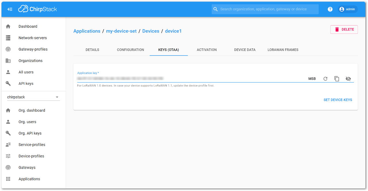 Figure 1: ChirpStack OTAA key
- Enter the Application Key associated with your Field Tester Pad device, then click SET DEVICE KEYS.
Once registered, the Field Tester Pad will begin sending periodic uplinks to the ChirpStack v3 LNS.
Now, the device is operating in LinkCheck Mode, as the Field Test Data Processor Extension has not yet been configured. In this mode, the device only displays downlink signal quality metrics.
Figure 1: LinkCheck ModeNext, install and configure the Field Test Data Processor Extension to enable uplink metric reporting .
After the configuration is complete, the device will operate in Field Tester Mode and display both uplink and downlink signal metrics.
Figure 1: Field Tester ModeChirpStack v4
Connect the Gateway to ChirpStack v4
This section explains how to connect and configure a RAK gateway with ChirpStack v4. ChirpStack supports multiple connection methods, including UDP Packet Forwarder, MQTT, and Basics™ Station (LNS). The method you choose depends on your gateway model and deployment requirements.
To complete the setup, refer to the corresponding official tutorials:
- Registering a RAK Gateway in ChirpStack v4
- Connect RAK Gateways to ChirpStack v4 via UDP Packet Forwarder
- Connect RAK Gateways to ChirpStack v4 via MQTT
- Connect RAK Gateways to ChirpStack v4 Using Basics™ Station (LNS)
Make sure the frequency band configured on the gateway matches the LoRaWAN Band setting of your Field Tester Pad.
Register the Field Tester Pad
- Log in to your ChirpStack account and on the main dashboard page click Applications.
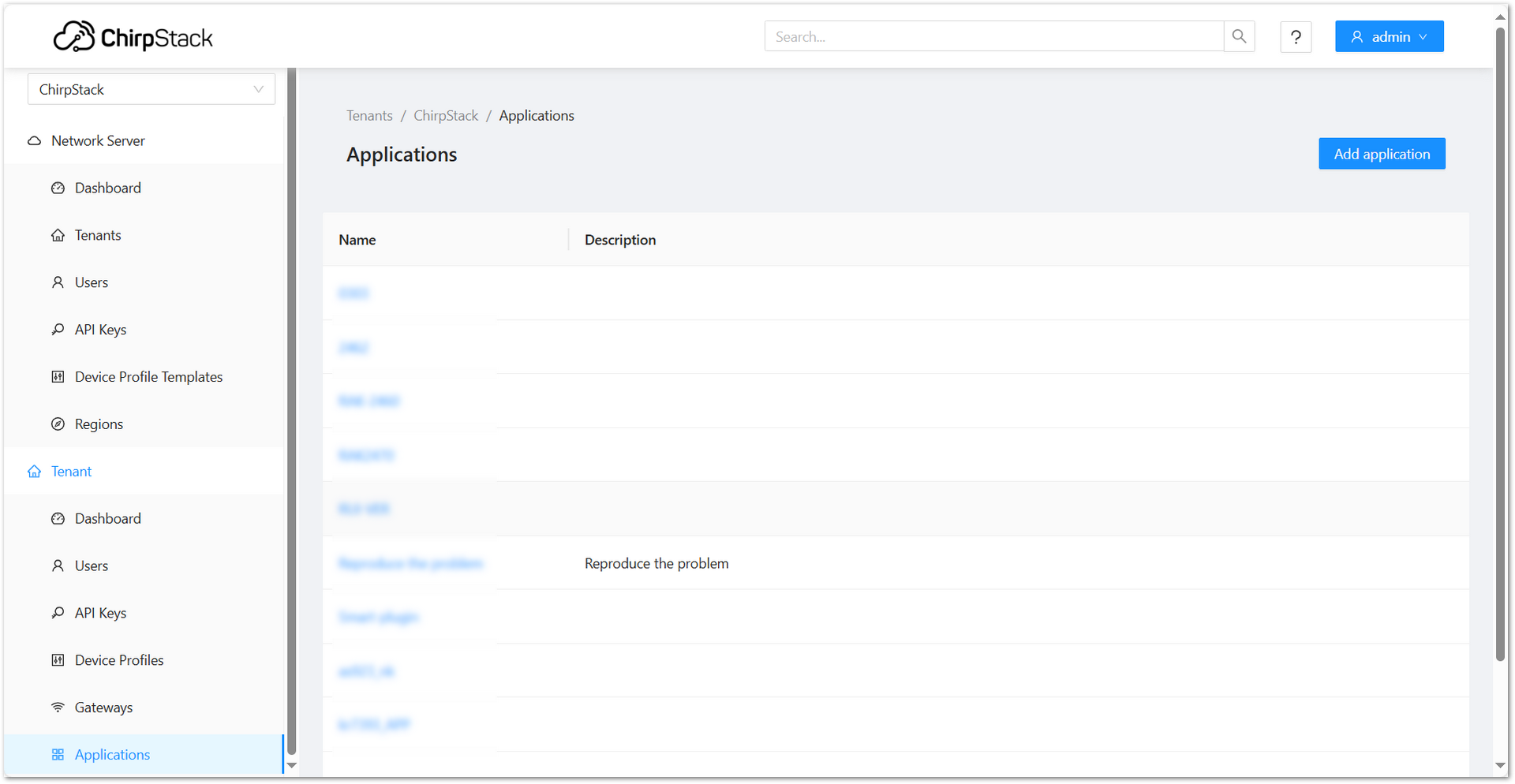 Figure 1: ChirpStack Application Dashboard
- Click Add application and fill in the required fields:
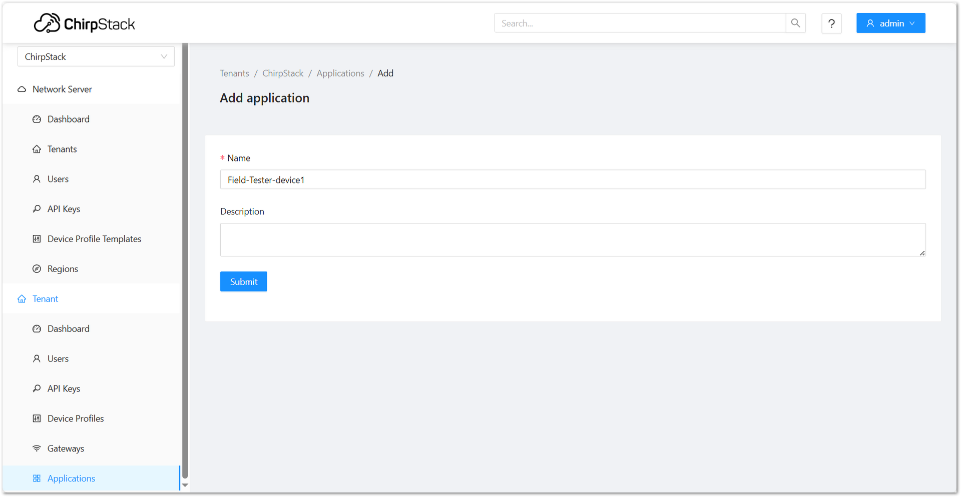 Figure 1: ChirpStack Add Application
-
Click Submit to create the application.
-
Go to Device Profiles and click Add device profile.
 Figure 1: ChirpStack Add Device Profile
- Configure the profile to match your device's specifications:
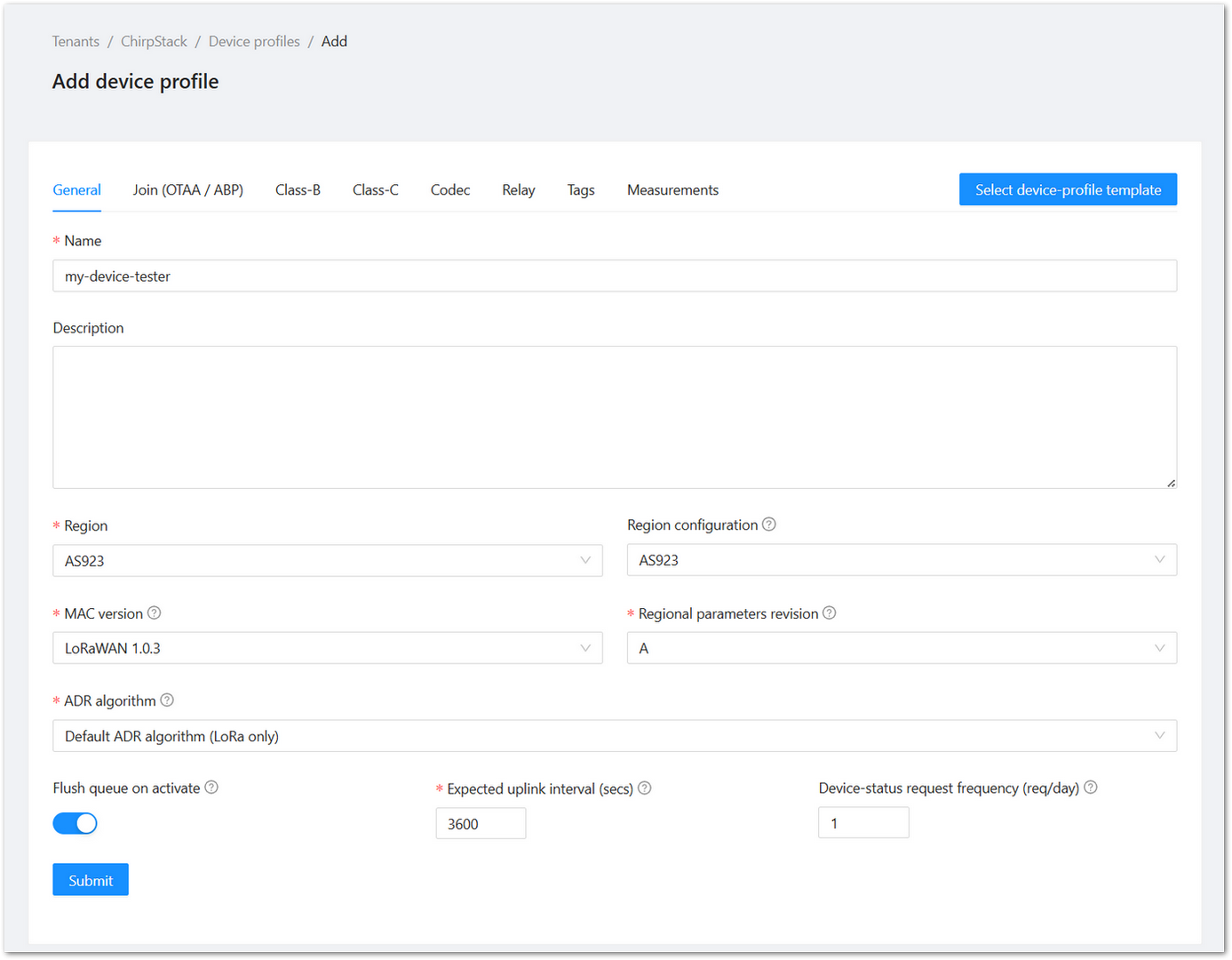 Figure 1: ChirpStack Match Device Specifications
- In the device profile configuration, go to the Join (OTAA / ABP) tab.
- Enable the Device supports OTAA option and click Submit to save the device profile.
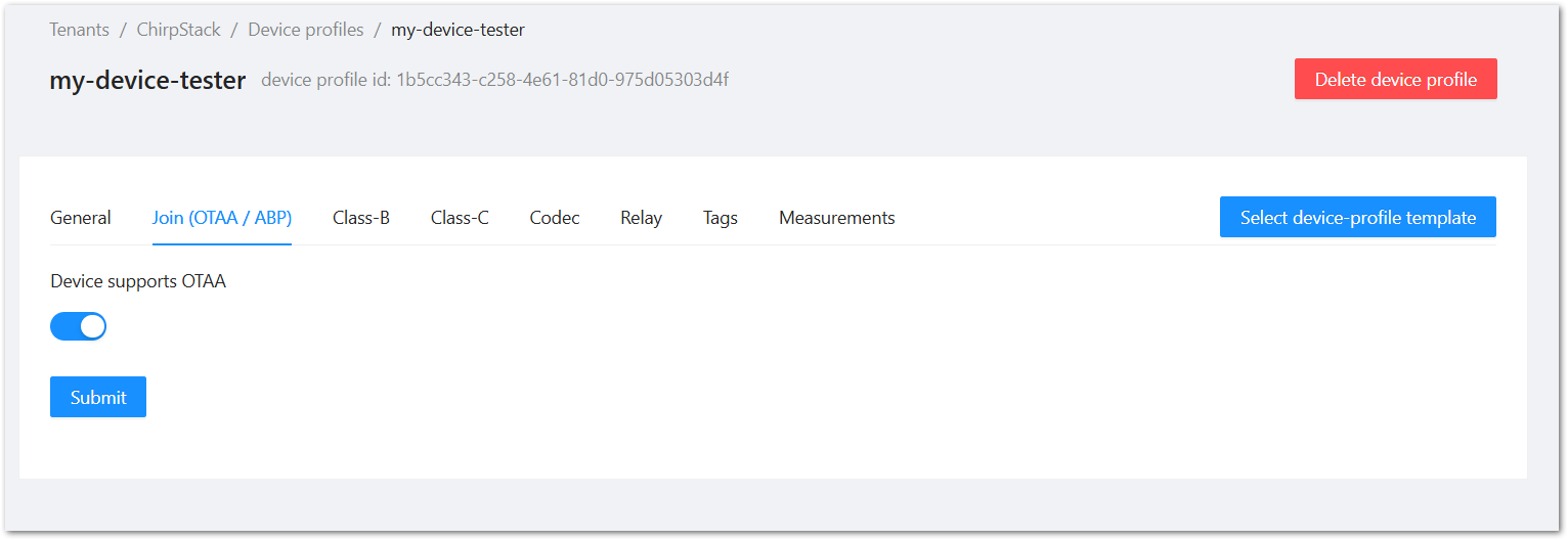 Figure 1: ChirpStack Enable Support OTAA
- Navigate to the Applications > your application and click Add device.
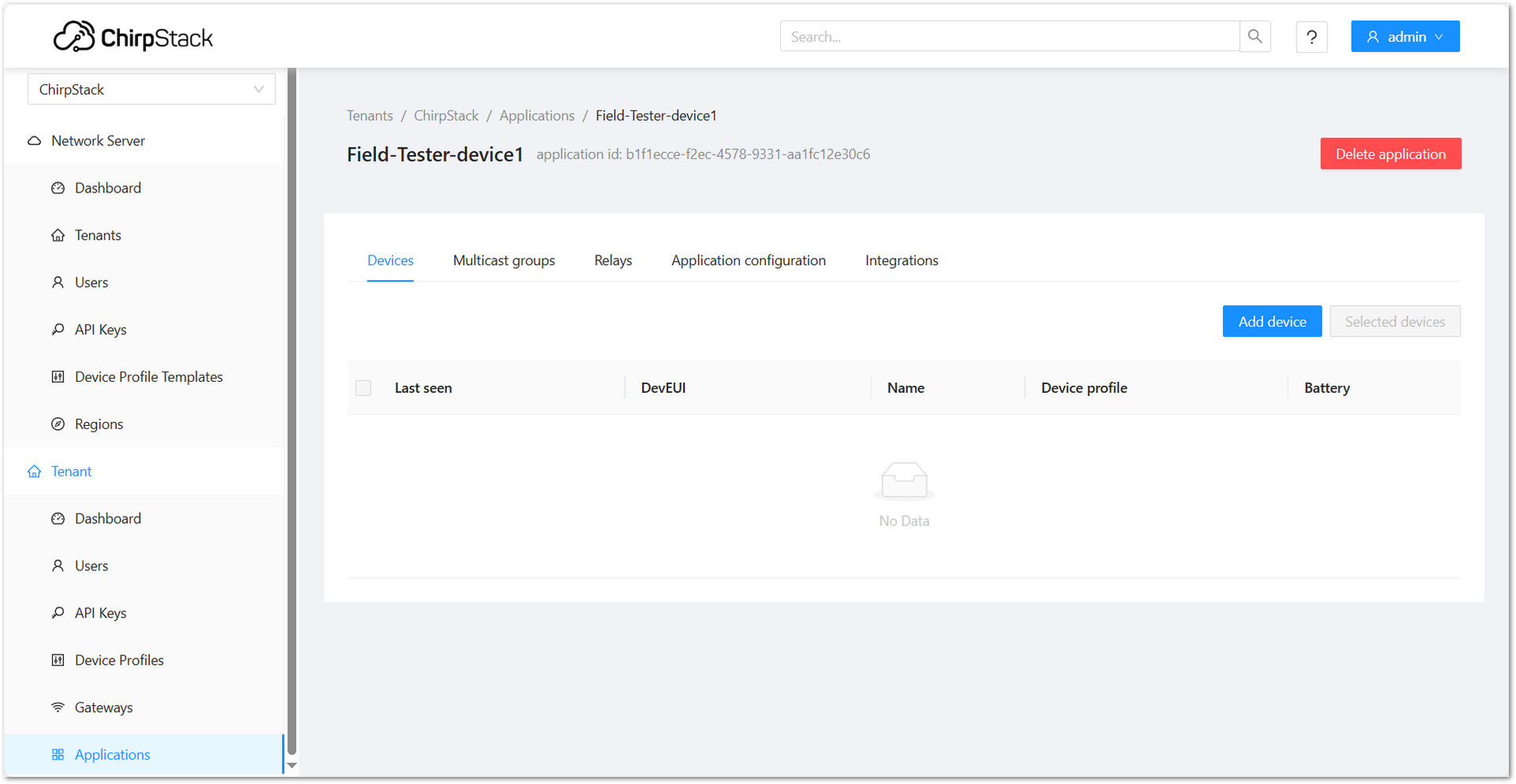 Figure 1: ChirpStack Add Device on Applications
- On the Add Device page, you must enter the device details, including Name, Description, Device EUI, Join EUI, and Device Profile. After entering all required information, click Submit to complete the process.
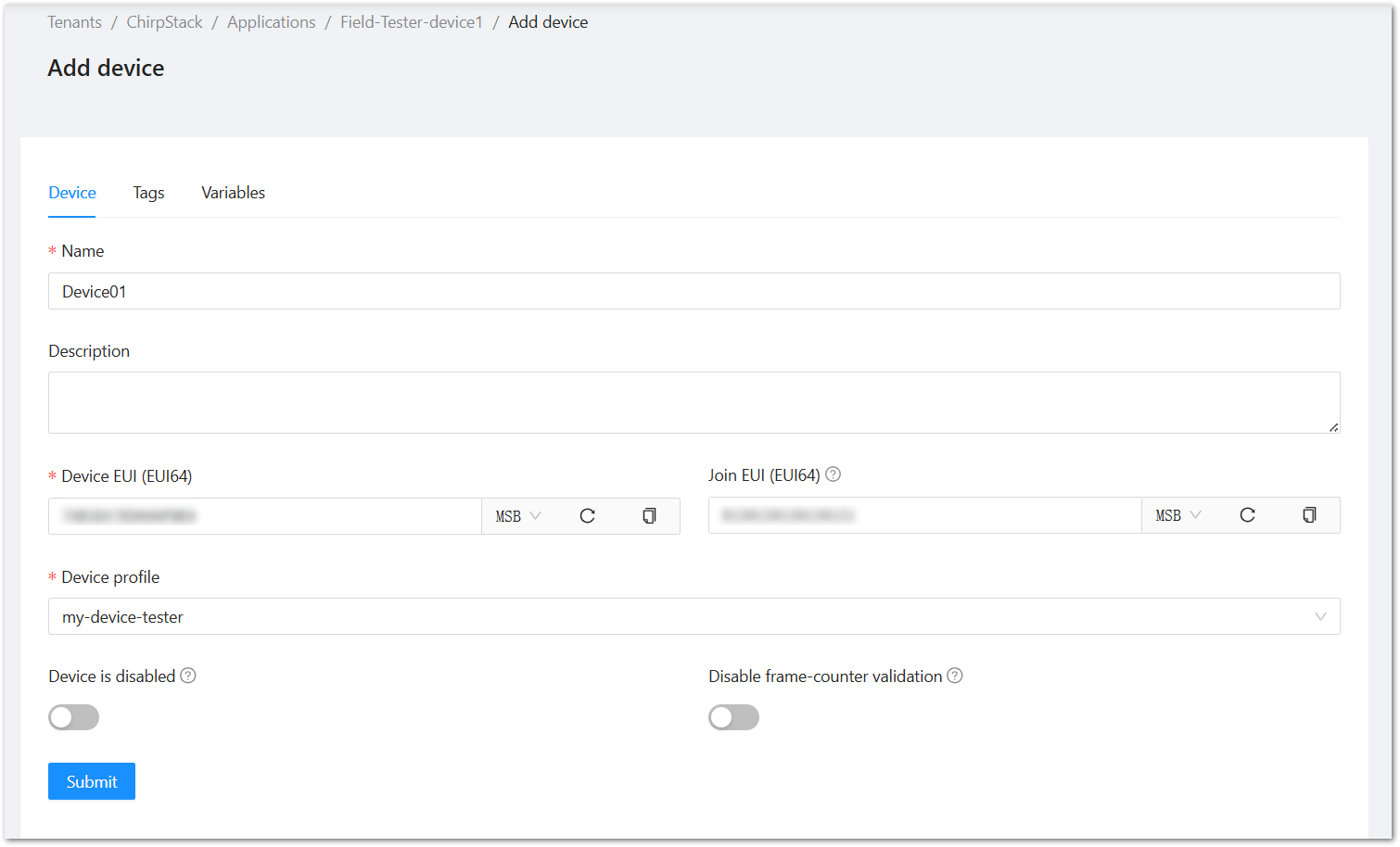 Figure 1: ChirpStack Fill Device Information
- The next step is to provide the Application Key. After entering the Application Key, click Submit to proceed.
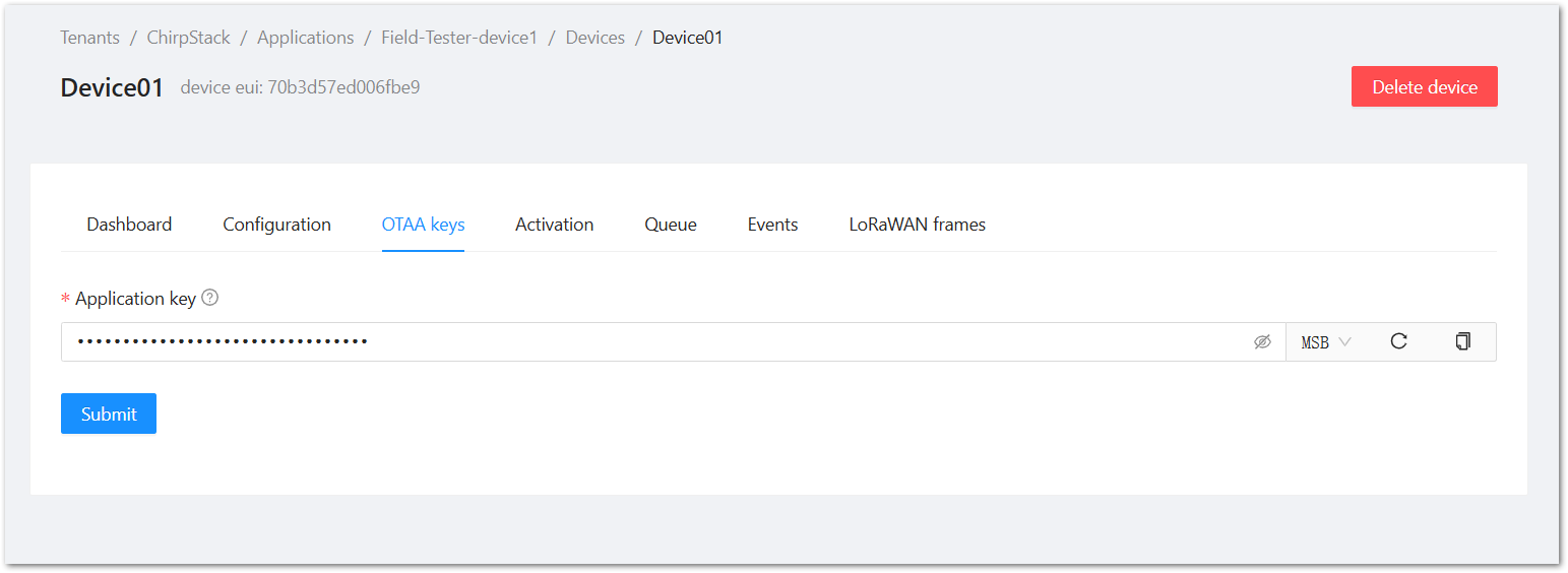 Figure 1: ChirpStack Add Application Key
Once registered, the Field Tester Pad will begin sending periodic uplinks to the ChirpStack v4 LNS.
Now, the device is operating in LinkCheck Mode, as the Field Test Data Processor Extension has not yet been configured. In this mode, the device only displays downlink signal quality metrics.
Figure 1: LinkCheck ModeNext, install and configure the Field Test Data Processor Extension to enable uplink metric reporting .
After the configuration is complete, the device will operate in Field Tester Mode and display both uplink and downlink signal metrics.
Figure 1: Field Tester ModeAWS IoT Core for LoRaWAN
Connect the Gateway to AWS IoT Core for LoRaWAN
This section explains how to connect and configure a RAK gateway with AWS IoT Core for LoRaWAN. AWS supports LoRaWAN connections through Basics™ Station (LNS) and Basics™ Station (CUPS). The method you choose depends on your gateway deployment strategy and certificate management requirements.
To complete the setup, refer to the corresponding official tutorials:
- Connect RAK Gateways to AWS IoT Core Using Basics™ Station (LNS)
- Connect RAK Gateways to AWS IoT Core Using Basics™ Station (CUPS)
Make sure the frequency band configured on the gateway matches the LoRaWAN Band setting of your Field Tester Pad.
Register the Field Tester Pad
Create a destination role for AWS IoT Core for LoRaWAN
To allow AWS IoT Core for LoRaWAN to forward device data to AWS services (via Destinations), you must assign an IAM role and policy that authorizes the service to publish messages on your behalf. If you've already created this IAM role during gateway setup, there's no need to create it again. Otherwise, follow the official AWS instructions below to set it up: Create a destination role for AWS IoT Core for LoRaWAN
Verify Profiles
- Navigate to the AWS IoT console.
- In the navigation pane, go to LPWAN Devices > Profiles.
- Under Device Profiles, review the pre-defined options.
- If none fit your device or region, click Add device profile and configure custom parameters.
- Example: For AS923-1, set parameters accordingly.
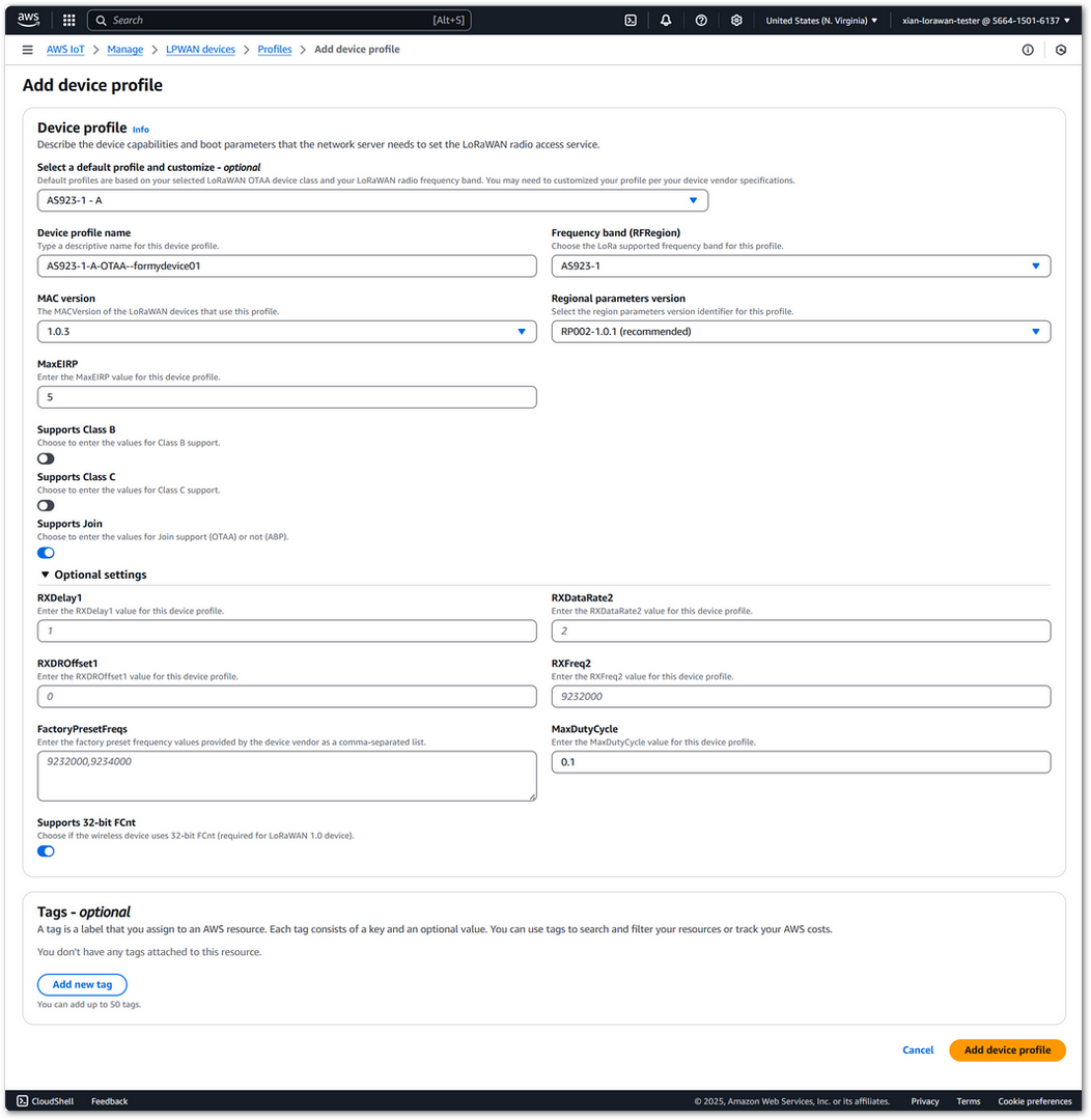 Figure 1: AWS Add Device Profile
- Click Add device profile to save.
- In the Service Profiles section, click Add service profile and configure service parameters (default values are generally acceptable).
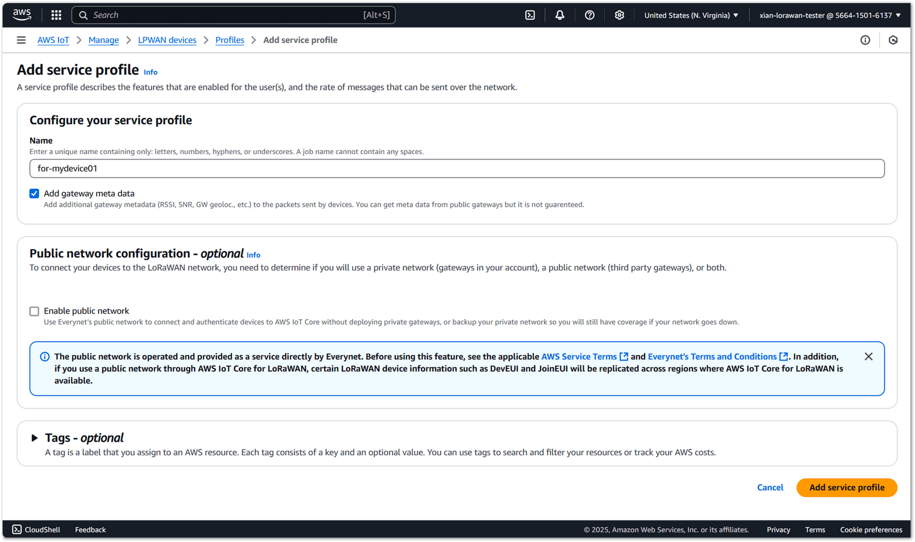 Figure 1: AWS Add Service Profile
- Once you have created appropriate Device and Service Profiles, proceed to set up a destination for device traffic.
Set Up a Destination for Device Traffic
To use the Field Tester Extension with AWS IoT Core for LoRaWAN, you must associate your device with a Destination. This defines where your uplink data will be sent.
- Navigate to the AWS IoT console.
- In the navigation pane, choose LPWAN devices, and then Destinations.
- Choose Add Destination.
- Fill in the Destination details:
- For the Destination name, enter ProcessFieldTesterUplink. The name can be customized.
- Destination description (optional): Provide a helpful description.
- For the Destination name, enter ProcessFieldTesterUplink. The name can be customized.
- Select Publish to AWS IoT Core message broker. This allows the uplink messages to be published to an MQTT topic for other applications or services to consume.
- Enter a topic such as RecvFieldTesterUplink.
- In the Permissions section, choose Select an existing service role and select the IAM role you had created earlier, from the dropdown.
- Choose Add Destination. You will see a message Destination added, indicating the destination has been successfully added.
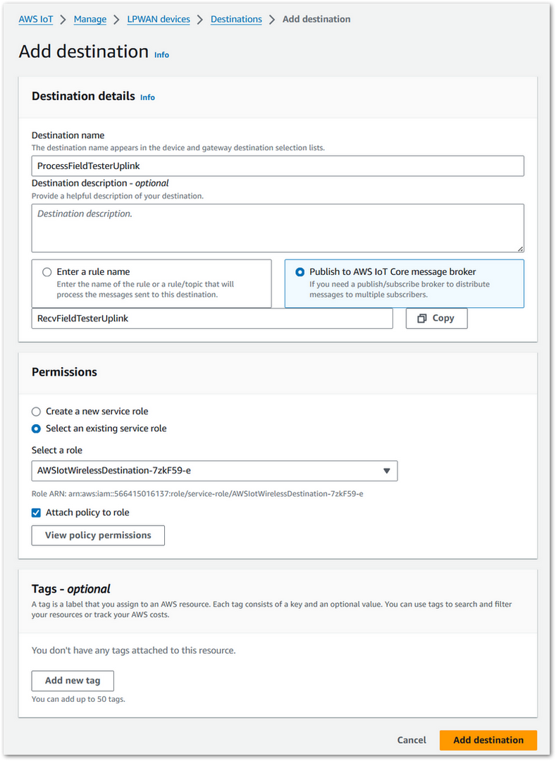 Figure 1: AWS Add Destination
Register Device
- In the navigation pane, go to LPWAN Devices > Devices.
- Click Add wireless device.
- On the Add Device page:
- Select the LoRaWAN specification version in the dropdown under Wireless device specification.
- Enter the DevEUI.
- Fill in the AppEUI/JoinEUI and AppKey as per your OTAA settings.
- Provide a wireless Device name.
- Under Profiles, select the Device Profile and Service Profile you created earlier.
- Under Destination, choose the one previously created.
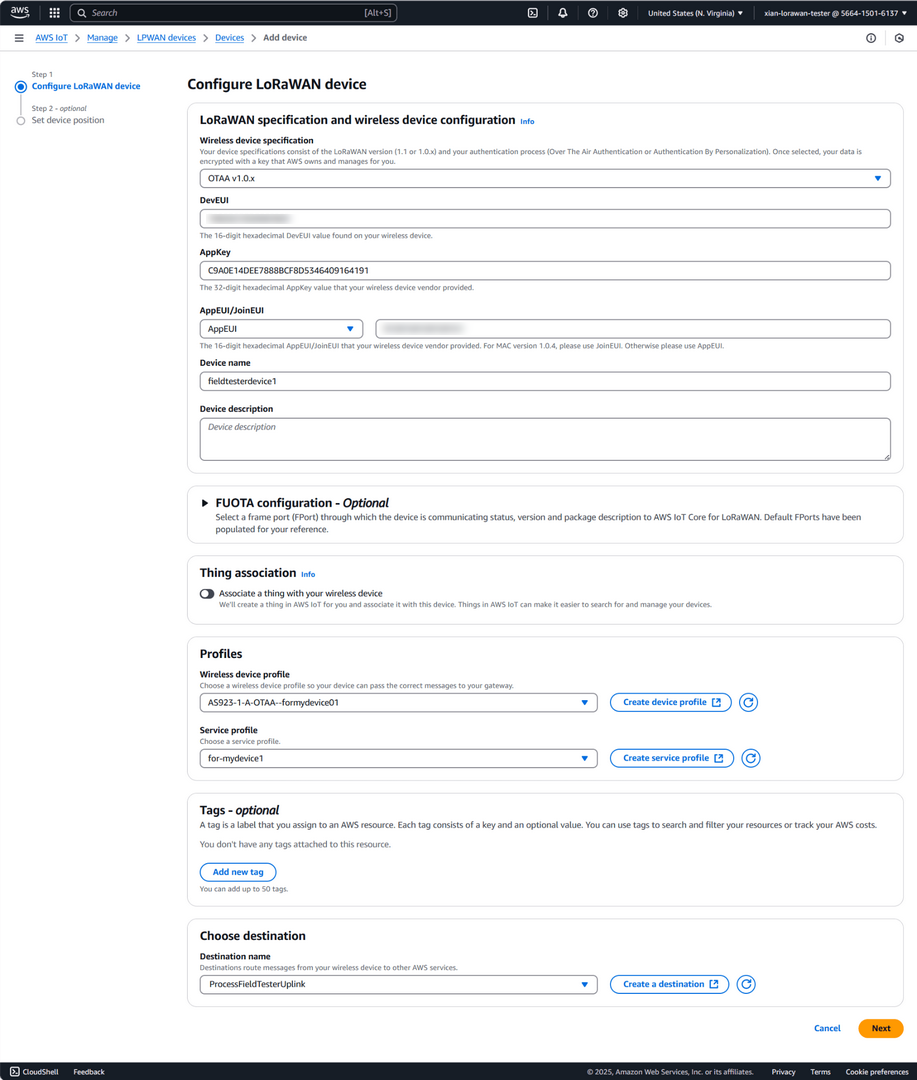 Figure 1: AWS Configure LoRaWAN Device
- Click Next, then Add device to complete registration.
Once registered, the Field Tester Pad will begin sending periodic uplinks to the AWS IoT Core.
Now, the device is operating in LinkCheck Mode, as the Field Test Data Processor Extension has not yet been configured. In this mode, the device only displays downlink signal quality metrics.
Figure 1: LinkCheck ModeNext, install and configure the Field Test Data Processor Extension to enable uplink metric reporting .
After the configuration is complete, the device will operate in Field Tester Mode and display both uplink and downlink signal metrics.
Figure 1: Field Tester ModeThe Things Industries (TTI)
Connect the Gateway to TTI
This section explains how to connect and configure a RAK gateway with The Things Industries (TTI). Since TTI and TTN share the same core platform (The Things Stack), the gateway registration process is identical to TTN. You may follow the TTN registration guide for creating the gateway entry.
- When configuring the gateway to connect to TTI, make sure you enter the correct TTI server URL. Unlike TTN, which uses public community clusters, TTI uses private cluster URLs provided specifically for your organization or deployment.
- Make sure the frequency band configured on the gateway matches the LoRaWAN Band setting of your Field Tester Pad.
Register Field Tester Pad on TTI
- Log in to your organization’s TTI Console.
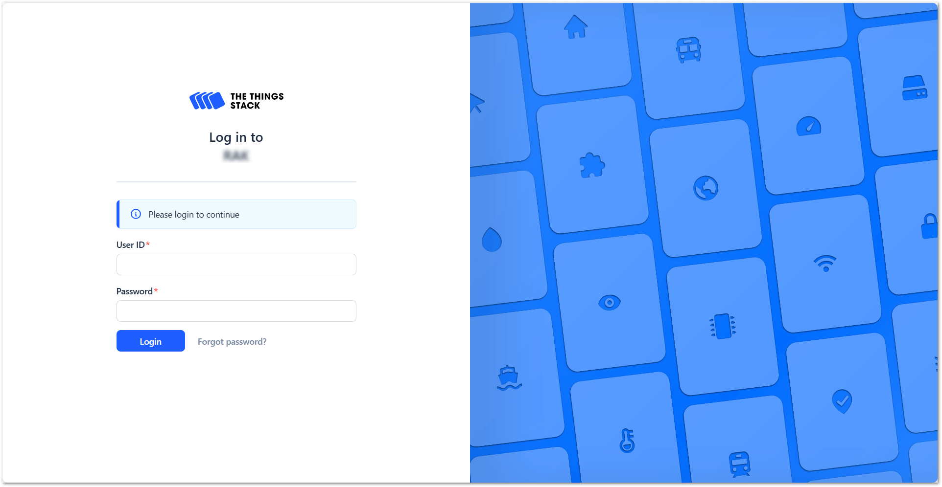 Figure 1: The Things Stack Login page
- To create an application, go to Applications > + Add application.
Figure 1: Create an application- Add Application ID, Application name and Description then click Create application.
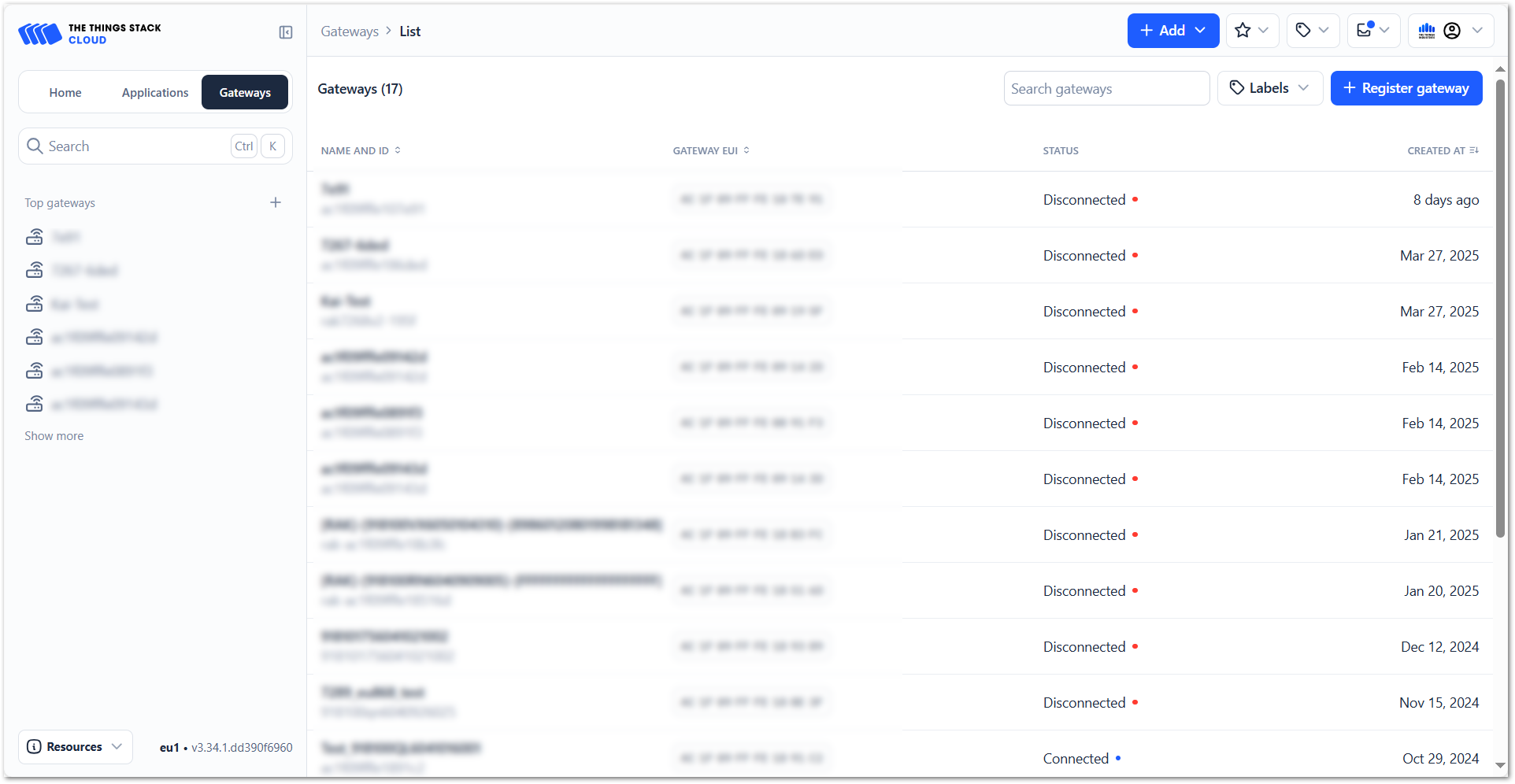 Figure 1: Register gateway
- Click Register end device within your newly created application.
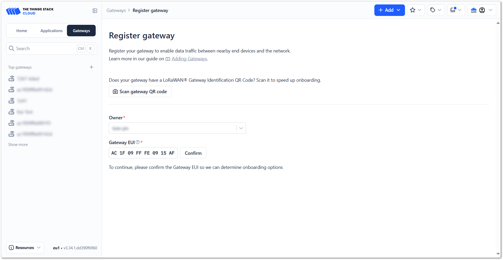 Figure 1: Register end device
- Choose Enter end device specifics manually. This will allow you to add the Frequency plan, LoRaWAN version, Regional Parameters version and JoinEUI. The values of these parameters depend on the hardware you use. If your device has a preconfigured JoinEUI, you must use it. Click Confirm after putting all the details.
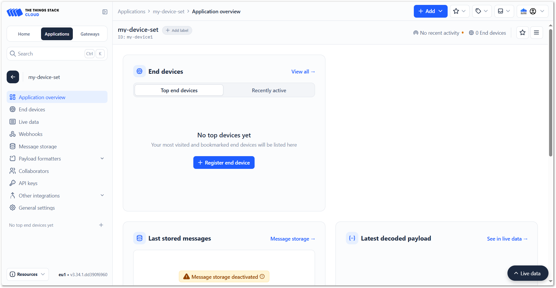 Figure 1: Enter end device specifics
- After confirming the JoinEUI, you can proceed on adding other OTAA parameters – DevEUI and AppKey.
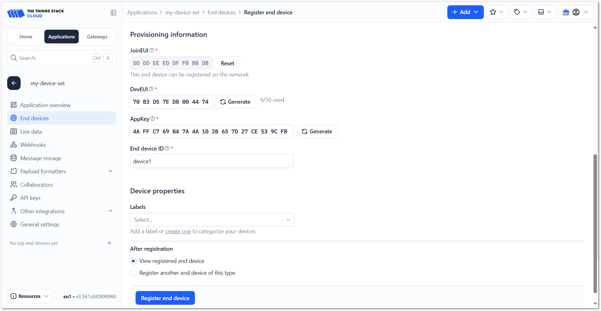 Figure 1: Add OTAA parameters
- Click Register end device.
Once registered, the Field Tester Pad will begin sending periodic uplinks to the TTI LNS.
Now, the device is operating in LinkCheck Mode, as the Field Test Data Processor Extension has not yet been configured. In this mode, the device only displays downlink signal quality metrics.
Figure 1: LinkCheck ModeNext, install and configure the Field Test Data Processor Extension to enable uplink metric reporting .
After the configuration is complete, the device will operate in Field Tester Mode and display both uplink and downlink signal metrics.
Figure 1: Field Tester ModeConfigure the Field Test Data Processor Extension
The Field Test Data Processor Extension enables the Field Tester Pad to visualize uplink and downlink signal metrics on the gateway dashboard.
This section provides the general procedure to install the extension and the platform-specific configuration links for each LoRaWAN Network Server (LNS).
Download and Install the Extension
First, download the Field Test Data Processor Extension. For detailed instructions on installing an extension on WisGateOS 2, refer to: How to Add an Extension.
Configure the Extension
After installation, you must configure the extension according to the LNS platform used at your site.
Select the appropriate platform below:
- Built-in Network Server (WisGateOS 2)
Extension Configuration for Built-in Network Server - The Things Network (TTN)
Extension Configuration for The Things Network - ChirpStack v3
Extension Configuration for ChirpStack v3 - ChirpStack v4
Extension Configuration for ChirpStack v4 - AWS IoT Core for LoRaWAN
Extension Configuration for AWS IoT Core for LoRaWAN - The Things Industries (TTI)
Extension Configuration for The Things Industries