RAK6421 WisBlock Hat for Raspberry Pi Datasheet
Overview
Description
The RAK6421 WisBlock Pi Hat is a powerful Raspberry Pi HAT that enables direct integration of WisBlock modules with any Raspberry Pi board (Pi 4, Pi 5, or Pi Zero 2W). Whether you're building a Meshtastic router, a sensor gateway, or a LoRa test platform, the RAK6421 streamlines development with its modular, plug‑and‑play support for LoRa radios, GPS, environmental sensors, and more. The RAK6421 WisBlock Pi HAT also includes an independent EEPROM used as the HAT+ ID EEPROM.
Features
- Standard 40-pin Raspberry Pi connector
- Two (2) WisBlock IO slots
- Four (4) WisBlock Sensor slots
- Supports LoRa radios, I2C sensors, GPS, I2S audio
- Built-in I2C ADC for analog input (e.g., temperature, light)
- Powers modules via 3.3 V and VBAT from Pi's 5 V rail
- Compatible with RAK13300 an.2d RAK13302 LoRa radios
- Add-on options: Raspberry Pi, enclosure, and sensor bundles
- On-board EEPROM connected to
ID_SDandID_SCsignals
Specifications
Hardware
The RAK6421 WisBlock Hat for Raspberry Pi has 4 sensor slots (A, B, C, and D) and 2 IO slots (1 and 2). Sensor slots A and C can hold a long sensor module (like GPS modules), but if a long sensor module is placed on slot C, slot D will not be accessible.
Block Diagram
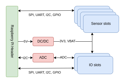 Figure 1: RAK6421 WisBlock Hat for Raspberry Pi Block Diagram
Raspberry Pi Header
The RAK6421 comprises a standard Raspberry Pi header. The 40 pin Header allows the RAK6421 module to be mounted of a Raspberry Pi or compatible device. The pinout follows the standard Raspberry Pi pinout. See image below.
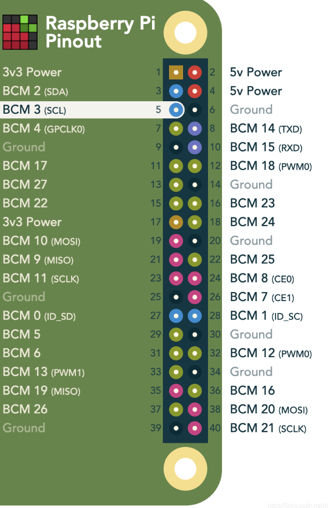 Figure 1: Raspberry Pi pinout
WisBlock Connectors
Signals on IO Slots| Pin Number | Slot 1 | Slot 2 |
|---|---|---|
| 1 | VBAT | VBAT |
| 2 | VBAT | VBAT |
| 3 | GND | GND |
| 4 | GND | GND |
| 5 | 3V3 | 3V3 |
| 6 | 3V3 | 3V3 |
| 7 | NC | NC |
| 8 | NC | NC |
| 9 | 5V | 5V |
| 10 | NC | NC |
| 11 | TXD0 | TXD0 |
| 12 | RXD0 | RXD0 |
| 13 | GPIO27 | GPIO27 |
| 14 | NC | NC |
| 15 | NC | NC |
| 16 | NC | NC |
| 17 | 3V3 | 3V3 |
| 18 | 3V3 | 3V3 |
| 19 | SDA1 | SDA1 |
| 20 | SCL1 | SCL1 |
| 21 | AIN0 | AIN2 |
| 22 | AIN1 | AIN3 |
| 23 | NC | NC |
| 24 | NC | NC |
| 25 | CS0 | CS1 |
| 26 | SCLK | SCLK |
| 27 | MISO | MISO |
| 28 | MOSI | MOSI |
| 29 | GPIO17 | GPIO25 |
| 30 | GPIO12 | GPIO26 |
| 31 | GPIO13 | GPIO23 |
| 32 | GPIO16 | GPIO24 |
| 33 | TXD0 | TXD0 |
| 34 | RXD0 | RXD0 |
| 35 | SDA1 | SDA1 |
| 36 | SCL1 | SCL1 |
| 37 | GPIO19 | GPIO24 |
| 38 | GPIO18 | GPIO22 |
| 39 | GND | GND |
| 40 | GND | GND |
| Pin Number | Slot A | Slot B | Slot C | Slot D |
|---|---|---|---|---|
| 1 | TXD0 | NC | NC | TXD0 |
| 2 | GND | GND | GND | GND |
| 3 | CS0 | CS0 | CS1 | CS1 |
| 4 | SCLK | SCLK | SCLK | SCLK |
| 5 | MISO | MISO | MISO | MISO |
| 6 | MOSI | MOSI | MOSI | MOSI |
| 7 | SCL1 | SCL1 | SCL1 | SCL1 |
| 8 | SDA1 | SDA1 | SDA1 | SDA1 |
| 9 | 3V3 | 3V3 | 3V3 | 3V3 |
| 10 | GPIO12 | GPIO16 | GPIO22 | GPIO24 |
| 11 | 3V3 | 3V3 | 3V3 | 3V3 |
| 12 | GPIO6 | GPIO13 | GPIO21 | GPIO23 |
| 13 | NC | NC | NC | NC |
| 14 | 3V3 | 3V3 | 3V3 | 3V3 |
| 15 | NC | NC | NC | NC |
| 16 | 3V3 | 3V3 | 3V3 | 3V3 |
| 17 | NC | NC | NC | NC |
| 18 | NC | NC | NC | NC |
| 19 | NC | NC | NC | NC |
| 20 | NC | NC | NC | NC |
| 21 | NC | NC | NC | NC |
| 22 | NC | NC | NC | NC |
| 23 | GND | GND | GND | GND |
| 24 | RXD0 | GND | GND | RXD0 |
- VBAT is 4V17 obtained from 5 V power supply in the Raspberry Pi header.
- 3V3 is obtained from 5 V power supply in the Raspberry Pi header.
- NC means Not Connected.
- GPIOXX refers to Broadcom GPIO number, not header pin number.
Analog Input
The RAK6421 includes an SGM58031XMS10G/TR Analog-to-Digital converter (compatible with ADS1115). This is wired by default to listen on I2C address 0x48. Alternative addresses (0x49, 0x4A or 0x4B) can be configured reworking the resistors nearby the ADC chip. See info in the silkscreen. The 4 analog signals (AIN0 to 3) are available on the IO slots and one of them (AIN1) on the J8 header as well. The 4 analog inputs support 0 to 3V3 and can also be configured for differential readings, which might be used with RAK16001.
EEPROM
The RAK6421 includes an onboard EEPROM (CAT24C32 compatible) to comply with Raspberry Pi HAT+ specification. The EEPROM is read-only by default, but can be set into read-write by shortening J10 pins.
This EEPROM is connected to the secondary I2C bus in the Raspberry Pi Hat and it's meant to house metadata and the device tree for the hardware on the board.
If interested, and for a MOQ, we can flash the EEPROM in factory for customized configurations.
Interfaces
J8 Header Pinout
| Pin | Pin Name | Description |
|---|---|---|
| 1 | AIN1 | Analog IN |
| 2 | IO4 | GPIO4 |
| 3 | IO5 | GPIO5 |
| 4 | VBAT | VBAT output (4.17 V) |
J9 Header Pinout
| Pin | Pin Name | Description |
|---|---|---|
| 1 | 3V3 | VOUT (3.3 V) |
| 2 | GND | GND |
| 3 | I2C1_SCL | SCL |
| 4 | I2C1_SDA | SCA |
Operating Conditions
The table below lists the operation voltage and temperature ranges:
| Parameter | Description | Min. | Typ. | Max. |
|---|---|---|---|---|
| 5V | Power supply from Raspberry Pi | 4.9 V | 5.0 V | 5.1 V |
| 3V3 | 3V3 to WisBlock modules | 3.3 V | ||
| VBAT | VBAT to WisBlock modules | 4.17 V | ||
| AIN0 to AIN3 | Analog Input | 3.3 V | ||
| Operating Temperature | Temperature Range | -40° C | +25° C | +85° C |
Schematics
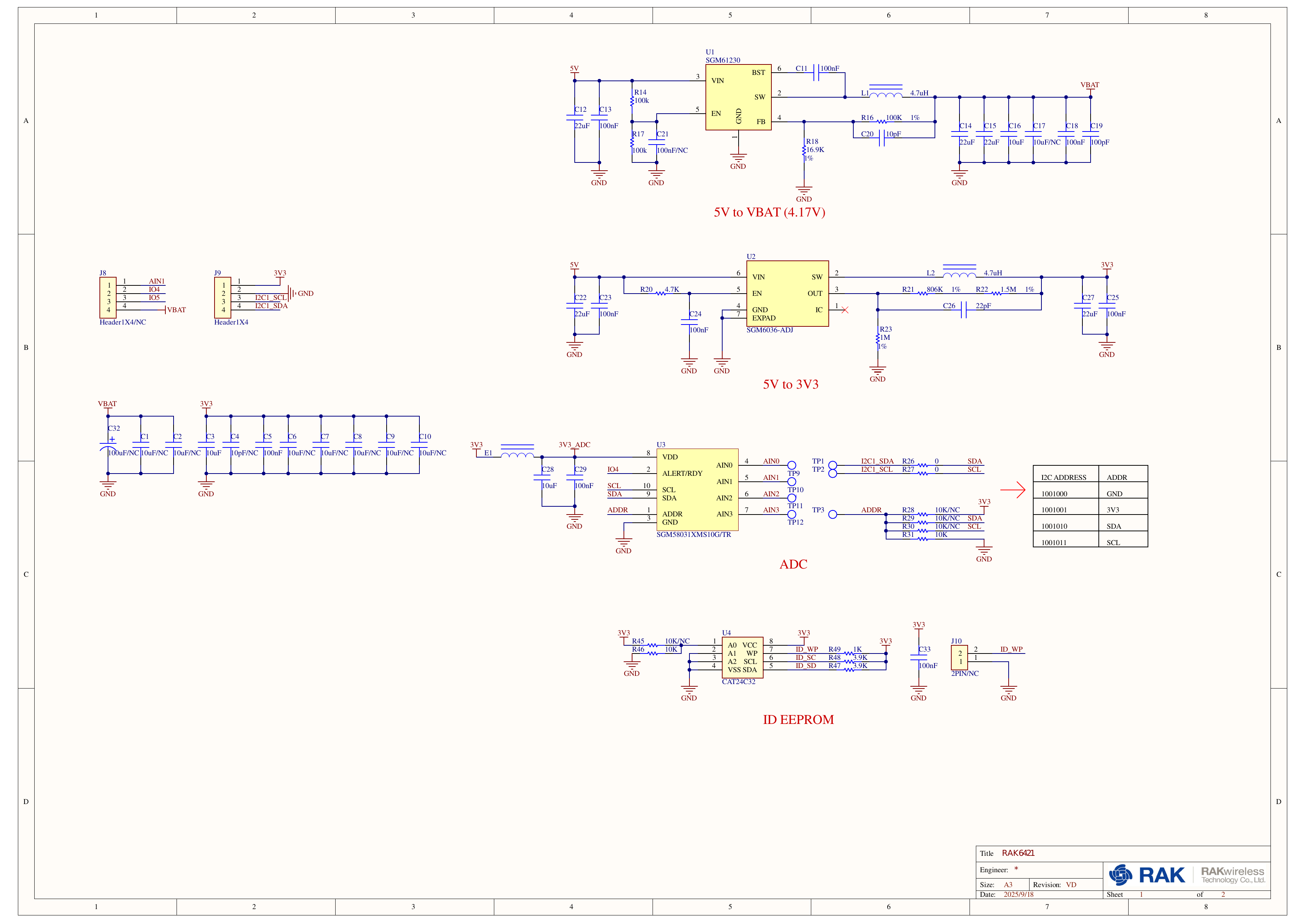 Figure 1: RAK6421 WisBlock Hat for Raspberry Pi Schematic Page 1
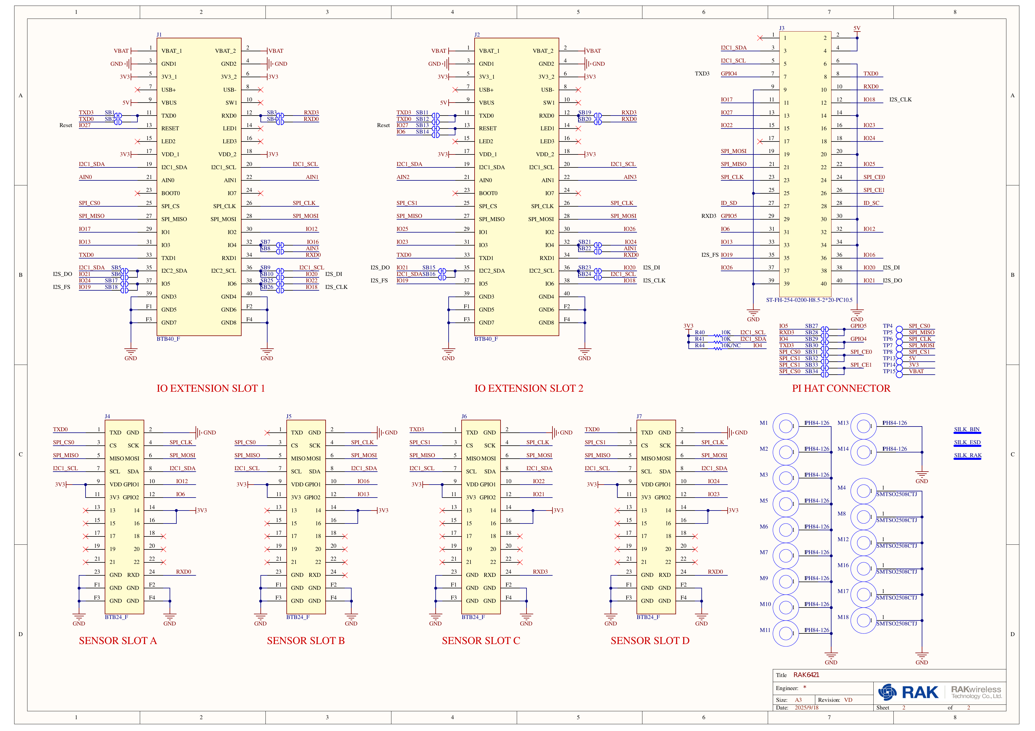 Figure 1: RAK6421 WisBlock Hat for Raspberry Pi Schematic Page 2
Mechnical
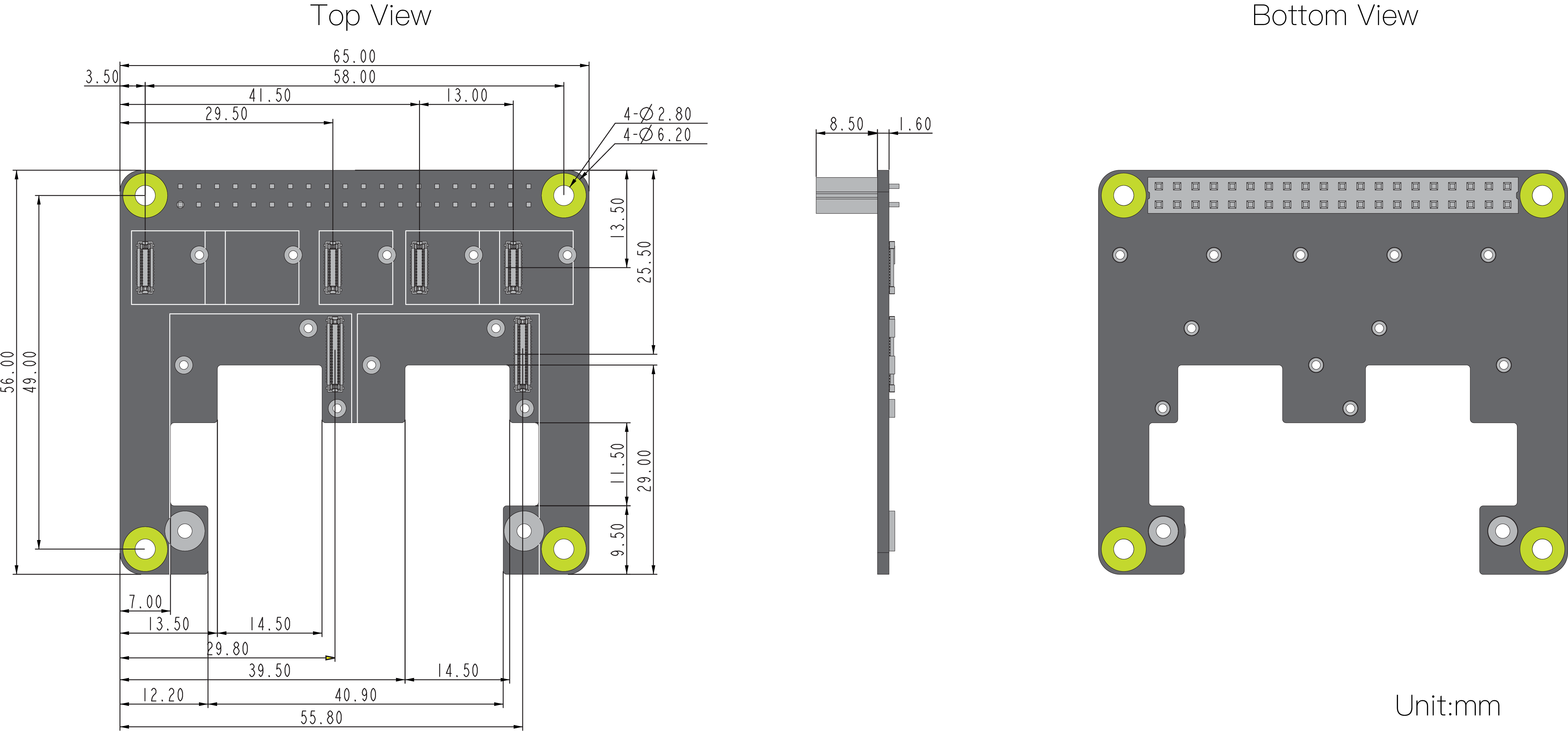 Figure 1: RAK6421 WisBlock Hat for Raspberry Pi Mechanical Drawing