RAK8213 WisLink Cellular mPCIe Quick Start Guide
Prerequisites
What Do You Need?
The following two sections will provide a list of the components and tools you need to get started with the development board. Some of those are included in the package, others you need to provide yourself.
Hardware Tools
- RAK8213 WisLink Cellular mPCIe
- Raspberry Pi 3/4
- RAK8213 Pi HAT
- LTE and GPS antennas (included)
- Hologram SIM card
Software Tools
- Balena Etcher (a tool for burning the firmware on the SD card)
- PuTTY (a Windows tool for SSH, required to connect to the Gateway)
- Latest RAK8213 Firmware
Device Firmware Setup
An easy and quick way to have a fully functional gateway is by using a Precompiled Firmware Image provided. In this document, is the step by step instructions on how to install the Image into your SD card used for the gateway.
Burn the Latest Firmware
- Download the latest firmware, which is based on the Raspbian OS.
- You need to use an image writing tool to install the firmware on the SD Card. For this, you will be using Etcher, which is an open source utility used for burning image files.
- Insert your SD Card into the SD Card reader and plug it into your Computer.
- Open the Etcher Software, and select the downloaded image file thru the ( Label - 1 ) button in Figure 1.
Your SD card should be automatically detected by the Etcher software in the Label - 2 of Figure 1. If not, secure a proper connection.
Click Flash and wait for a couple of minutes until it displays Flash Complete.
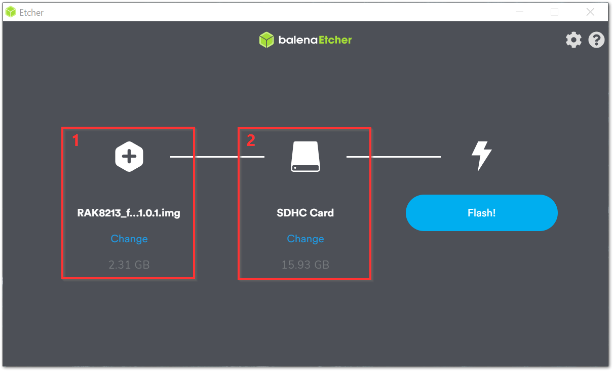 Figure 1: Balena Etcher Software
Assembly Guide
For the RAK8213 module to function as an extension for the Raspberry Pi, you need to assemble several components.
SIM Card
Insert the SIM card in the slot that sits on the back of the RAK8213. Best do this now as later on, it will be more difficult to access.
Mount the RAK8213 Module
Insert your RAK8213 module into the mPCIe slot on the RAK8213 Pi HAT. Make sure the card fits snugly into the connector. It should end up sticking out at an angle of 45°. Gently press it down and fasten it with two (2) screws. If you have positioned the card right, the screw holes on the RAK8213 will match the ones on the RAK8213 HAT. Use Figure 2 as a reference.
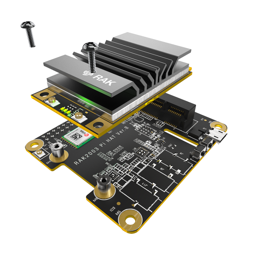 Figure 1: Assembly of the NB-IoT Module and the HAT
Antennas
The module comes with two (2) antennas: Cellular and GPS. Both have pigtail cables that have uFL connectors, which fit onto the corresponding ports on the RAK8213. The GPS antennas are on the right when looking at the module from the side where the BG96 is. Match each antenna to its port and gently press it until the connectors fit one to the other.
It is not recommended to have the device powered with the antennas detached. This might damage the circuitry.
Mount the HAT
Take the RAK8213 HAT, which now has the RAK8213 securely sitting on top, and insert it over the Raspberry Pi. Both the Pi and the HAT have a 40-pin connector that should fit together snuggly when pressed on top of each other.
Power the RAK8213
The RAK8213 requires additional power via the Micro USB port on the RAK8213 Pi HAT.
For the above-noted purpose, attach a standard Micro USB to USB cable connecting one of the Raspberry’s USB ports to the Micro USB port on the RAK8213 HAT.
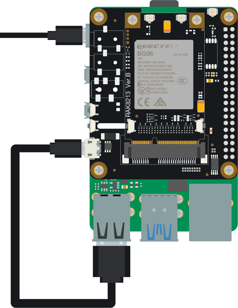 Figure 1: Assembly of the NB-IoT Module and the HAT
SD card
Insert the SD card with the Firmware you flashed in the previous step into the SD card slot on the bottom of the Raspberry Pi.
Boot
Power the Raspberry Pi via the Micro USB port (Pi3) / USB type C port (Pi4). As this is going to be the first time to boot the OS, wait for a couple of minutes for everything to set up.
It is recommended to use at least a 2 A power supply.
Access the Gateway
Wi-Fi AP Mode
By default, the firmware is configured to operate the Raspberry Pi in Wi-Fi AP mode, which means that you should be able to find an SSID named “Rakwireless_XXXX” on the Wi-Fi network list, for example:
 Figure 1: RAKWireless Access Point
- The default password for the AP: rakwireless.
- The default IP address of the Raspberry Pi: 192.168.230.1. This is also the address you will be using to SSH into the OS.
- There is no need to configure the IP address of your PC as it will be assigned automatically via the DHCP server.
Log into the Raspberry through SSH
1. Windows OS
SSH (Secure Shell) is used to login to a remote machine and execute commands. There are several free and good SSH Clients available such as Putty, BitVise SSH Client, and MobaXterm. You are free to choose one that fits your needs, however, in this guide, you will be using Putty.
After installation, open Putty and connect with the OS through Wi-Fi AP mode. The IP address is 192.168.230.1.
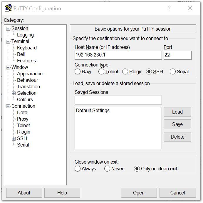 Figure 1: Putty Software for SSH in Windows
- Click open and it will prompt you to enter the username and password.
- The default username: pi
- The default password: raspberry
Upon successful login, you should see the initial screen with the messages notifying you that you should change your password. Refer to Figure 6.
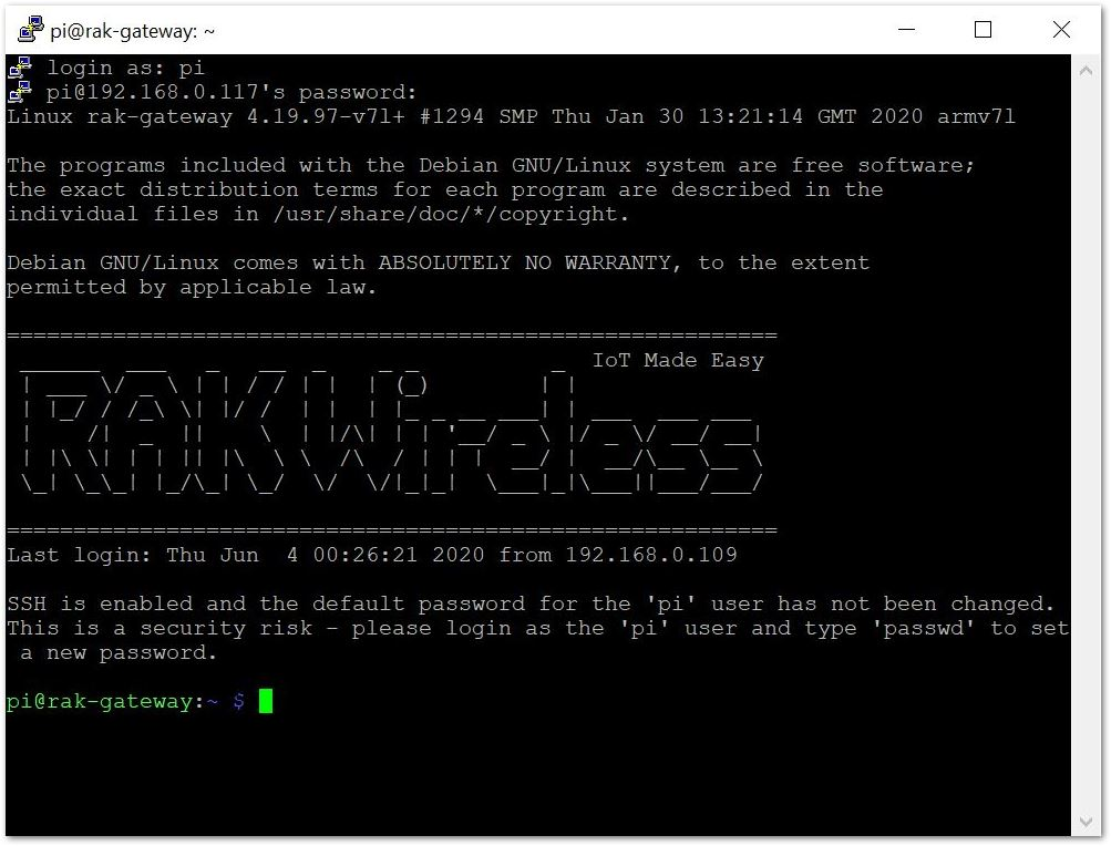 Figure 1: Command line after login
2. Mac OS
Open the terminal of Mac OS. Then, launch the Terminal application found in this directory: /Applications/Utilities/. You can also launch it from Spotlight by hitting Command + Spacebar and typing “Terminal” and then return:
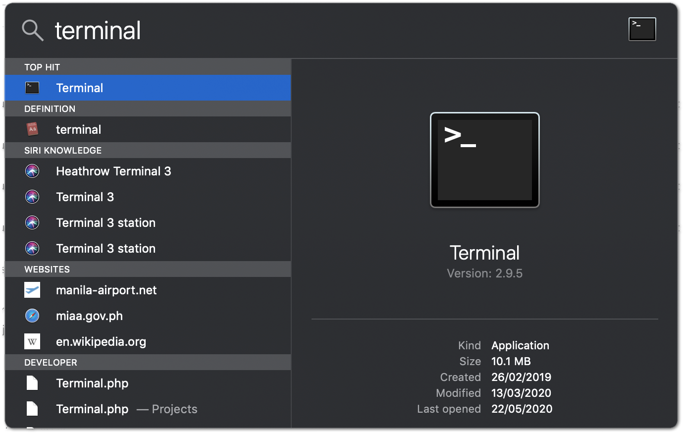 Figure 1: Mac OS Terminal
Open the terminal of Mac OS. Enter root mode by typing the following command: sudo -i.
 Figure 1: SSH in Mac OS
- If you are not in root mode, enter
ssh pi@192.168.230.1in the terminal to login to your gateway. The default password is raspberry.
 Figure 1: Log into the Raspberry
3. Linux
If you are using Linux the procedure is the same as the one for Mac OS.
Product Configuration
Connecting to a Network
As you now have direct access to the Raspberry and its console you can proceed to configure it to connect to a network, rather than act as an AP for other devices.
Instructions and examples are provided in the following sections.
Connect through Wi-Fi (Raspberry Pi Built-in)
Now that you are logged into Raspberry, you can proceed to access the configuration tool that comes with the RAKwireless firmware. To do so, execute the following steps:
- Enter the following command and select option 1 Configure WIFI.
sudo qmi-config
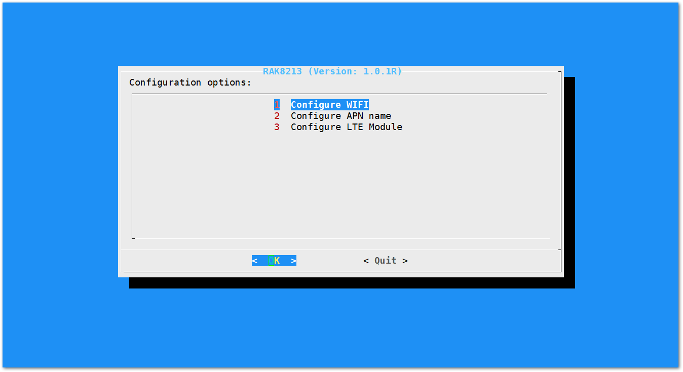 Figure 1: Main configuration menu
- Select Option 2 Enable Client Mode/Disable AP Mode and click OK. This will let you use the device as a Wi-Fi client rather than AP so you can connect to a network.
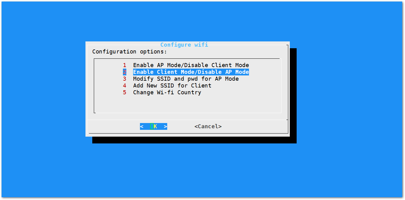 Figure 1: Wi-Fi Configuration Options
As shown in Figure 11, there are five (5) different Wi-Fi configuration options you can choose from.
- Enable AP Mode/Disable Client Mode - the gateway will work in Wi-Fi Access Point Mode after rebooting while the Wi-Fi Client Mode will be disabled (this is the default mode).
- Enable Client Mode/Disable AP Mode - the gateway will work in Wi-Fi Client mode after rebooting, while Wi-FI AP Mode will be disabled.
- Modify SSID and pwd for AP Mode - used to modify the SSID and password of the Wi-Fi AP. Only works if the Wi-Fi AP Mode is enabled.
- Add New SSID for Client - this is used if you want to connect to a new Wi-Fi Network. Only works in Wi-Fi Client mode.
- Change Wi-Fi Country - this is used to modify the Resident Country to match with Wi-Fi standards.
To enable the Wi-Fi Client Mode, you have to disable first the AP Mode.
- A window will pop-up, and then click OK.
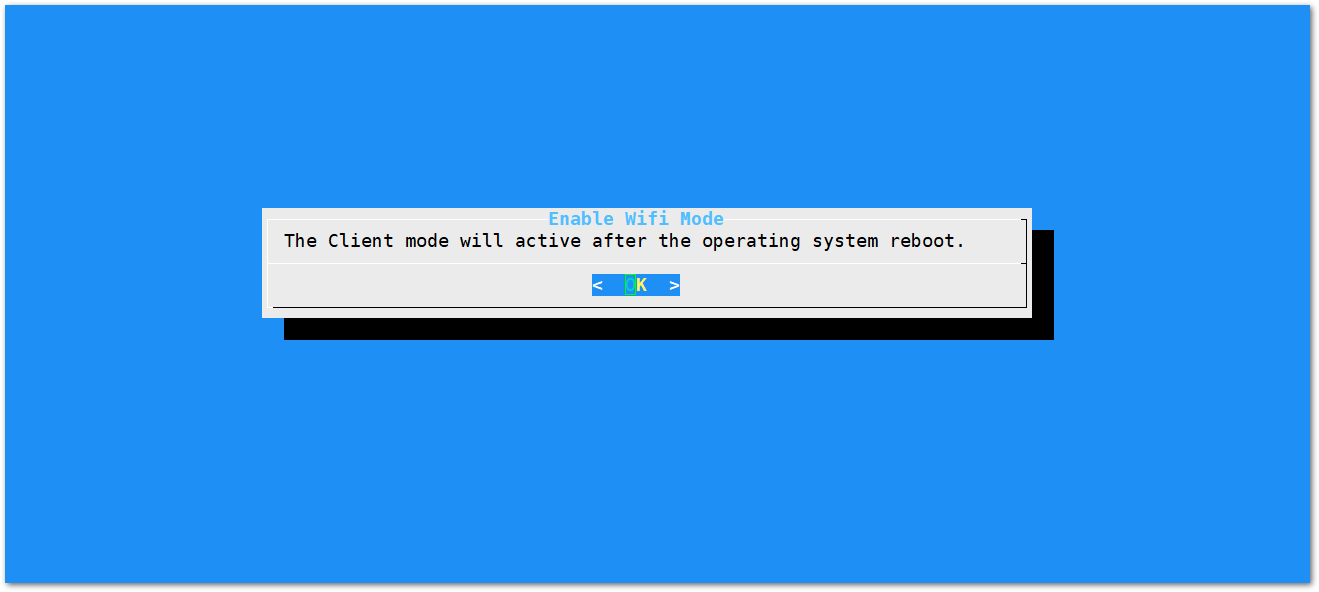 Figure 1: Client mode enabled
- Once Wi-Fi AP Mode is enabled, you will automatically return to the main configuration menu (Figure 10). Select option 1 Configure WIFI then choose option 4 Add New SSID for Client.
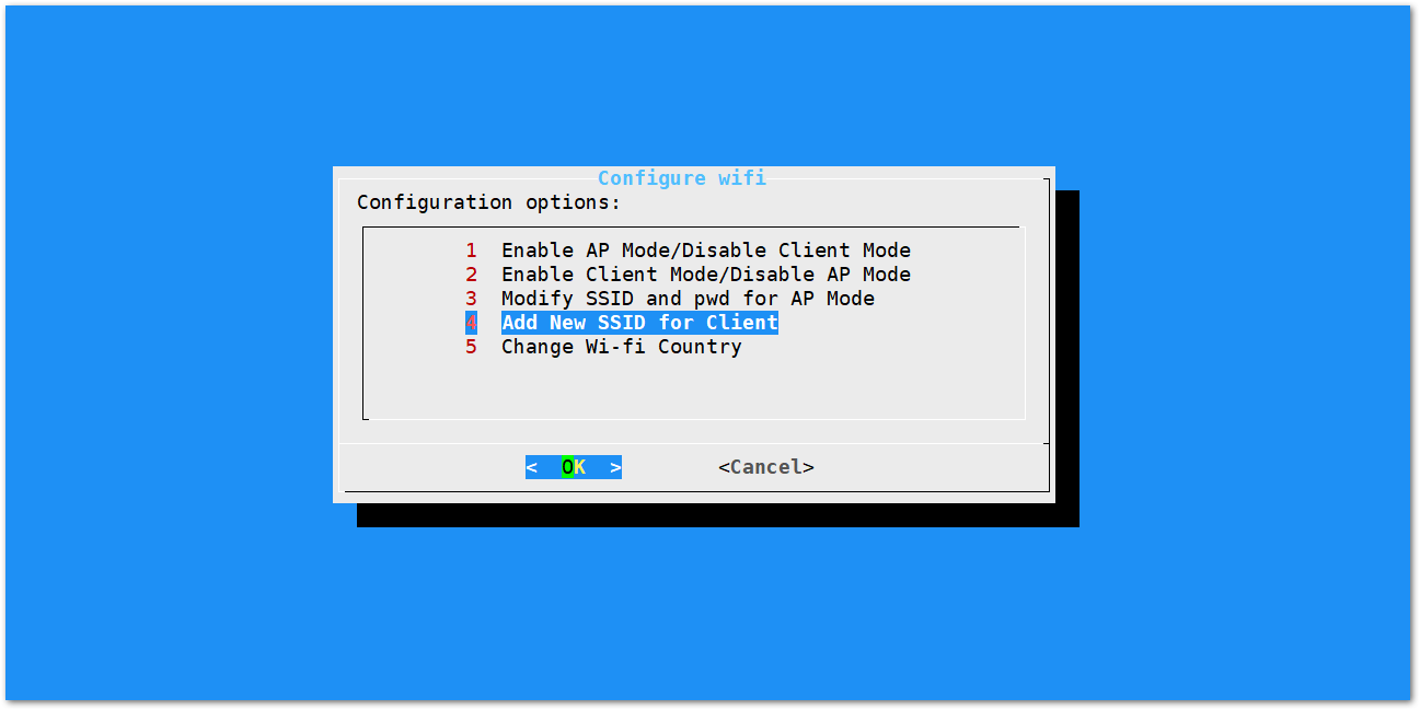 Figure 1: Wi-Fi Settings
- Enter the SSID of the network you want to connect to then click OK.
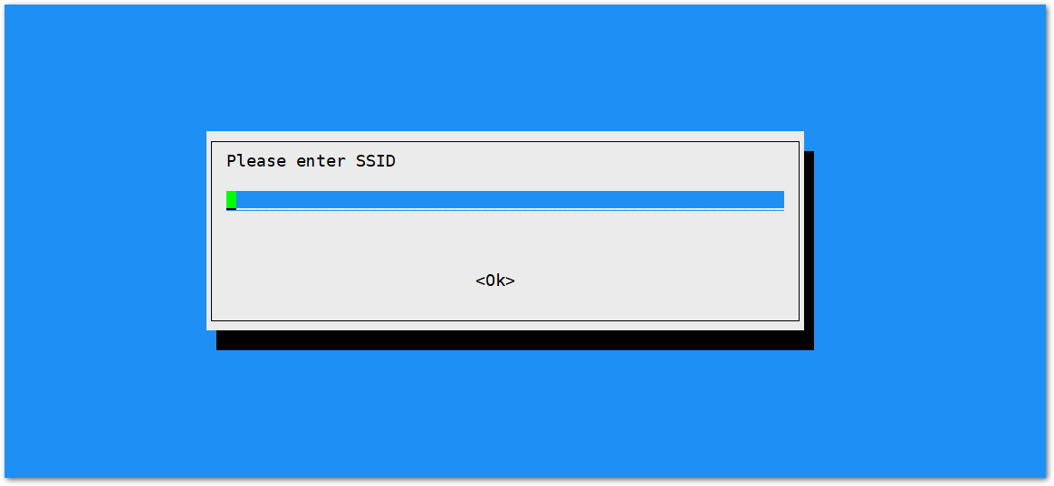 Figure 1: Wi-Fi SSID
- Enter also the password then click OK. Just leave it empty if it has none.
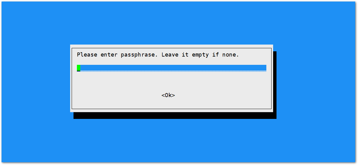 Figure 1: Wi-Fi Passphrase
-
Quit the setup. Click the quit button at the lower right corner.
-
Then, reboot your device. Use the following command so the changes take effect.
sudo reboot
Connect through Cellular (RAK8213 + Hologram SIM)
Before connecting to a cellular network, you should have a SIM card first. After that, you need to configure the BG96 to connect it to the provider. This requires connecting to the BG96 via the USB interface and sending over a few AT commands to set the right values for several parameters.
For this example, you are going to use a Hologram SIM and configure the BG96 with minicom.
- To start with, execute the following command:
sudo minicom -D /dev/ttyUSB3
This will start minicom, a Linux tool that allows serial communication. In this case, the minicom allows the serial communication with the USB interface that the BG96 is connected to.
-
Make sure to turn the local Echo so you can input the command with the Ctrl+A, followed by pressing Z to get to the Command summary.
-
Press E to turn local echo on/off.
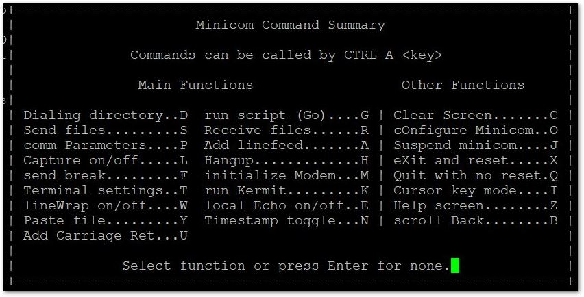 Figure 1: Minicom Command Summary
The following code block is a summary of the commands you need to execute in the same order. Each code is discussed and an example output is provided at the end of this section.
AT+CPIN? // Checks the SIM card status.
AT+QCFG="nwscanmode",1,1 // Chooses only GSM (disables LTE).
AT+COPS=? // Lists the available network providers.
AT+COPS=1,2,"28403",0 // Forces the connection to Vivacom BG.
AT+COPS? // Queries the connected web server information.
AT+QICSGP=1,1,"hologram","","",1 // Configures PDP context by adding the APN keys.
AT+QIACT=1 // Activates the APN network
AT+QIOPEN=1,0,"TCP","cloudsocket.hologram.io",9999,0,1
AT+QISEND=0,50 // Sends data, data length is 50.
{"k":"YOUR_DEVICE_KEY_HERE","d":"RAKwireless!","t":"_TOPIC1_"} // Sends
AT+QISEND=0,0 // Query data is sent successfully.
AT+CPIN?
Checks if the SIM card has a PIN code. In the case of the Hologram SIM, there shouldn’t be one, however, it is good practice to check. If there is no PIN, the output is as follows:
+CPIN: READY
AT+QCFG="nwscanmode",1,1
Gives you options on what technology to use when scanning for networks. You can use GSM, LTE, or both as the BG96 has them supported. For this guide, GSM is selected as the local providers have no NB-IoT support anyways, plus selecting only one option dramatically speeds up the next step. The response should be as follows:
OK
AT+COPS=?
Lists all the available network providers in your area. By default, it automatically picks one network provider, but, you are going to make a manual choice. The response the command returns for the region the tutorial produced is as follows:
+COPS: (1,"Vivacom BG","Vivacom","28403",0),(1,"Telenor BG","Telenor","28405",0)
OK
As shown above, there are 2 operators available: Vivacom BG and Telenor. Now that this information is present, it can be used for the next command.
AT+COPS=1,2,"28403",0
Selects the network with the numeric identification of 28403 (easier to enter than a name). The parameters are as follows:
- 1 - for Manual selection
- 2 - for numeric GSM area location identification number
- 28403 - for the identification number of Vivacom BG
- 0 - for GSM area access technology
If there are no errors, the output is as follows:
OK
AT+COPS?
Checks the network status. If the changes took effect, it should reflect the information you entered in the previous command.
+COPS: 1,2,"28403",0
OK
AT+QICSGP=1,1,"hologram","","",1
Sets the AP (access Point). The parameters are as follows:
- 1 - context ID
- 2 - for IPv4
- "hologram" - access point name (particular for this example only)
- "" - user name, empty as there isn’t one.
- "" - password, empty as there isn’t one.
- 1 - authentication method PAP.
If there are no errors the output is as follows:
OK
AT+QIACT=1
Confirms and activates the APN network. Expected output is as follows:
OK
AT+QIOPEN=1,0,"TCP","cloudsocket.hologram.io",9999,0,1
Opens a TCP session to the hologram servers so you can send your data. The most relevant parameters are the three (3) listed below, which you need to change if you use a provider other than Hologram:
- "TCP" - type of protocol
- "cloudsocket.hologram.io" host
- "9999" port
If there are no errors, the output should be as follows:
OK
+QIOPEN: 0,0
AT+QISEND=0,50
In this command, the message is to be sent. In this example, the message has a length of 50 bytes. After the command is executed, you are left with a prompt to enter your message:
>
You need to adhere to a Hologram specific format, in short it is as follows:
{"k":"YOUR_DEVICE_KEY_HERE","d":"RAKwireless!","t":"_TOPIC1_"}
- "k" - a string of 8 characters is used as Device Key for authentication.
- "d" - a string of data that is the Message Payload.
- "t" - a string or an array of strings with message tags to be used as Message Topics.
You will need a Device Key that ties to your Hologram SIM (this tutorial assumes you have already registered and activated your Hologram SIM). To create one, execute the following steps:
-
Open the Hologram Dashboard.
-
Go to the Webhooks section.
-
Under Data Engine, press the Show Device Key button.
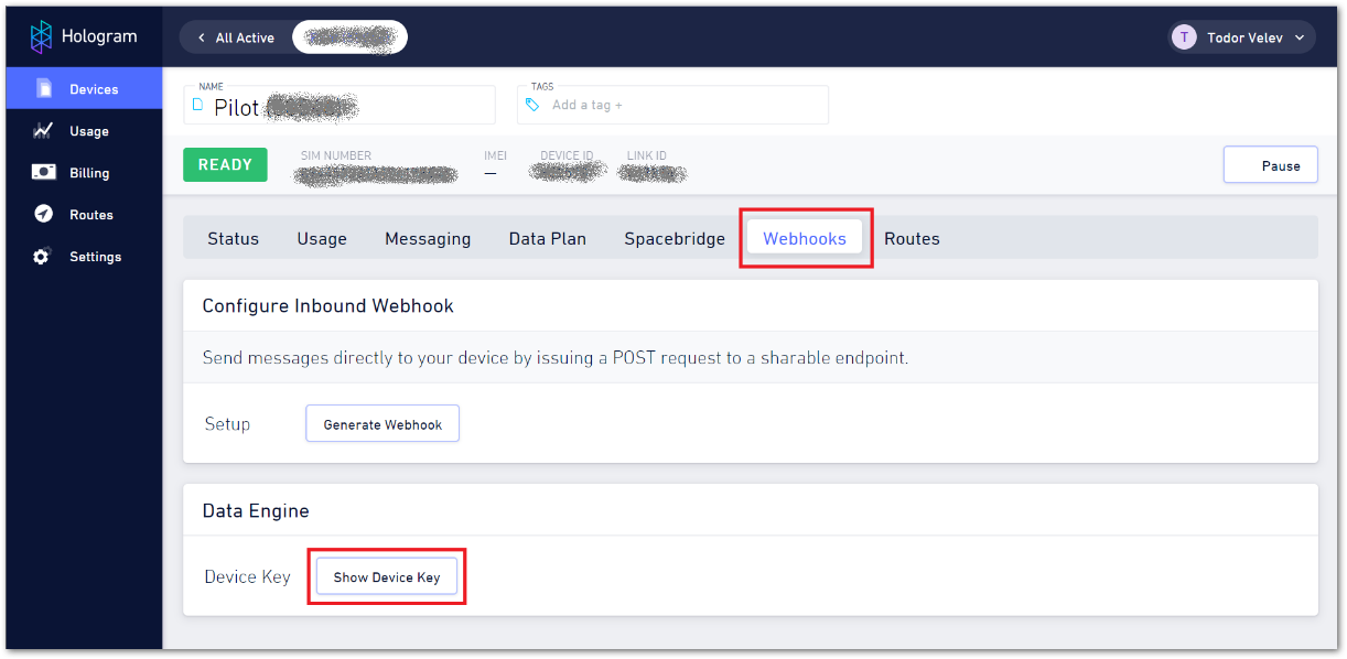 Figure 1: Hologram Dashboard Webhooks
- In the Router credentials window, click the Generate New Device Key button to generate a key. Then, click the Copy Key button.
 Figure 1: Hologram Dashboard Device Key
Now that you have your key, you can replace it with the k parameter. You can leave the message and the topic as per the example, which leads to the code line to follow if you use the copied key in Figure 18.
The end message for this example is as follows:
{"k":"$pU1Yg}.","d":"RAKwireless!","t":"_TOPIC1_"}
If the message is sent successfully, the response is as follows:
SEND OK
Command Summary
Listed below is the summary of commands with their corresponding outputs:
AT+CPIN?
+CPIN: READY
OK

AT+QCFG="nwscanmode",1,1
OK

AT+COPS=?
+COPS: (1,"Vivacom BG","Vivacom","28403",0),(1,"Telenor BG","Telenor","28405",0)
OK

AT+COPS=1,2,"28403",0
OK

AT+COPS?
+COPS: 1,2,"28403",0
OK

AT+QICSGP=1,1,"hologram","","",1
OK

AT+QIACT=1
OK

AT+QIOPEN=1,0,"TCP","cloudsocket.hologram.io",9999,0,1
OK
+QIOPEN: 0,0

AT+QISEND=0,50
> {"k":"YOUR_DEVICE_KEY_HERE","d":"RAKwireless!","t":"_TOPIC1_”}

AT+QISEND=0,0
