RAK7431 MQTT Integration and Remote Configuration
The RAK7431 WisNode Bridge Serial can exchange application data with an external MQTT client through the MQTT interface of the Built-in Network Server on a compatible RAKwireless WisGate gateway.
Using this integration, you can:
- Subscribe to RAK7431 uplink data through MQTT.
- Publish LoRaWAN® downlink messages through MQTT.
- Remotely read or modify polling, DTU, and LoRaWAN settings on the RAK7431.
This guide uses MQTT.fx as an example MQTT client.
Prerequisites
Before starting:
- The RAK7431 is registered with and connected to the gateway Built-in Network Server.
- The gateway MQTT service is available.
- An MQTT client is installed. The examples in this guide use MQTTfx tool .
For the initial LoRaWAN setup, refer to the RAK7431 Quick Start Guide.
MQTT Topic Templates
Application/{{application_ID}}/device/{{device_EUI}}/join
Application/{{application_ID}}/device/{{device_EUI}}/rx
Application/{{application_ID}}/device/{{device_EUI}}/tx
Application/{{application_ID}}/device/{{device_EUI}}/ack
Application/{{application_ID}}/device/{{device_EUI}}/status
MQTT Integration
Connect an MQTT Client
- Install and open MQTT.fx.
- After installation, the MQTT Client must be configured. Select local mosquitto from the drop-down list and click the edit connection profiles icon marked in the image below to open the settings page.
 Figure 1: MQTT.fx connection profile
 - On the next window, input the Broker Address and Broker Port. If the Client ID is empty press Generate. Then click OK.
- Broker Address: Address of MQTT server – the gateway IP.
- Broker Port: Consistent with MQTT Broker Port set by the gateway - by default 1883.
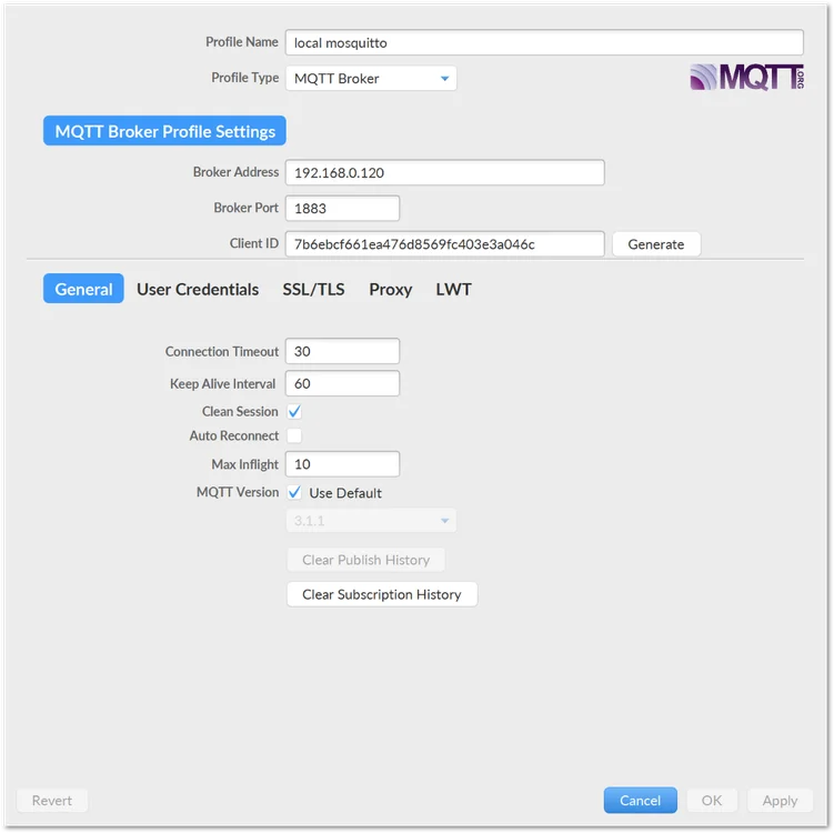 Figure 1: MQTT.fx broker settings
- Click on the Connect button. The green dot indicates that the connection is successfully subscribed to the MQTT Broker.
 Figure 1: MQTT.fx connected to the broker
Subscribe to RAK7431 Uplink Data
- Open the Subscribe tab.
- Enter the required topic. To subscribe to all available topics for testing, use:
# - Click Subscribe.
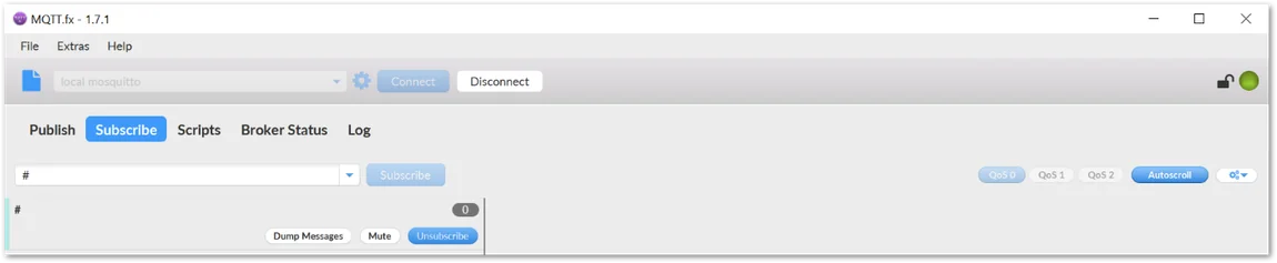 Figure 1: Subscribe to MQTT topics using a wildcard
When the RAK7431 sends data, the corresponding MQTT message appears in the subscribed topic.
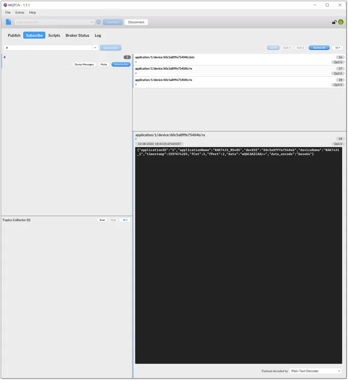 Figure 1: RAK7431 uplink data received through MQTT
Configure the Payload Display Format
Depending on the Built-in Network Server application settings, the uplink data field can be represented in Base64.
To change the application decode format:
- In the gateway Web UI, go to LoRa > Applications.
- Open the application used by the RAK7431.
- Open the application configuration.
- Select the required Decode Type.
- Save the changes.
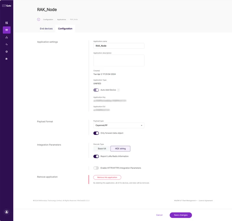 Figure 1: Configure the application payload decode type
Send Remote Configuration Commands
The RAK7431 supports remote configuration through LoRaWAN downlink commands.
When using the Built-in Network Server MQTT interface, publish the downlink message to:
Application/{{application_ID}}/device/{{device_EUI}}/tx
Remote configuration commands use FPort 129.
Example:
{
  "confirmed": true,
  "fPort": 129,
  "data": "030001000901010300000002C40B"
}
| Parameter | Description |
|---|---|
confirmed | Requests a confirmed downlink. |
fPort | Remote configuration port. Use 129. |
data | Remote configuration command in hexadecimal format. |
Polling Task Management
Add a Scheduled Polling Task
| Field | Length / Content |
|---|---|
DTU_CMD | 0x03 |
MSER | 2 bytes |
MDATA_LEN | 2 bytes |
TASK_ID | 1 byte |
DATA | Variable length |
MDATA_LEN does not include the message header.
Example:
{
  "confirmed": true,
  "fPort": 129,
  "data": "030001000901010300000002C40B"
}
A successful response uses command code 0x83.
83000100010101
Remove a Scheduled Polling Task
Example:
{
  "confirmed": true,
  "fPort": 129,
  "data": "040001000101"
}
A successful response uses command code 0x84.
84000100010101
Read a Scheduled Polling Task
Example:
{
  "confirmed": true,
  "fPort": 129,
  "data": "050001000101"
}
A successful response uses command code 0x85 and includes the task ID and task data.
8500010009010103000000002C40B
LoRaWAN Configuration
Read the LoRaWAN Configuration
Use command code 0x06.
{
  "confirmed": true,
  "fPort": 129,
  "data": "0600010000"
}
A successful response uses command code 0x86 and returns the following fields:
| Field | Description |
|---|---|
DATARATE | Data rate setting |
TXPOWER | Transmit power setting |
CONFIRM | Confirmed uplink setting |
RETRY | Maximum retry count |
ADR | Adaptive Data Rate setting |
DUTY CYCLE | Duty-cycle setting |
Change the LoRaWAN Configuration
Use command code 0x07.
{
  "confirmed": true,
  "fPort": 129,
  "data": "070001000601050103010"
}
The example changes the data rate to 1 and transmit power to 5.
A successful response uses command code 0x87.
8700010000
Reset the LoRaWAN Configuration
{
  "confirmed": true,
  "fPort": 129,
  "data": "1D00010000"
}
A successful response uses command code 0x9D.
9D00010000
DTU Configuration
Read the DTU Configuration
Use command code 0x08.
{
  "confirmed": true,
  "fPort": 129,
  "data": "0800010000"
}
A successful response uses command code 0x88 and includes:
| Field | Description |
|---|---|
POLL ENABLE | Scheduled polling status |
POLL PERIOD | Polling period in seconds |
BUS TIMEOUT | RS485 bus timeout |
RETRY | Retry count after bus timeout |
RS485 | RS485 bus parameters |
Change the DTU Poll Configuration
Use command code 0x09.
{
  "confirmed": true,
  "fPort": 129,
  "data": "09000100080100000E10010050"
}
The example changes the polling period to one hour.
A successful response uses command code 0x89.
8900010000
Reset the DTU Configuration
{
  "confirmed": true,
  "fPort": 129,
  "data": "1E00010000"
}
A successful response uses command code 0x9E.
9E00010000


