RAK7431 RS485 Data Transmission and Polling
The RAK7431 WisNode Bridge Serial supports configurable RS485 data transmission and scheduled Modbus polling. These settings determine how RS485 response data is packaged for LoRaWAN® transmission and how the RAK7431 actively queries connected RS485 devices.
Use this guide after the RAK7431 has been connected to the RS485 device and successfully joined a LoRaWAN network.
Data Transmission Mode
When the RS485 interface operates in Modbus mode, the returned RS485 data can be transmitted using either transparent mode or non-transparent mode.
- Transparent mode: The Modbus response data received from the RS485 device is forwarded directly in the LoRaWAN payload.
- Non-transparent mode: The Modbus response data is encapsulated with additional protocol information before being transmitted over LoRaWAN.
Non-transparent mode is enabled by default.
Use the following command to configure the transmission mode:
AT+TRANSPARENT=n
| Value | Mode |
|---|---|
0 | Non-transparent mode |
1 | Transparent mode |
The change takes effect immediately.
Scheduled Polling
When scheduled polling is enabled, the RAK7431 periodically sends the configured Modbus polling instructions to connected RS485 devices and forwards the returned data over LoRaWAN.
Enable or Disable Scheduled Polling
AT+ENABLEPOLL=n
| Value | Description |
|---|---|
0 | Disable scheduled polling |
1 | Enable scheduled polling |
Scheduled polling is enabled by default. A restart is required after changing this setting.
Configure the Polling Cycle
Use AT+POLLPERIOD to configure the interval between polling cycles.
For example, to set the polling cycle to 60 seconds:
AT+POLLPERIOD=60
The updated polling period takes effect after the next polling cycle or after the device restarts.
The RAK7431 can store up to 32 polling instructions, with each instruction supporting up to 128 bytes.
Add Modbus Polling Instructions
To add polling instruction, execute the AT command:
AT+ADDPOLL=<n>:<xxxx>
| Parameter | Description | Value |
|---|---|---|
n | Polling instruction ID | Device-supported polling instruction ID |
xxxx | Polling instruction content in hexadecimal format | Up to 128 bytes |
According to the temperature and humidity register address of the temperature and humidity sensor in the example and the RS485 address, the polling instruction should be:
AT+ADDPOLL=1:010300000002C40B
Example: If you have added multiple RS485 temperature and humidity sensors, continue to increase the polling instructions based on the RS485 address and register address, for example:
- RS485 Temperature and humidity sensor addr: 01, Polling 1: 010300000002C40B
- RS485 Temperature and humidity sensor addr: 04, Polling 2: 040300000002C45E
- RS485 Temperature and humidity sensor addr: 08, Polling 3: 080300000002C492
- RS485 Temperature and humidity sensor addr: 0F, Polling 4: 0F0300000002C525
AT+ADDPOLL=1:010300000002C40B
AT+ADDPOLL=2:040300000002C45E
AT+ADDPOLL=3:080300000002C492
AT+ADDPOLL=4:0F0300000002C525
Verify RS485 Polling and LoRaWAN Transmission
After the polling instructions are configured, check the serial output:
- DTU Tx: Polling request sent to the RS485 device.
- DTU Rx: Response received from the RS485 device.
- LoRa Tx: RS485 data transmitted over LoRaWAN.
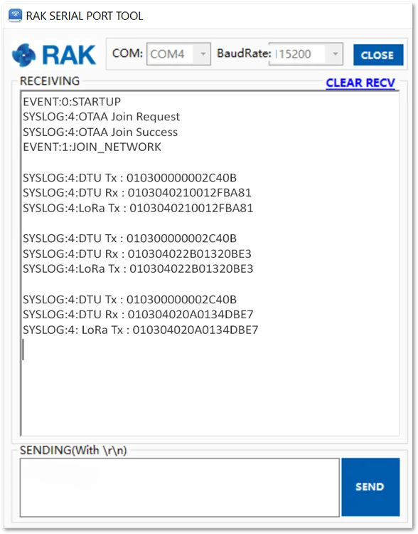 Figure 1: RS485 data transmitted in transparent mode
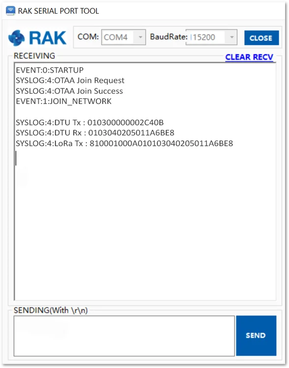 Figure 1: RS485 data transmitted in non-transparent mode
For the temperature and humidity example:
- Humidity:
0x0210= 528, corresponding to 52.8% RH. - Temperature:
0x012F= 303, corresponding to 30.3 °C.


