RAK7432/RAK7434 Quick Start Guide
This guide walks you through connecting an analog sensor to the RAK7432/RAK7434 WisNode Bridge Analog, configuring the device and connecting it to a LoRaWAN Network Server. The two variants support different analog input types:
- RAK7432: 4–20 mA analog input
- RAK7434: 0–5 V analog input
Prerequisite
Before starting, prepare the following hardware and software.
Hardware
- RAK7432/RAK7434
- Compatible analog sensor
- Micro USB cable
- Gateway in range, for testing
- A Windows/Mac OS/Linux computer
Software
Connect the RAK7432/RAK7434 to an Analog Sensor
Power Interface Configuration
The RAK7432/RAK7434 can be powered through either the DC input terminals or the Micro USB port.
- DC input: Connect a 12–24 VDC power supply to the
VINandGNDterminals. - Micro USB: Connect the device to a computer or a 5 V / 500 mA USB power source.
The Micro USB port is also used as the device configuration interface.
The Micro USB port can be used only for powering the device. It cannot provide power to VOUT and power other devices in the other connected 4-20 mA/0-5 V.
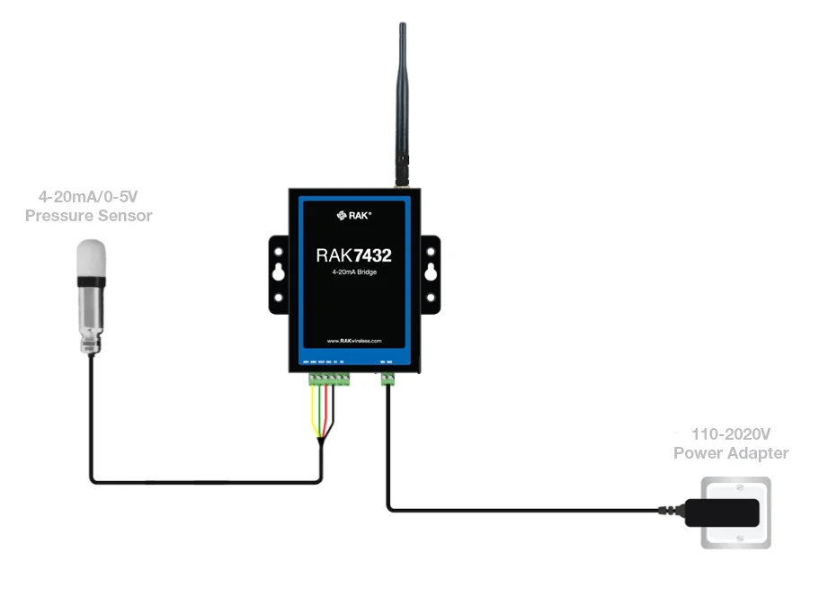 Figure 1: RAK7432/RAK7434 bridge with connected sensor and power supply
Data Interface Configuration
Connect the analog sensor according to the RAK7432/RAK7434 interface definition.
- For RAK7432, connect a compatible 4–20 mA output sensor.
- For RAK7434, connect a compatible 0–5 V output sensor.
The VOUT on the data interface can supply external power to the analog sensor (only when the device is powered from the DC input). The VOUT output voltage is the same as the DC input voltage VIN.
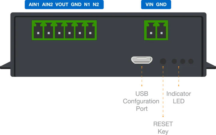 Figure 1: RAK7432/RAK7434 interface pin definition
LoRaWAN Network Configuration
The RAK7432/RAK7434 WisNode Bridge Analog communicates through a standard LoRaWAN network and can be registered with a compatible LoRaWAN Network Server.
This guide provides two network configuration examples:
- Built-in Network Server on a RAKwireless WisGate gateway
- The Things Stack Choose the option that matches your deployment.
You only need to complete one of the following network configuration procedures.
Connect to the Built-in Network Server
This section uses the Built-in Network Server on a RAKwireless WisGate gateway to demonstrate LoRaWAN device registration and network connection.
Before starting, ensure that the gateway is powered on, accessible through its Web UI, and configured for the same LoRaWAN frequency region as the RAK7432/RAK7434.
- Log in to the gateway Web UI. For instructions on how to access the Web UI, refer to the user guide for your gateway.
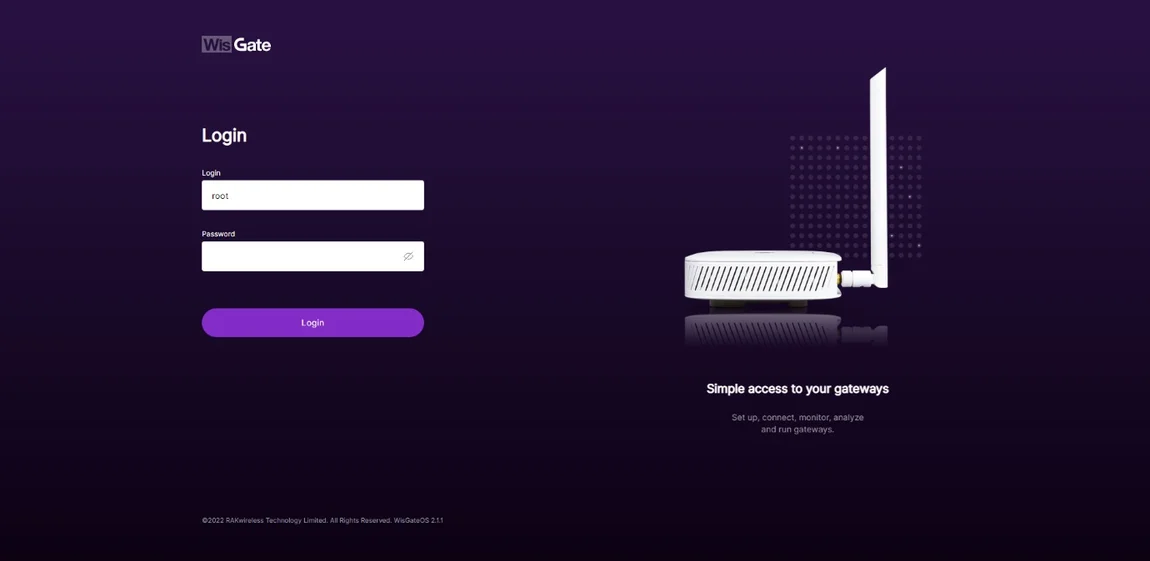 Figure 1: WisGateOS V2 login page
 - Once logged in, head to the LoRa menu.
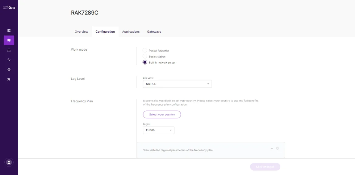 Figure 1: LoRa page
 - By default, the gateway works as a Built-In Network Server. If not, switch the Work mode to Built-in network server.
Create an Application
- Once the gateway is in Built-in network server mode, head to the Applications tab.
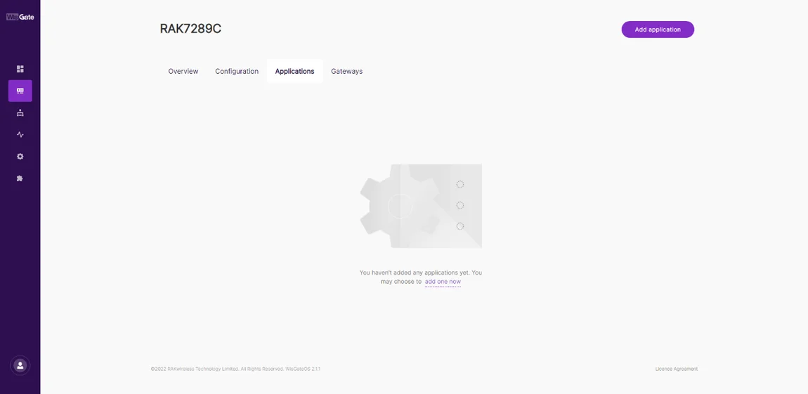 Figure 1: Application page
 - Click the Add application button or add one now link to add a new application. On the new page fill in the following information.
- Application name - type a name for the application.
- Application description - optionally you can write a description of the application.
- Application Type - from the drop-down menu select the type of application.
- Unified Application key - all devices will use the same application key. Selecting this option pops up an Application Key field. You can type your application key there or use the Autogenerate button to generate one.
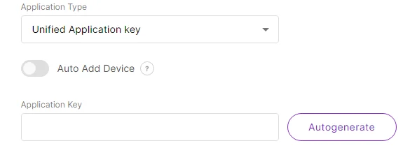 Figure 1: Unified application key
The Auto Add Device switch activates an Application EUI field. The device will be automatically added to the application after the application EUI and key verification.
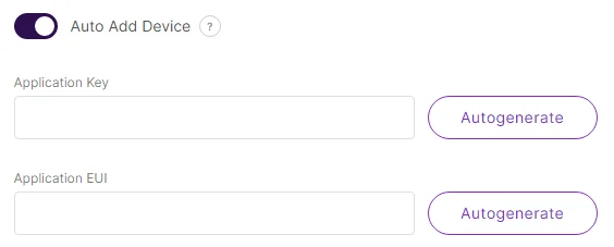 Figure 1: Auto add device
- Separate Application keys – each device will have its own application key. The key is added when registering the device.
- Payload type - from the drop-down select CayenneLPP payload type and turn on the Only forward data object feature.
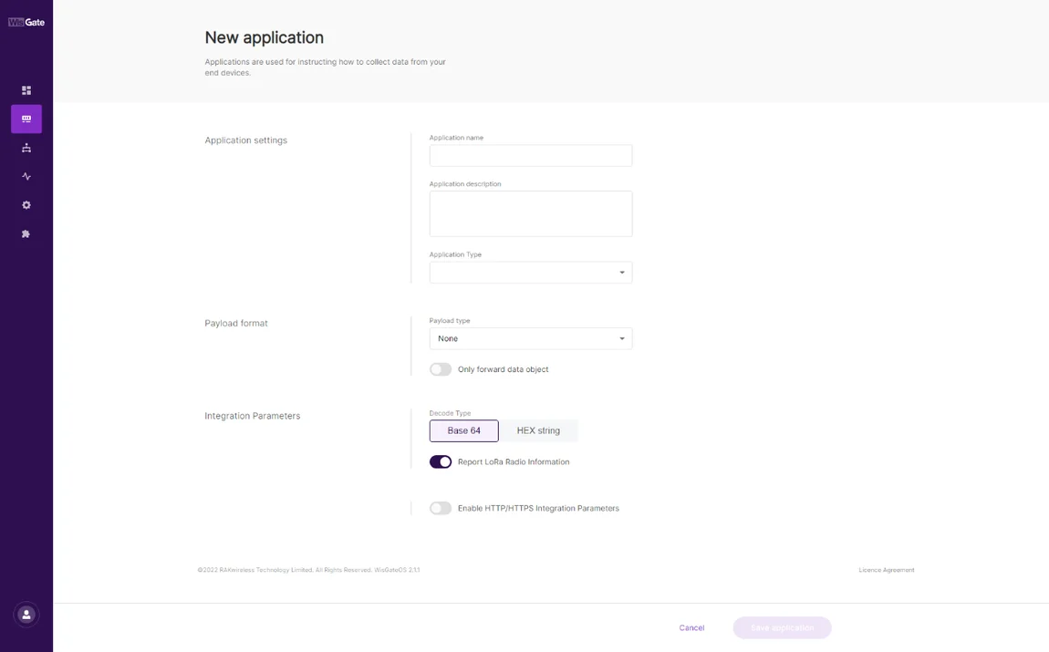 Figure 1: Adding application
- Once this is set, click Save Application to add the application.
- After the application is added, head to the End devices tab. The devices should automatically register upon join request if you are using the Auto Add Device feature.
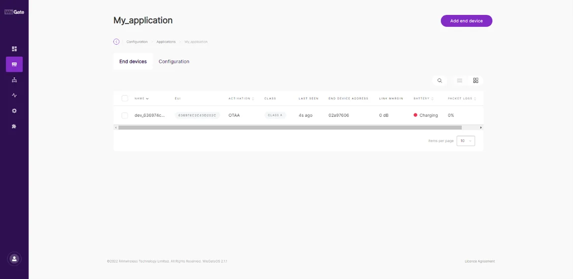 Figure 1: Successfully added end device
If that’s not the case, click the Add end device button. On the End device information page fill in the following information:
- Activation Mode - choose the activation mode of your device:
- OTAA
- ABP - This mode pops up two additional fields:
- Application Session Key
- Network Session Key
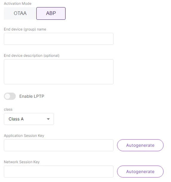 Figure 1: Adding ABP device
- End device (group) name – the name of the device.
- End device description (optional) – optionally, you can add a description for the device.
- Class – the class of the device.
- Frame Counter width – the width of the frame counter. Leave it as default.
- LoRaWAN MAC Version – the LoRaWAN MAC version. V1.0.2 pops up a LoRaWAN Regional Parameters reversion field where you need to select the reversion of the device.
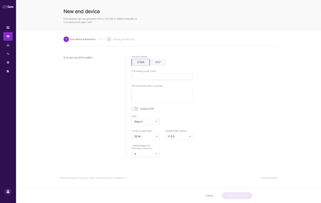 Figure 1: Successfully created application
Add the Device
- Once everything is set, click Add end devices to go to the page and add the device.
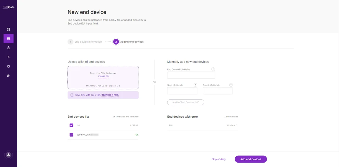 Figure 1: Adding end device
- In the Adding end devices page, type the device EUI at the End Device EUI (main) and click Add to “End Devices list”. If the EUI is correct, the device will show in the End devices list. If the EUI is not correct, the devices will show in the End devices with an error.
- Once the device is added to the End devices list click Add end devices. Confirm you are adding the device.
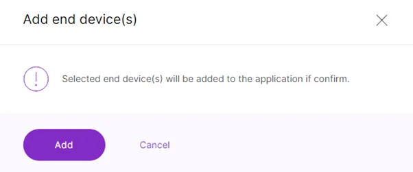 Figure 1: Confirmation message for adding a device
Configure LoRaWAN Parameters
After registering the device with the Network Server, configure the corresponding LoRaWAN parameters on the RAK7432/RAK7434.
- Connect the RAK7432/RAK7434 to a computer using the Micro USB cable.
- Open the RAK Serial Tool and select the correct COM port. The default baud rate is 115200.
- After selecting, press Open.
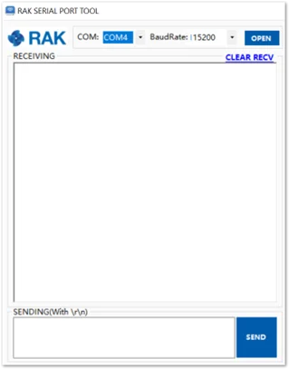 Figure 1: RAK Serial tool
Configure Device Credentials
Configure the DevEUI, AppEUI, and AppKey so that they match the values registered on the Network Server.
AT+DEVEUI=<Device_EUI>
AT+APPEUI=<Application_EUI>
AT+APPKEY=<Application_Key>
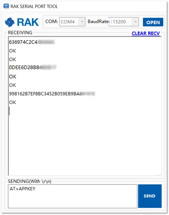 Figure 1: Configuring the RAK7432/RAK7434
Configure the Frequency Region
Set the LoRaWAN frequency region to match the frequency plan used by the gateway and Network Server.
For this demonstration, EU868 will be used. To set the desired regional frequency band, use the command:
AT+REGION=EU868
The frequency region configured on the RAK7432/RAK7434 must match the LoRaWAN frequency plan used by the gateway and Network Server.
Operating and Activation Mode Settings
- Supported operating modes are three: Class A, Class B,and Class C. To set the operating mode (Class C in this case), you need to execute the AT command:
AT+CLASS=C
Changes will take effect as soon as they are made.
- Activation mode supports the following two modes: ABP and OTAA. To set the activation mode (OTAA in this case), you need to execute the AT command:
AT+JOINMODE=OTAA
- Restart is needed for the modification to take effect. To restart the RAK7432/RAK7434, execute the command:
AT+RESTART
- After the device restarts, verify that it successfully joins the configured LoRaWAN network.
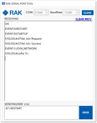 Figure 1: RAK7432/RAK7434 successful join
Connect to The Things Stack
This section shows how to register the RAK7432/RAK7434 with The Things Stack using OTAA.
Before starting, ensure that a LoRaWAN gateway using the required frequency plan is connected to The Things Stack and is within range of the RAK7432/RAK7434.
First, log in to TTNv3. To do so, head to the TTNv3 site. If you already have a TTN account, you can use your The Things ID credentials to log in.
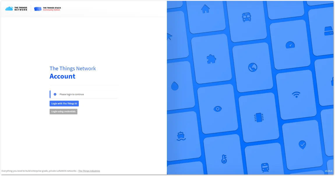 Figure 1: The Things Network home page
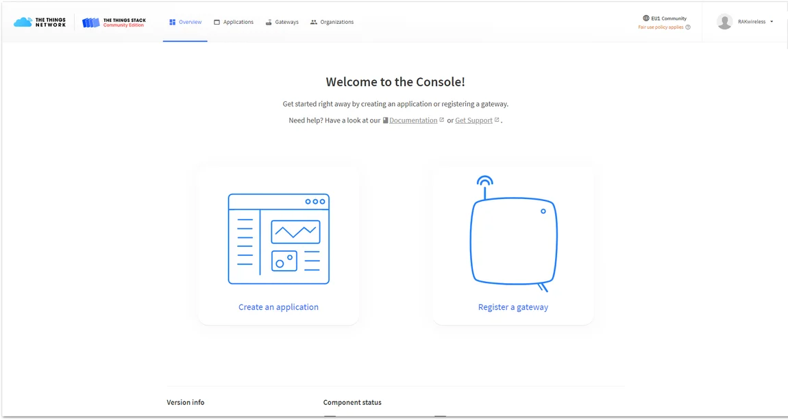 Figure 1: The console page after successful login
Create an Application
This tutorial is for the EU868 Frequency band.
- To create an application, choose Create an application (for new users that do not already have created applications) or Go to applications > + Add application (for users that have created applications before).
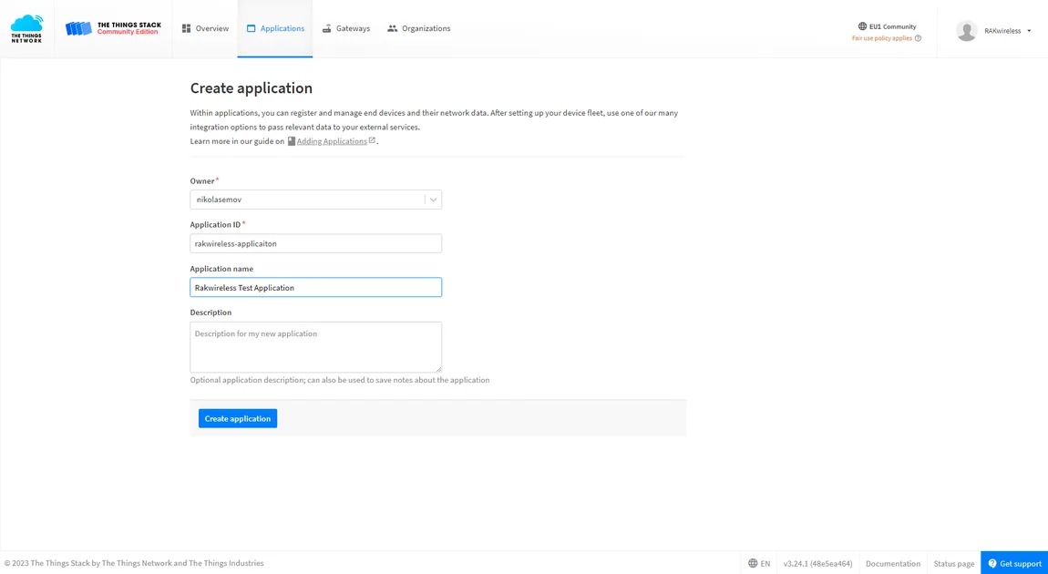 Figure 1: Create an application
- Fill in the needed information:
- Owner - Automatically filled by The Things Stack, based on your account or created Organization.
- Application ID - This will be the unique ID of your application in the Network. Note that the ID must contain only lowercase letters, numbers, and dashes (-).
- Application name (optional) - This is the name of your application.
- Description (optional) – Description of your application. Optional application description; can also be used to save notes about the application.
- After you fill in the information, click Create application. If everything is filled in correctly, you will see the same page, as shown in Figure 21.
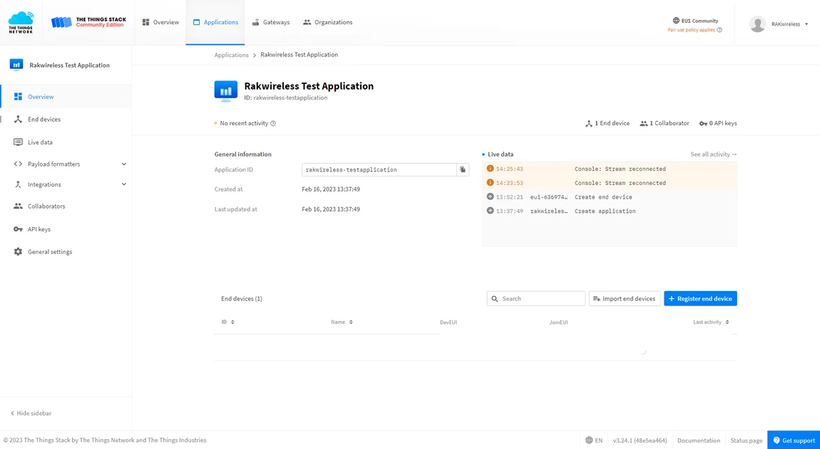 Figure 1: Application overview
Register and Configure the Device in OTAA Mode
Register the Device in OTAA Mode
- From the Application Overview page, click + Register end device.
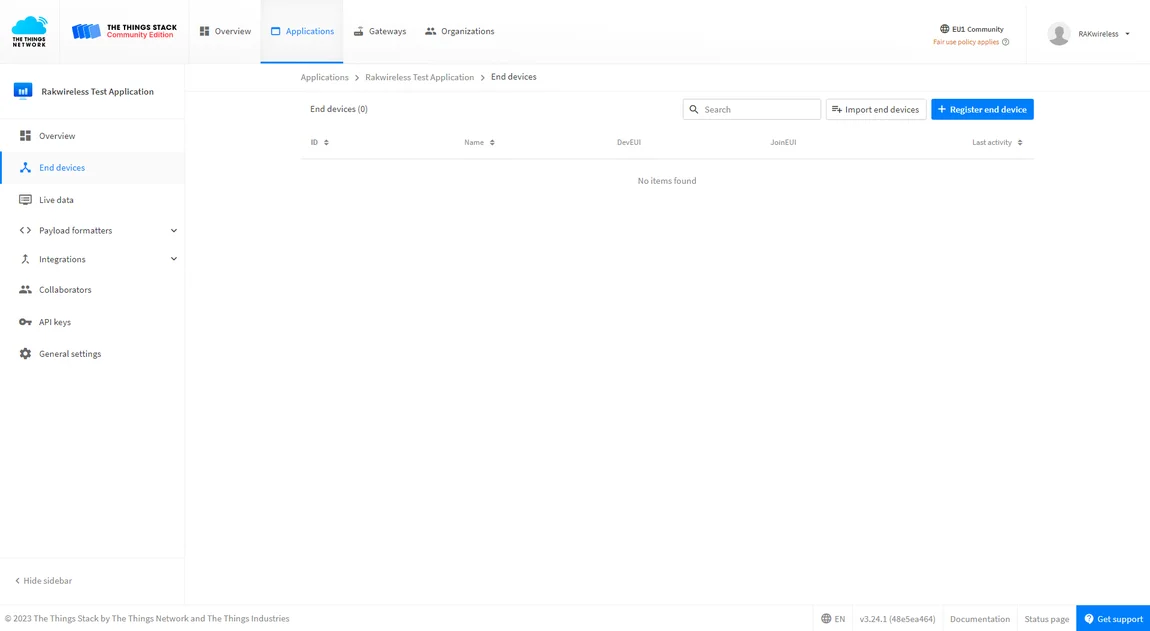 Figure 1: Adding a device in OTAA mode
 - Select Enter device specifics manually and fill in the Frequency plan.
- Select LoRaWAN version 1.0.3 and fill in the JoinEUI (AppEUI).
NOTE
For this example, the Europe 863-870 MHz (SF9 for RX2 - recommended) plan is chosen.
- For the JoinEUI, the AppEUI uniquely identifies the owner of the end device. It is provided by the device manufacturer. To get the AppEUI, connect your device via a USB cable to your computer. Open RAK Serial Port Tool, choose the correct COM port and BaudRate, and run the following command:
AT+APPEUI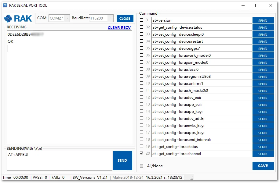 Figure 1: AppEUI of the device
 - Press the Confirm button next to the JoinEUI field.
`
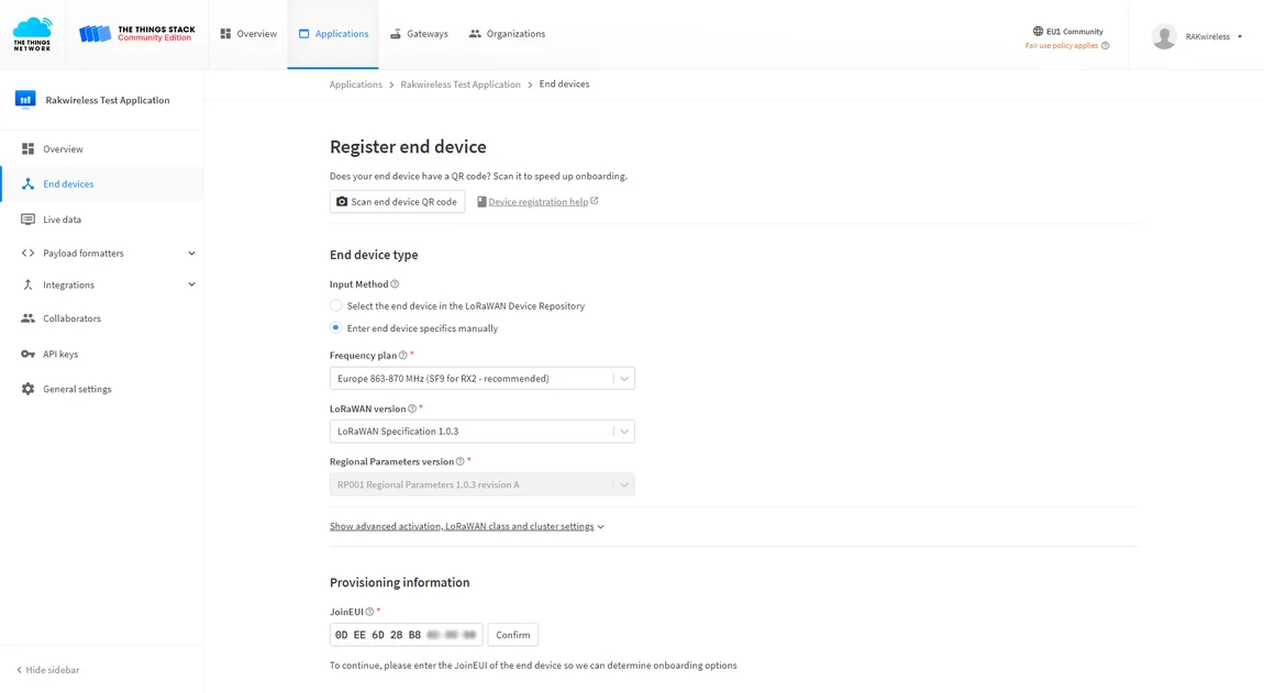 Figure 1: Registering the device
 - The Provisioning information section will expand. Scroll down to enter the required data for the device.
Here you must enter the following information:
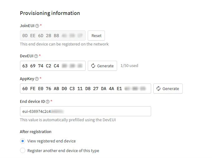 Figure 1: Registration Data
- DevEUI - The DevEUI is the unique identifier for this end device. It is provided by the manufacturer and is printed on the label on the back of the device.
- AppKey - The root key to deriving session keys to secure communication between the end device and the application. AppKey can be generated by clicking the Generate button
 .
. - End device ID – The End device ID is automatically filled based on the DevEUI. It can be changed. Note that the end device ID must contain only lowercase letters, numbers, and dashes (-).
NOTEIf you are going to register more than one device of this type, you can choose the option Register another end device of this type and be transferred to the same page to register the next device.
- After filling in the registration information, click Register end device.
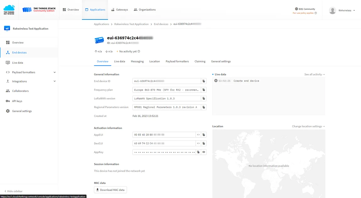 Figure 1: Registered device
Configure the Device in OTAA Mode
- For configuring the node you will need the following three parameters: Device EUI, Application EUI, and Application Key. You can see them all on the Device Overview page, but since the two EUIs come with the device, you only need the Application Key from there.
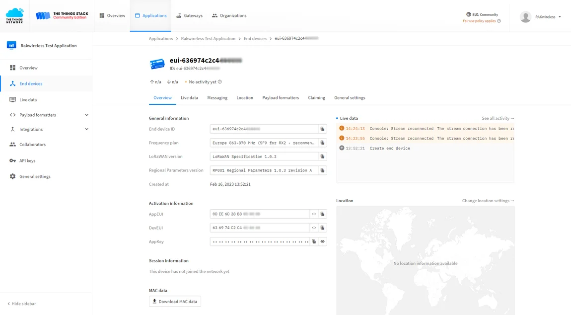 Figure 1: OTAA device parameters
 - Using the RAK Serial Port Tool, set the join mode, device class, and your LoRaWAN region to your correct frequency band, with the following set of AT commands:
-
For the join mode (OTAA)
AT+JOINMODE=OTAA -
For the class (Supported classes are: Class A, Class B, and Class C. Remember for different classes to change the command with the correct letter, for example for Class B it will be AT+CLASS=B, in this case, it is Class A.)
AT+CLASS=A -
For the region, replace the frequency band with the one of your LoRaWAN region. Refer to the TTN site to see more about your frequency plan.
AT+REGION=EU868
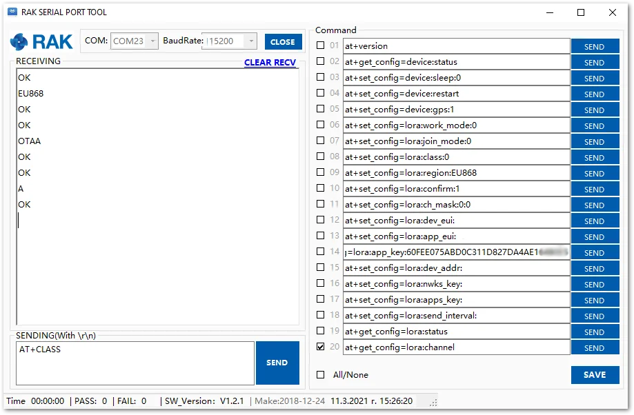 Figure 1: Setting up the RAK7432/RAK7434 operating modes
The following tutorial is based on using the EU868 frequency band.
- Now that those parameters are set, enter the App Key, using the command below. Remember to replace the "XXXX" with the corresponding parameter value for your particular case.
AT+APPKEY=XXXX
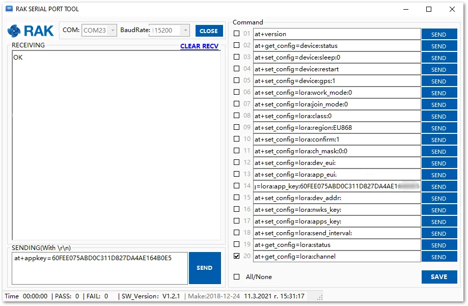 Figure 1: Setting up the RAK7432/RAK7434 OTAA parameters
- To connect to the LoRaWAN Network after configuration, the device must be restarted. Restart it with the command:
AT+RESTART
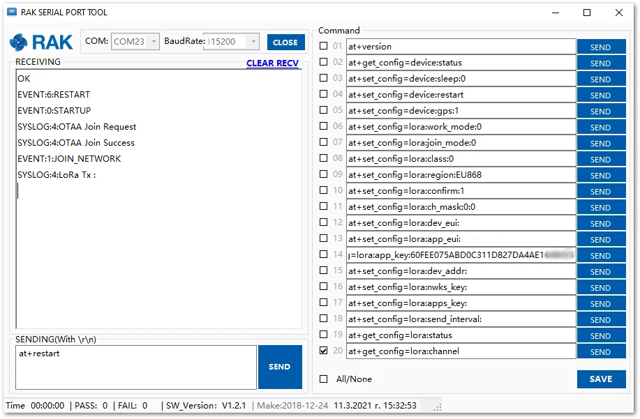 Figure 1: Joining the network configuration
- You can see in the Live data feed that the RAK7432/RAK7434 WisNode Bridge Analog is successfully joined.
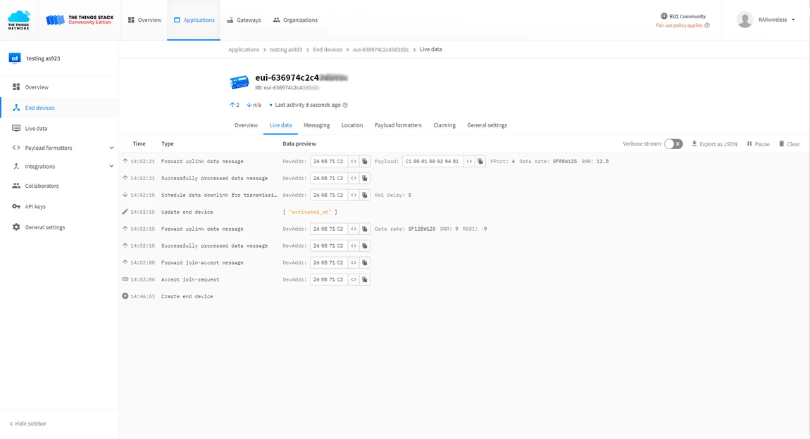 Figure 1: Receiving data in the Live data feed
Configure the Analog Interface
Modifying the following values is not necessary but depends on the use case you need.
- Let’s set the AINPERIOD. This value determines the acquisition reporting period. The default value is 600 s. Now we are going to set it to 100 s:
AT+AINPERIOD=100
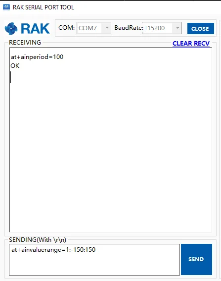 Figure 1: AINPERIOD command execution
- The next step is to change the value range (the minimum and maximum value) of the analog interface data.
AT+AINVALUERANGE=1:-150:150
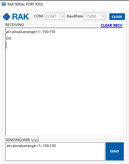 Figure 1: AINVALUERANGE command execution
- AINLPMODE (Low power mode) will also need to be changed. Enabling this value will allow the analog data input interface to be turned off while the device is in AINPERIOD (while no acquisition is initiated).
AT+AINLPMODE=1
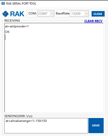 Figure 1: AINLPMODE command execution


