RAK5010-BG95 WisTrio NB-IoT Tracker Pro Quick Start Guide
Prerequisites
Before going through every step in the installation guide of the RAK5010-BG95 WisTrio NB-IoT Tracker Pro, make sure to prepare the necessary items listed below:
- RAK5010-BG95 WisTrio NB-IoT Tracker Pro
- USB-UART Module (RAKDAP1 Tool)
- Jumper Wires
- Micro USB / 3.7 V rechargeable battery / 5 V Solar Panel Port
- JTAG Emulator
This device released by RAKwireless is already pre-loaded with its latest firmware upon manufacturing. If you want to have your device firmware burned or upgraded, refer to the following sections:
Package Inclusions
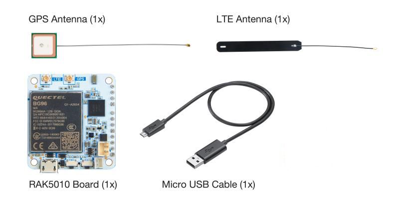 Figure 1: Included Items in RAK5010-BG95 Package
Product Configuration
Checking Device Logs
There are three ways that you can check the logs for debugging purposes on your RAK5010-BG95 WisTrio NB-IoT Tracker Pro:
- Through J-Link RTT Viewer
- Through UART
- Through Micro-USB
Through J-Link RTT Viewer
- If you want to check the logs of RAK5010-BG95 WisTrio NB-IoT Tracker Pro using this method, make sure you have connected the RAK5010-BG95 with your PC through JTAG as shown in Figures 2 and 3.
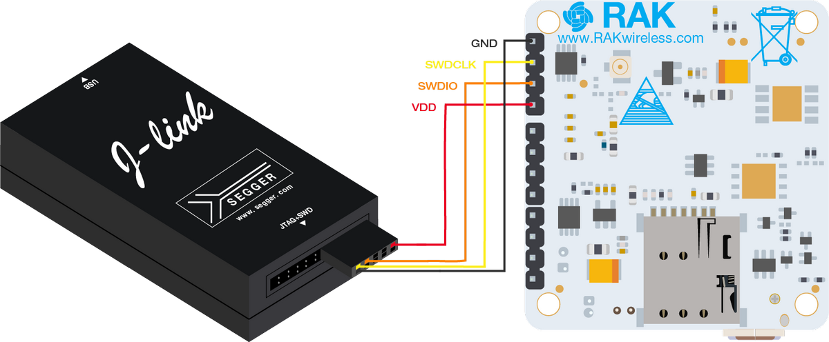 Figure 1: RAK5010-BG95 and PC Connection through JTAG
You still have to connect the Micro USB Cable to the RAK5010-BG95 to power the board.
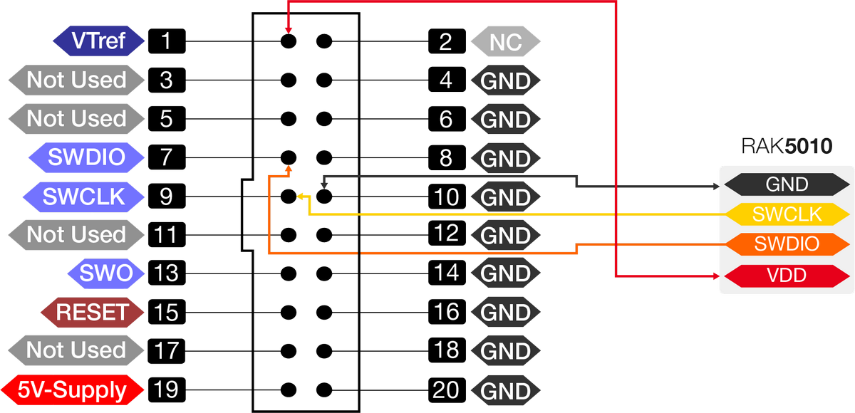 Figure 1: J-Link Connector to RAK5010
VDD of RAK5010-BG95 is rated only to 1.8 V. It must not be connected to 3.3 V or 5 V.
- Go to the official website of Segger where you can download the J-Flash software. Open the program J-Link RTT Viewer V6.60f and choose USB for the type of connection to J-Link. After which, press OK.
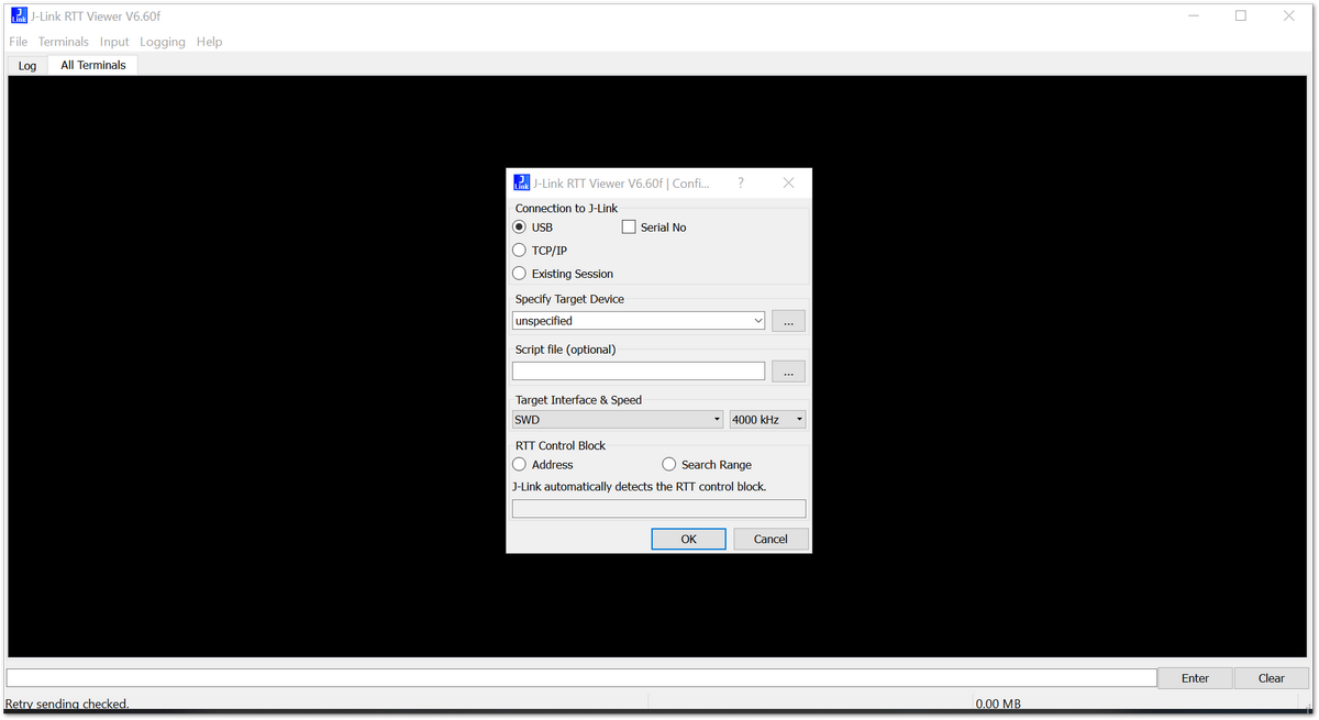 Figure 1: J-Link RTT Viewer
- Choose the device parameters as shown in Figure 5 or the table provided, then press OK.
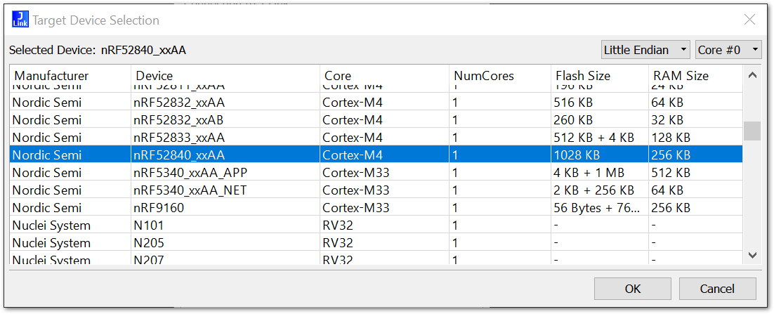 Figure 1: J-Link Target Device Settings
| Parameter | Data |
|---|---|
| Manufacturer | Nordic Semi |
| Device | nRF52840_xxAA |
| Core | Cortex-M4 |
| NumCores | 1 |
| Flash Size | 1028 kB |
| RAM Size | 256 kB |
- Connect to your RAK5010-BG95 by navigating through File>Connect in the Main Menu. Alternatively, you could just press F2 to do the same process.
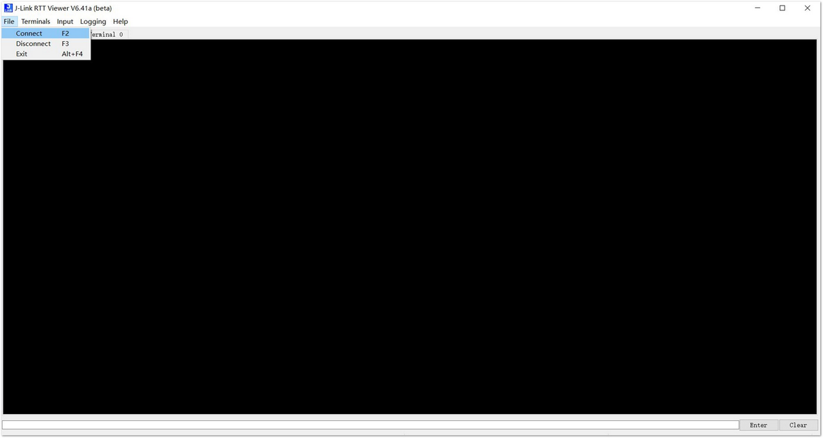 Figure 1: Connecting in J-Link RTT Viewer
- Once the connection is obtained, you should see the same log as shown in Figure 7.
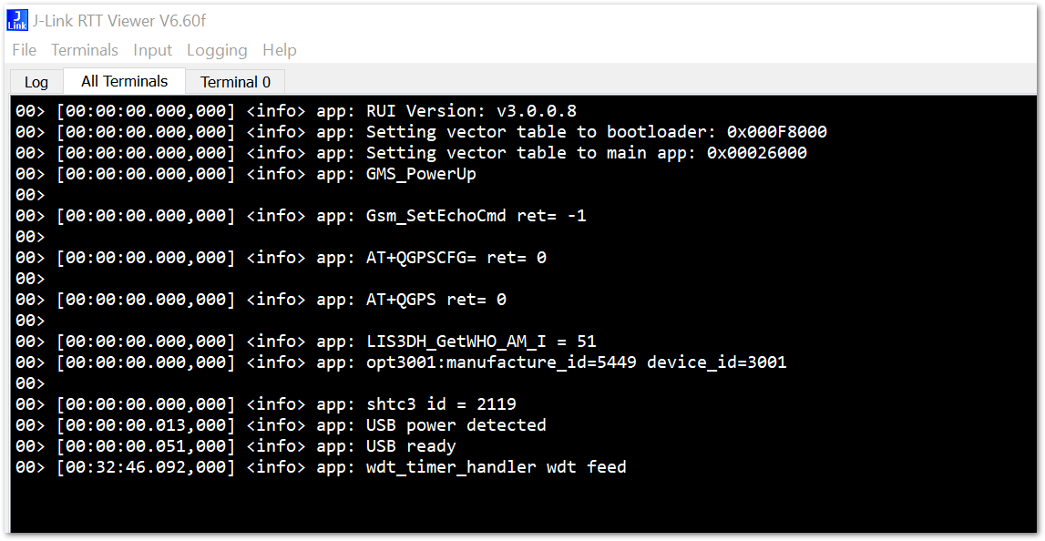 Figure 1: J-Link RTT Viewer showing RAK5010-BG95 Logs
If there is no log after connecting successfully, you can try to reset RAK5010. Ensure that the micro USB is connected properly or check the connection of the JTAG.
Through UART
- If you want to check the log of RAK5010-BG95 through UART, you should make sure that RAK5010-BG95 has been connected to your PC through the USB-UART module correctly as shown in Figure 8. It is highly recommended to use RAKDAP1 as the USB to UART interface. RAKDAP1 Tool is compatible with other RAK devices and can be used as a debugger and programmer as well.
 Figure 1: RAK5010-BG95 and USB-UART Connection
-
Open a serial port tool on your PC. If you don't have a serial port tool yet, download and install the RAK Serial Port Tool.
-
After pushing the RST button on RAK5010, you can see the following contents in the serial port tool as shown in Figure 9:
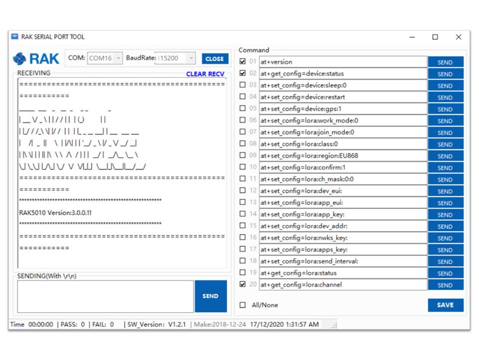 Figure 1: RAK Serial Port Tool
Through Micro USB
- To start with, connect RAK5010-BG95 with your PC through micro USB/USB as shown in Figure 10.
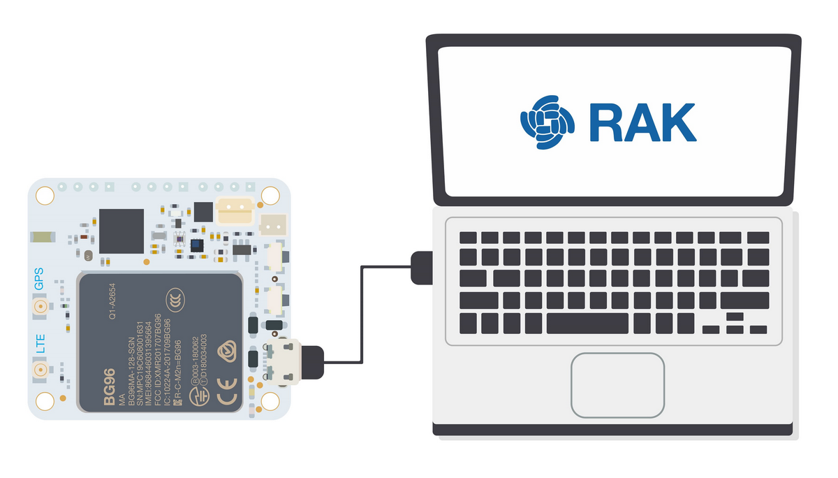 Figure 1: MicroUSB Interface for RAK5010
- Open the serial port tool on your PC.
- For this method, you need a serial port tool that can support the DTR function, like Termite. You can download Termite on their website.
- For Linux and MacOS, the alternative is Coolterm.
- It is highly recommended to connect a battery when doing configuration via USB to have a stable serial connection.
- After opening the Termite serial tool, configure its setting as shown in Figure 11.
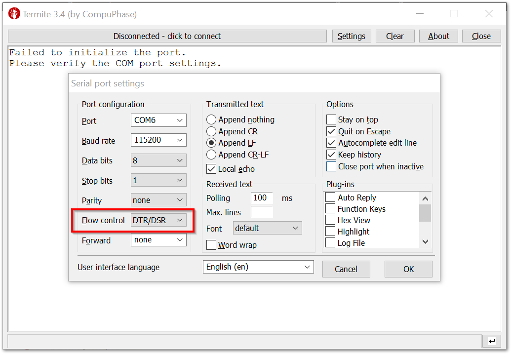 Figure 1: Termite Configuration Enabling DTR
- Now, the Termite app will connect with RAK5010-BG95 automatically. Then you can send AT commands and check the log in Termite.
 Figure 1: Checked Log in Termite
Configuring RAK5010
You can configure your RAK5010-BG95 WisTrio NB-IoT Tracker Pro by sending AT Commands either through UART, BLE, or Micro USB.
For the full list of AT Commands available for configuring your RAK5010, check the AT Command Manual.
Through UART
-
As mentioned in the Checking Device Logs section, if you want to use RAK5010-BG95 WisTrio NB-IoT Tracker Pro through UART, you should connect the RAK5010-BG95 in your PC through UART as shown in Figure 8.
-
Try to send a simple AT command to RAK5010-BG95 to get the current firmware version by sending the command below using the RAK Serial Port Tool. Similarly, you can send other AT commands of RAK5010-BG95 in the same way.
at+version
 Figure 1: AT command for Firmware Version
Through BLE
- To configure the RAK5010-BG95 WisTrio NB-IoT Tracker Pro through BLE, download and install nRF Connect developed by Nordic Semiconductor. The App is available both in App Store and Google Play Store.
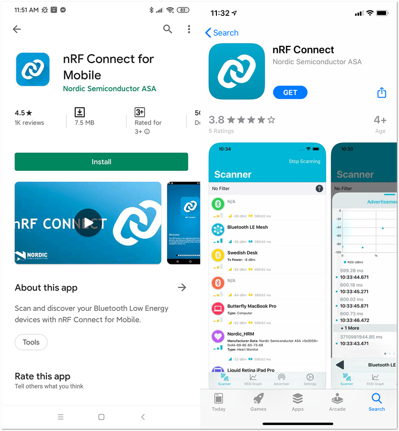 Figure 1: nRF Connect App in Android and IOS
- Make sure the Bluetooth on your mobile is turned on. Open the application and you will see all BLE devices in range in the scan list.
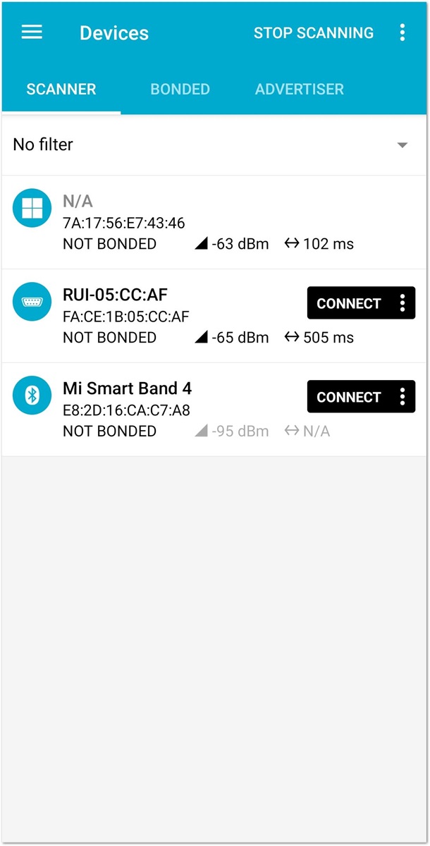 Figure 1: Available Bluetooth Devices in the Nordic App
- Press the reset button on the RAK5010-BG95 Board and wait for a couple of seconds. Look for a BLE Device named RUI-... in the scan list of the app. Connect to this device and click Nordic UART Service.
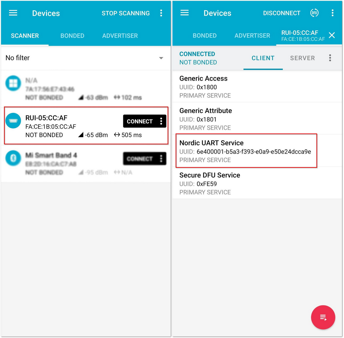 Figure 1: Nordic UART Service in the Nordic App
By default, the BLE signal of the RAK5010-BG95 is turned off automatically if no connection is established after 60 seconds. Connect to the BLE signal of the RAK5010-BG95 immediately after pressing the reset button.
- Click the arrow marked by the red box, as shown in Figure 17.
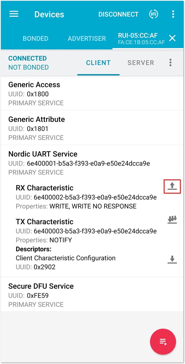 Figure 1: RX Characteristic in the Nordic UART Service
- You can now send AT commands to the RAK5010. Meanwhile, you can also see log information in RTT Viewer as discussed in Checking Device Logs.
- For example, if you want to check the current firmware version, send the following command:
at+version
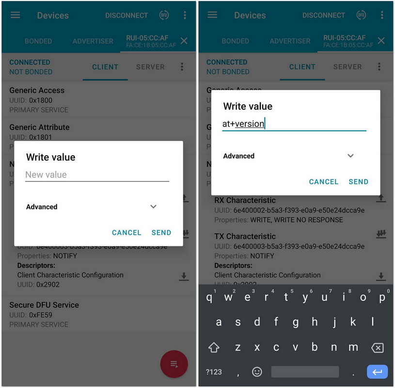 Figure 1: Sending AT Command via Nordic App
- Then, you can see the version number in the RTT Viewer tool.
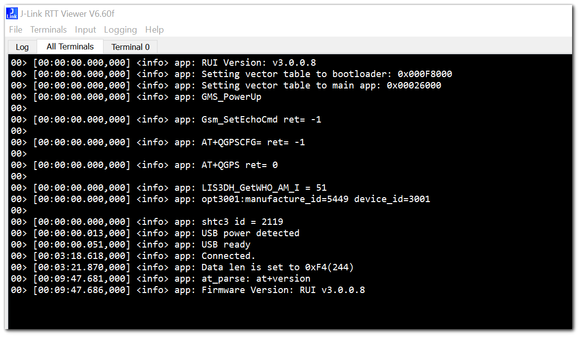 Figure 1: Log Info in J-Link RTT Viewer
Through Micro USB
Configuring the RAK5010-BG95 and checking logs via USB has the same setup. Refer to the guide on USB connection in the checking device logs section.
Connecting Cellular Network and Sending Packets over Cellular
In this section, you will learn more about how to connect to the Cellular Network of your device.
- To start with, insert a SIM card into your RAK5010. For this section, a China Mobile SIM card is used to have a GSM network connection.
As described in the previous section, there are three ways to configure our RAK5010: through UART, BLE, and micro USB. For this section, configuring the RAK5010-BG95 through UART is used as an example.
There are two ways to connect and send packets to Cellular Network: Manual and Automatic.
Manual Connection
- To begin with, send the following AT command to scan cellular networks:
at+scan=cellular
- Ensure that the LTE Antenna of the RAK5010-BG95 is connected properly.
- Alternative command to
at+scan=cellularisat+set_config=cellular:(AT+COPS=?). - Complete the details of the BG95-M3 TCP AT commands manual can be downloaded from the Quectel website.
 Figure 1: Scanning for Cellular Networks
- Wait for about 30 seconds, then you will see the following output in the serial port tool the same as shown in Figure 21:
 Figure 1: Scanned Cellular Network shown in Serial Port
- As you can see, the RAK5010-BG95 has scanned around the Cellular network and shown them in the serial port tool.
To configure the operator information, the following command is used:
at+set_config=cellular:(AT+COPS=1,0,"CHINA MOBILE",0)
- The last parameter of AT+COPS command is the type of connection: 0-GSM, 8-LTE CAT-M1, 9-LTE CAT-NB1.
- For example, if you want to connect to LTE CAT-M1, the command must be
at+set_config=cellular:(AT+COPS=1,0,"CHINA MOBILE",8). - You can also check if your configuration is saved correctly with this command:
at+set_config=cellular:(AT+COPS?). - Complete the details of the BG95-M3 TCP AT commands manual can be downloaded from the Quectel website.
 Figure 1: Configuring the Operator
Now, continue to configure the network:
at+set_config=cellular:(AT+QICSGP=1,1,"CMCC","","",1)
- The third parameter of AT+QICSGP command is the APN of the cellular network. This is different per country and dependent on what cellular telecommunications company you want to connect with.
- Complete the details of the BG95-M3 TCP AT commands manual can be downloaded from the Quectel website.
at+set_config=cellular:(AT+QIACT=1)
 Figure 1: Configuring the Cellular Network
 Figure 1: Configuring the Cellular Network
- Then, set the IP address of the server which will receive the packet sent from RAK5010.
at+set_config=cellular:118.31.121.60:12111:CHINA MOBILE:CMCC:CMNET:0
This IP address is just used for example. For your configuration, use your server IP address.
 Figure 1: Configuring the IP Address of the Server
- Next, try sending a packet manually over Cellular. Use the following command to send data over Cellular:
at+send=cellular:XXX
 Figure 1: Sending Data over Cellular
- As you can see, the data sent is 123456.
Now, check it on the receiving server:
 Figure 1: Received Data shown in the terminal
rak2016@iZbp1980wxsue6enel4qc0Z:/home/rak2001$ tail -f rak12111
[Tue Sep 24 18:37:36 2019] [new_client] accept client [117.132.196.229:14809], new_fd:6
[Tue Sep 24 18:37:46 2019] [handle_message]: client:6 recvbuf:123456
[Tue Sep 24 18:37:47 2019] [handle_message]: client:6 disconnect.
As you can see in Figure 27, the server has received the packet successfully, and the data sent is 123456, which is the same as the one you just sent out.
Automatic Connection
In this section, you will be connecting and sending data with cellular network, automatically.
- First, configure the parameters for the cellular operator information and the receiving server information as follows (a China Mobile SIM card based on a GSM network is used as an example):
at+set_config=cellular:118.31.121.60:12111:CHINA MOBILE:CMCC:CMNET:0
 Figure 1: Configuring the Cellular Network Parameters
- Then, set the interval for sending the loop as shown in Figure 29.
at+set_config=cellular:send_interval:1:180000
- During sleep (LEDs are all off), you cannot send any AT command to the RAK5010-BG95 module. You need to restart your device and before going to sleep, you must send the command
at+set_config=cellular:send_interval:0:180000to go back to normal mode.
 Figure 1: Setting the Loop Intervals
As you can see, the setting means that you open the sending loop and the interval time at 180 seconds. To know more details about the command, refer to the AT Command Manual.
- Now, restart RAK5010-BG95 by sending the following AT command:
at+set_config=device:restart
 Figure 1: Restarting your RAK5010
After restarting, the RAK5010-BG95 will automatically connect to the Cellular Network you set and send a looping packet of sensor data. Every time it sends a packet, RAK5010-BG95 will sleep for 180 seconds, which you just set, after which it will wake up and search for a GPS, build a new packet, and send it out.
- You will see a continuous loop as shown in Figure 31.
 Figure 1: Continuous Loop seen in The Serial Tool
- RAK5010-BG95 will send sensor data automatically in a loop. You can check the data in the receiving server:
Check the data in the receiving server:
rak2001@iZbp1980wxsue6enel4qc0Z:~$ tail -f rak121111
[Tue Sep 24 19:18:03 2019] [new_client] accept client [221.178.125.59:14996], new_fd:6
[Tue Sep 24 19:18:17 2019] [handle_message]: client:6 recvbuf:Acc:-732.00, -178.00,620.00; Tem:27.29;Hum:46.04; Pre:964.82; Lig:3.84; Lat(0-N,1-S):0,3411.777725,Lon(0-E,1-W):0,10852.877460; Battery:3.90;
As you can see, the server has received the packet which RAK5010-BG95 sends out successfully, and they are all sensor data in the packet.
Miscellaneous
Bluetooth Connection Modes
There are three BLE modes in RAK5010-BG95 from the firmware V3.0.0.6, the Peripheral Mode, the Central Mode, and the Beacon Scan Mode. You can change the work mode of RAK5010-BG95 BLE using the command provided in the AT Commands Manual.
at+set_config=ble:work_mode:X:Y
Description: Set the work mode for BLE.
- X - 0: BLE peripheral mode; 1: BLE central mode; 2: Beacon scan mode.
- Y - 0: Normal range; 1: BLE long range.
BLE Peripheral Mode
For the Peripheral Mode, you can scan RAK5010-BG95 BLE and connect with it using your mobile device.
BLE Central Mode
For the Central Mode, RAK5010-BG95 BLE will not broadcast, so that your mobile devices will not be able to scan it. This is very useful if you want to make the RAK5010-BG95 act as a BLE Gateway wherein BLE Sensor Nodes (up to 20 Devices) can send sensor data.
Beacon Scan Mode
For the Beacon Scan Mode, RAK5010-BG95 can scan around the Beacon signal. It is useful for Beacon use cases like iBeacon.
RAK5010 BLE Default Settings
By default, the RAK5010-BG95 will work on Peripheral Mode. In this mode, you can configure it through BLE, including DFU easily. It should be noted that after resetting the RAK5010, you only have 60 seconds to establish a connection with your mobile device through BLE based on its power consumption settings. If no connection has been established within 60 seconds, the RAK5010-BG95 BLE signal will not be broadcasted, and it will enter power-saving mode. On the other hand, there is no limitation once you are already connected with the RAK5010-BG95 BLE.
If you set the RAK5010-BG95 to work in Central Mode, it will first work in Peripheral Mode for 30 seconds, and if no connection is established after 30 seconds, it will automatically work in Central Mode. In this mode, the BLE signal of the RAK5010-BG95 will stop broadcasting and will not be visible on your mobile devices until you change the work mode to Peripheral Mode or reset the RAK5010-BG95.
Burning the Firmware
An easy and quick way to get started with your RAK5010-BG95 is by using pre-compiled firmware. However, if you want to compile your customized firmware, you can visit the RUI Customized Development documentation to learn how.
Installing J-Flash
- Go to the official website of Segger, and download the J-Flash software.
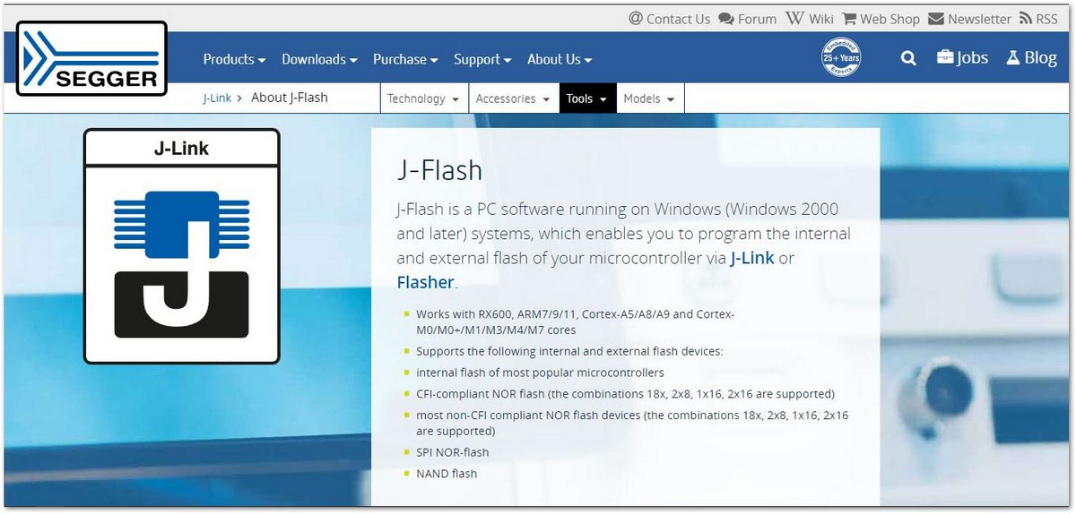 Figure 1: Segger Official Website
- Download the software that corresponds to your operating system. In this guide, Windows is used.
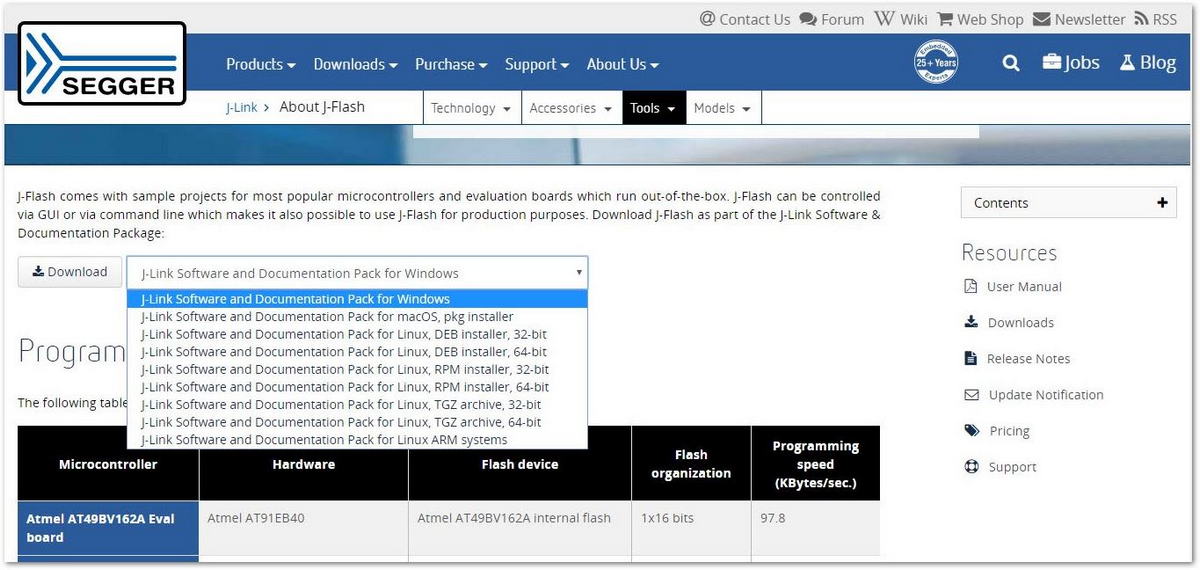 Figure 1: J-link Software in different platforms
- After you have downloaded your corresponding software, install it and wait for a couple of minutes.
Creating Project in J-Flash
- Upon opening the software, you will be greeted with a pop-up window. Choose Create a new project, then click Start J-Flash.
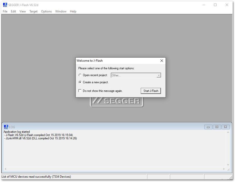 Figure 1: J-flash Interface
- You will be then prompted to configure your new project. Select the Target Device by clicking the box highlighted in red as shown in Figure 35.
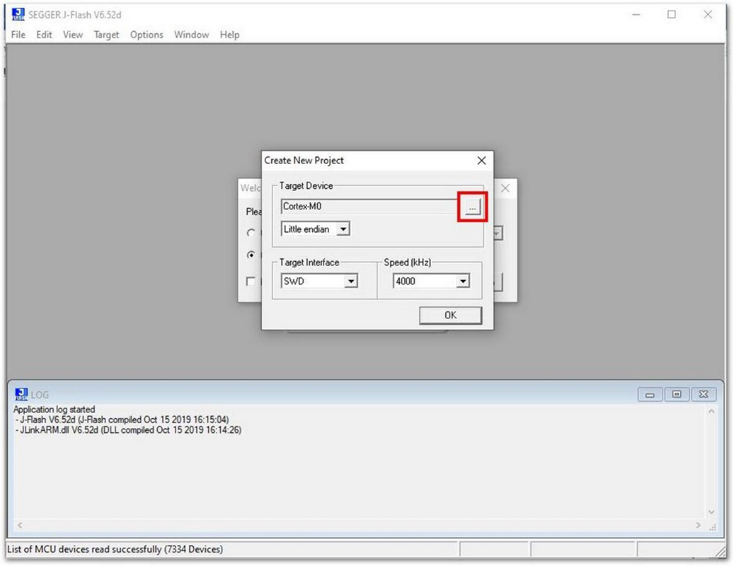 Figure 1: Configuring the Project
- Select the Manufacturer to Nordic Semi and Device nRF52840_xxAA.
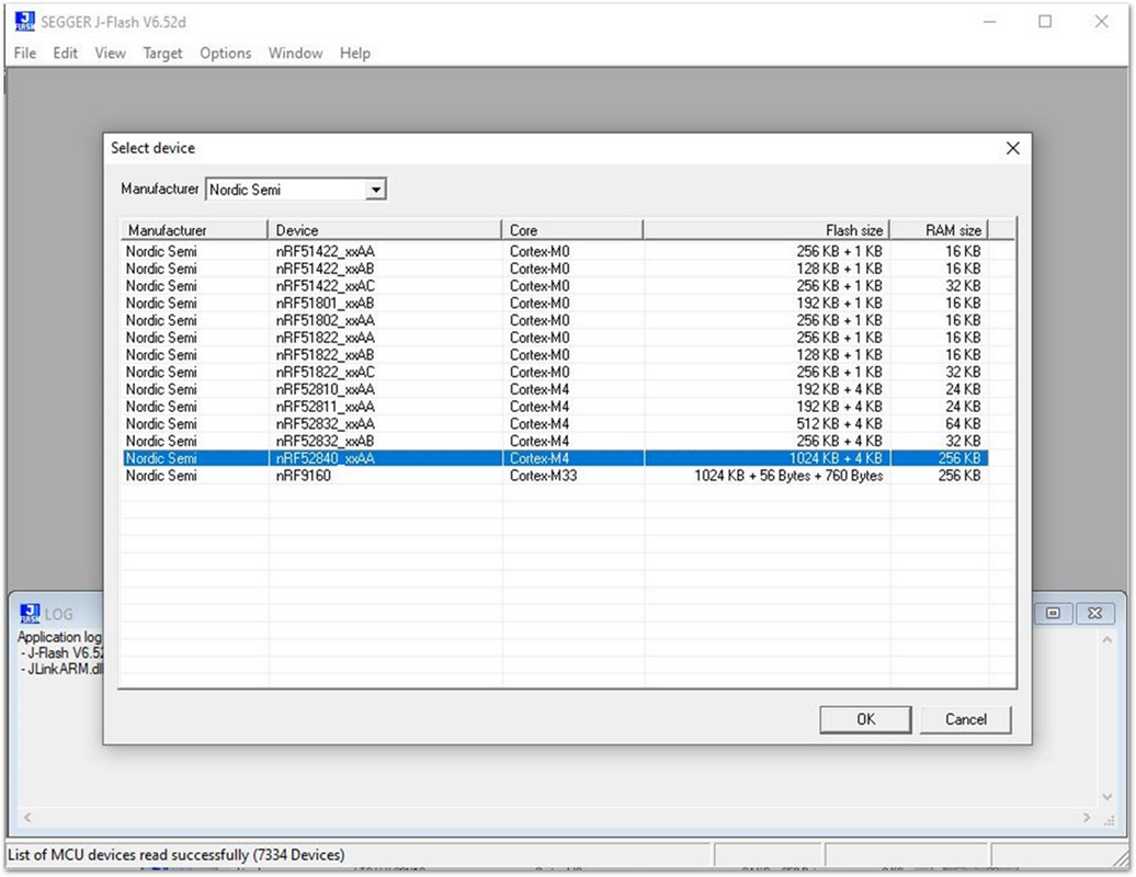 Figure 1: Selecting the Device
- Select the Target Interface to SWD and the Speed (kHz) to 4000. Press OK.
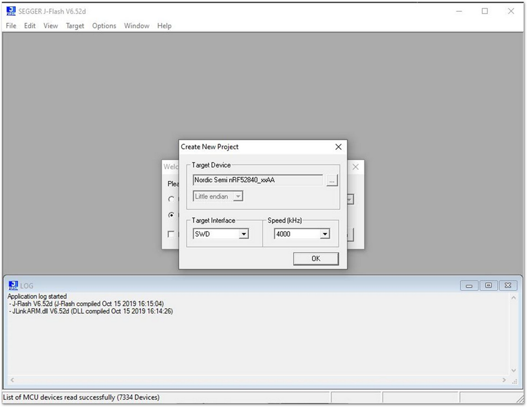 Figure 1: Target Interface and Speed (kHz)
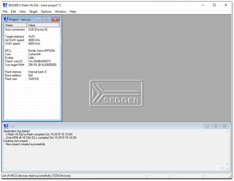 Figure 1: Created Project Successfully
Connecting the RAK5010 with JTAG
- Connect your RAK5010-BG95 to your PC through JTAG as shown in Figure 39. The pinout diagram and connection to Jlink can be found on the Datasheet.
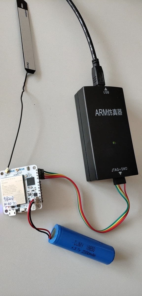 Figure 1: RAK5010-BG95 and JTAG Hardware Interface
-
Download the latest pre-compiled firmware from the RAKwireless Downloads and extract it to your PC.
-
In the J-Flash software Menu Bar, choose Target > Connect.
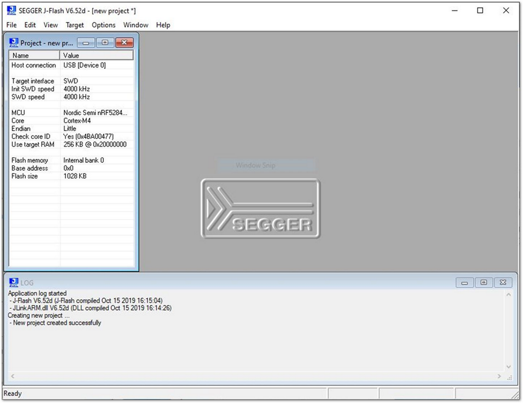 Figure 1: Successfully Created Project
- Now, choose the demo firmware that you have downloaded.
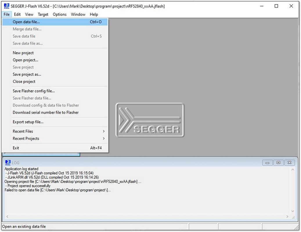 Figure 1: Selecting the Hex File
- Select Target -> Production Programming to start the flashing process, and wait for a couple of minutes.
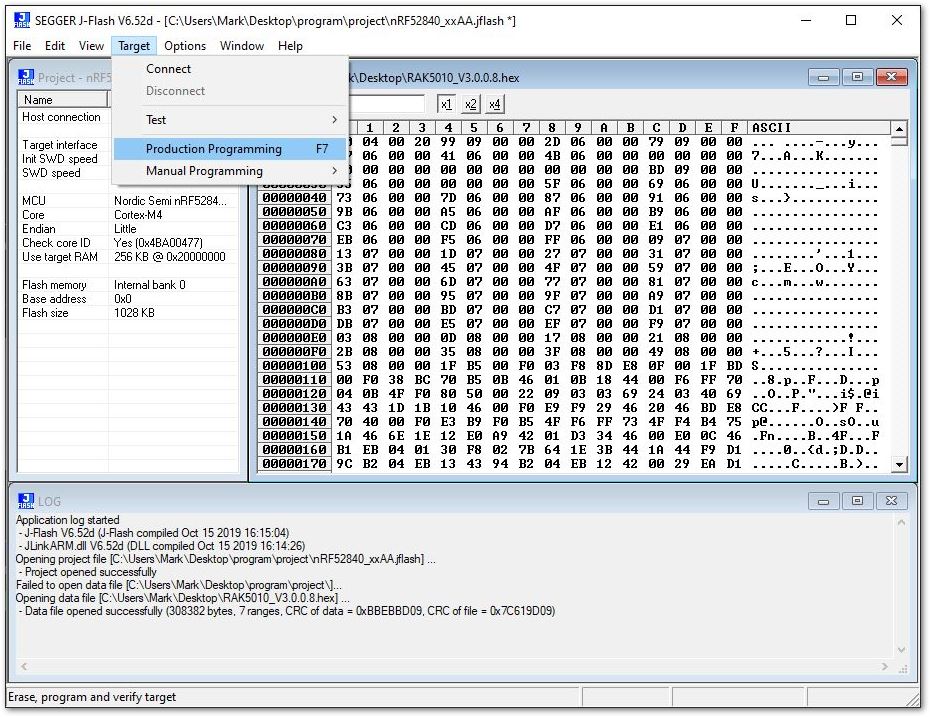 Figure 1: Connect with the RAK5010
Upgrading Firmware through DFU using BLE
-
Download the DFU package of the RAK5010-BG95 WisTrio NB-IoT Tracker Pro and save it on your mobile phone.
- DFU Package is inside the RAK5010_Latest_Firmware.zip with file name RAK5010_dfu_xxxxxxxxxxxx.zip
-
Make sure the Bluetooth on your mobile is turned on. Open the nRF Connect Mobile application, and you will see all BLE devices in range in the scan list.
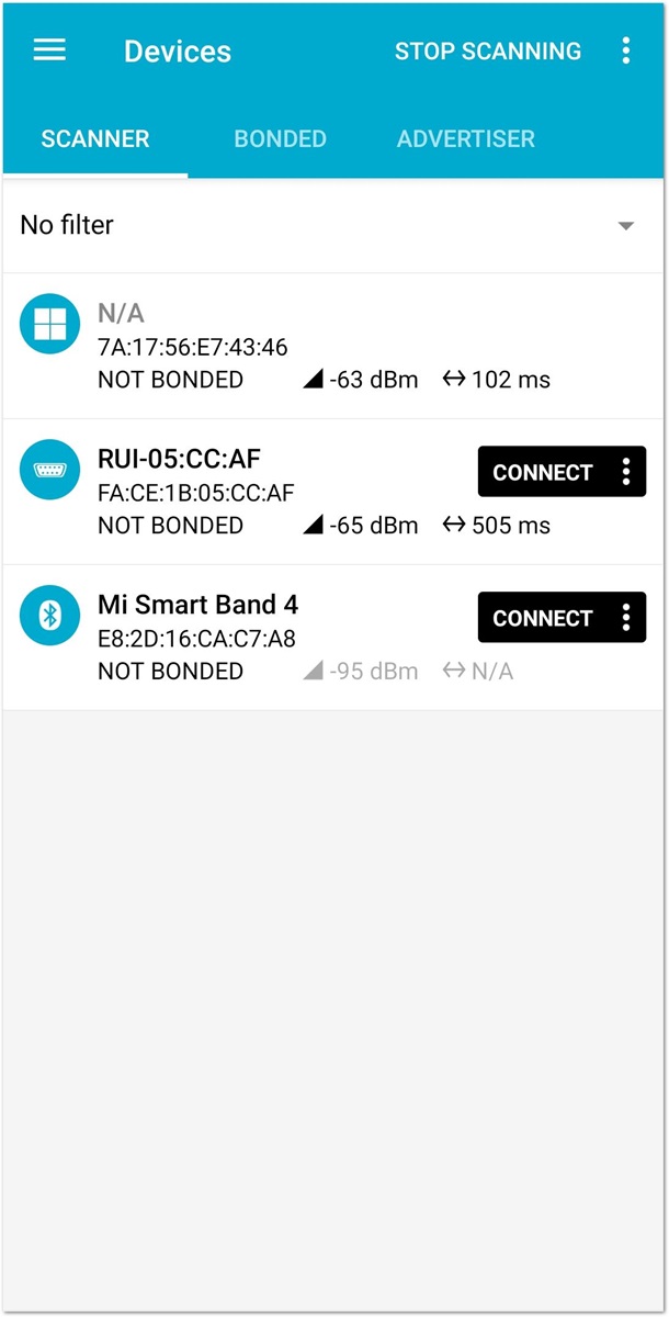 Figure 1: Available Bluetooth Devices in the Nordic App
- Press the reset button on the RAK5010-BG95 and wait for a couple of seconds. Look for a BLE Device named RUI-... in the scan list of the app. Connect to this device and click Nordic UART Service.
This will be only visible for 60 seconds. More information about the Bluetooth connection guide can be found in the Bluetooth Connection Modes section.
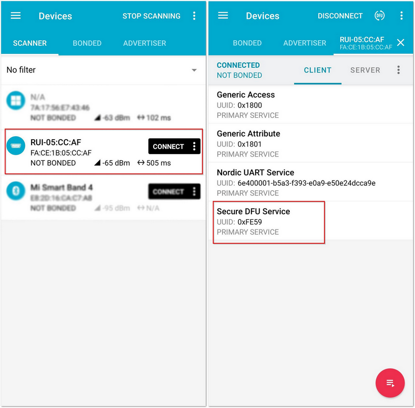 Figure 1: Secure DFU Service in the Nordic App
- Choose Secure DFU Service and click the button highlighted in red as shown in Figure 45.
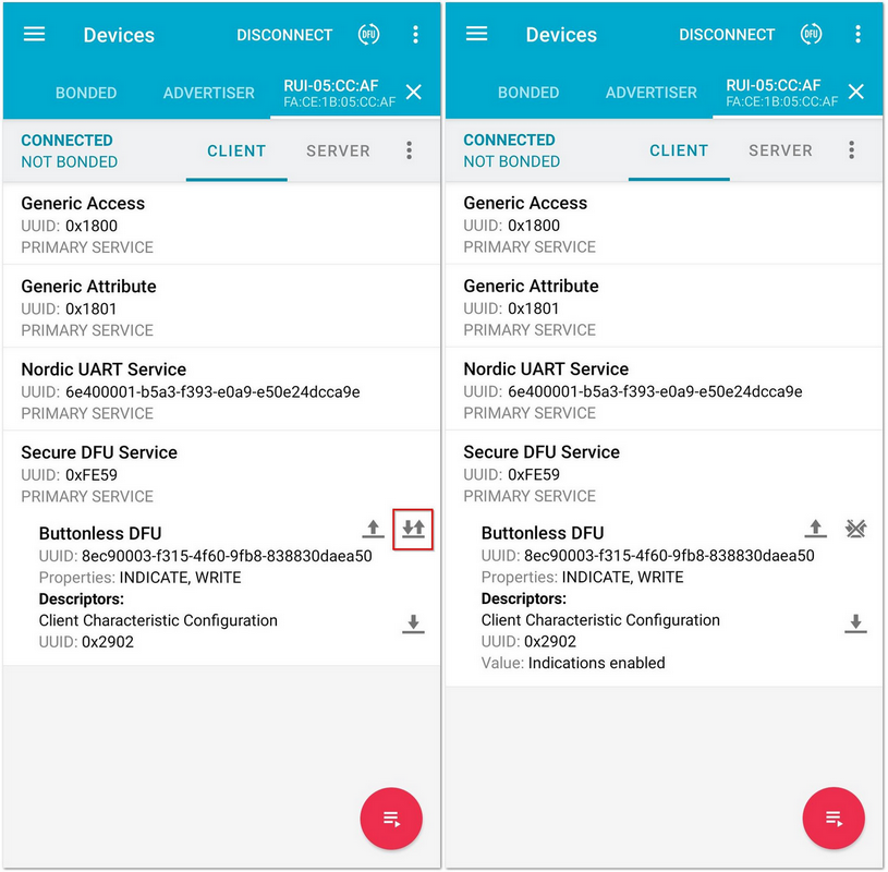 Figure 1: Buttonless DFU
- Click the arrow highlighted in red as shown in Figure 46. A Write Value window pop-up, then press Send.
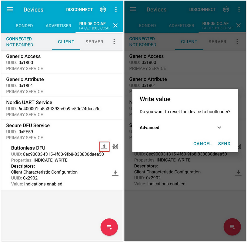 Figure 1: Resetting the Bootloader via Bluetooth
- Now, the RAK5010-BG95 is now working in DFU Mode. In the application, you will see the default status overview of RAK5010.
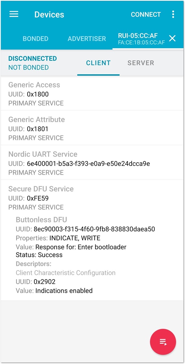 Figure 1: RAK5010-BG95 Default Status Overview after Resetting
- In the list of devices, find a BLE signal named DfuTarg and connect.
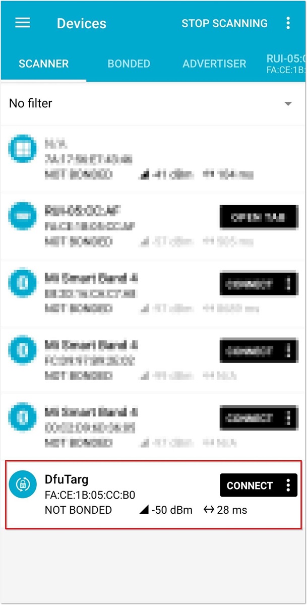 Figure 1: RAK5010-BG95 Default Bluetooth ID after Resetting
- After connecting, select the DFU Icon. Select the Distribution packet (ZIP) and press OK. This will then prompt you to select the zip file of the firmware that you have downloaded.
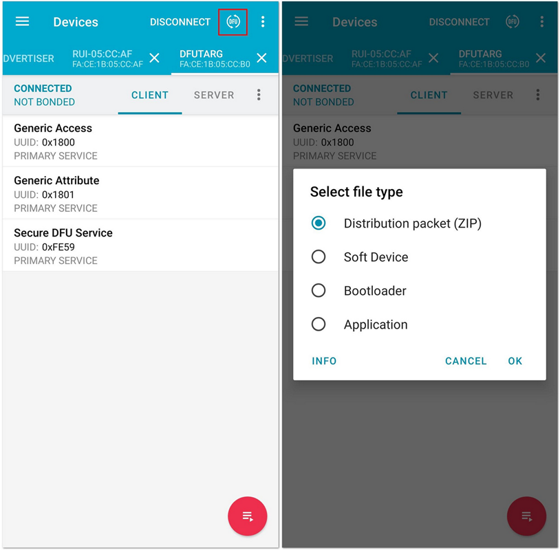 Figure 1: Distribution Packet File Type under DFU
- Then, it will automatically start to upgrade the firmware of your RAK5010-BG95 through DFU over BLE. After upgrading, it will restart and the DFU connection will be disconnected. Now, you can use your RAK5010-BG95 with the latest firmware.
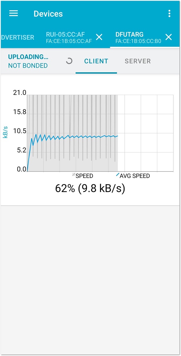 Figure 1: DFU Upgrading of RAK5010-BG95 Firmware via BLE